manuals.online logo
Brands
  1. Home
  2. •
  3. Brands
  4. •
  5. 3B SCIENTIFIC PHYSICS
  6. •
  7. Multimeter
  8. •
  9. 3B SCIENTIFIC PHYSICS 1018832 User manual

3B SCIENTIFIC PHYSICS 1018832 User manual

3B SCIENTIFIC®PHYSICS
1
Digital Multimeter E 1018832
Instruction sheet
12/19 SD/UD
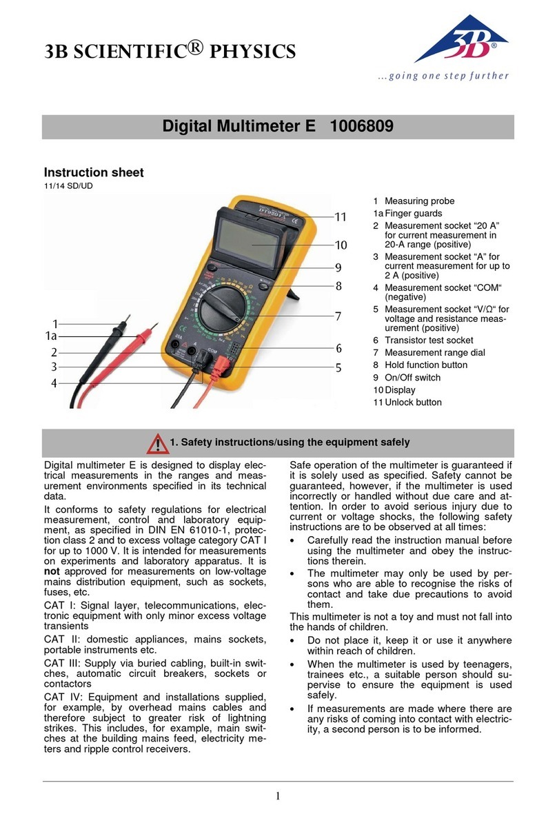
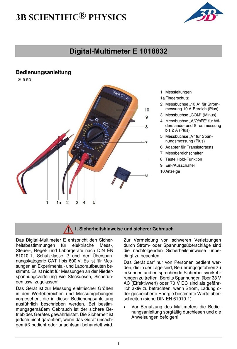
1 Measuring probe
1aFinger guards
2 Measurement socket “10 A”
for current measurement in
10-A range (positive)
3 Measurement socket “COM“
(negative)
4 Measurement socket “A/Ω/hFE”
for resistance and current meas-
urement for up to 2 A (positive)
5 Measurement socket “V“ for
voltage measurement (posi-
tive)
6 Adapter for transistor test
7 Measurement range dial
8 Hold function button
9 On/Off switch
10Display
1. Safety instructions/using the equipment safely
Digital multimeter E conforms to safety regula-
tions for electrical measurement, control and la-
boratory equipment, as specified in DIN EN
61010-1, protection class 2 and to excess voltage
category CAT I for up to 600 V. It is intended for
measurements on experiments and laboratory
apparatus. It is not approved for measurements
on low-voltage mains distribution equipment,
such as sockets, fuses, etc.
The meter is intended for measurements within
its measuring ranges and in a measuring environ-
ment as described in detail in the course of this
manual. Safe operation of the multimeter is guar-
anteed if it is solely used as specified. Safety can-
not be guaranteed, however, if the multimeter is
used incorrectly or handled without due care and
attention.
In order to avoid serious injury due to current or
voltage shocks, the following safety instructions
are to be observed at all times.
The multimeter may only be used by persons who
are able to recognise the risks of contact and take
due precautions to avoid them. Voltages in ex-
cess of 33 V AC (RMS) or 70 V DC are to be re-
garded as actively dangerous if the current,
charge or energy stored should exceed certain
values (see DIN EN 61010-1).
Carefully read the instruction manual before
using the multimeter and obey the instruc-
tions therein.
The multimeter may only be used in a dry,
dust-free environment with no risk of explo-
sions occurring.
2
The assumption needs to be made that unfore-
seen voltages may be present in the vincinity of
objects being measured (e.g. faulty equipment).
Before using the multimeter, check the hous-
ing and measuring leads for damage and if
there should be any malfunctions or visible
damage, the multimeter is not to be used.
Pay specific attention to the insulation for the
measuring sockets.
The multimeter may not be used to make
measurement on circuits which exhibit co-
rona discharge (high voltage).
Particular care is to be taken when making
measurements on high-frequency circuits
where dangerous voltages may arise due to
superimposition of components.
The authorised measuring range is not to be
exceeded. If measurements are made when
the magnitude of the variable is unknown, al-
ways select a large measuring range before
shifting down to lower ones.
Make very sure that the voltage value be-
tween the measured contact and earth or be-
tween the ground socket and the measure-
ment socket does not exceed 600 V.
Before using the multimeter to check that a
voltage source is not exhibiting any actual
voltage, check that the meter is working
properly by selecting the battery test function.
When measuring current, make sure the
electricity is turned off before the multimeter
is connected into the circuit.
When making measurements, always con-
nect the ground lead first. Disconnect the sig-
nal measurement lead before unplugging the
ground.
Turn off the multimeter before opening the
casing, disconnect the power to the circuit
and the measuring leads from the multimeter.
If measurements are made where there are
any risks of coming into contact with electric-
ity, a second person is to be informed.
The multimeter should not be stored, set up
or operated within reach of children.
When the multimeter is used by teenagers,
trainees etc., a suitable person should super-
vise to ensure the equipment is used safely.
If measurements are to be made where volt-
ages exceed 33 V AC (RMS) or 70 V DC, be
especially careful and only use safety experi-
ment leads.
When using the measuring leads always hold
them with your fingers behind the finger
guard.
To avoid false readings, which may result in
electric shocks or injuries, always replace the
battery as soon as the flat battery indicator
( ) is displayed.
Never use the multimeter when its casing is
open.
Measuring categories according to DIN EN
61010-1.
CAT I or unstipulated: Approved for measure-
ments in circuits which are not directly con-
nected to the low voltage mains grid (e.g. bat-
teries).
CAT II: Approved for measurements in cir-
cuits which are directly connected, by a
mains lead and plug for instance, to the low
voltage mains grid (e.g. household or office
appliance and lab equipment).
CAT III: Approved for measurements in cir-
cuits which are part of a building’s wiring in-
stallation (e.g. stationary consumers, distri-
bution terminals, appliances connected di-
rectly to the distribution box).
CAT IV: Approved for measurements in cir-
cuits which are directly connected to the
source of the low voltage mains (e.g. electric-
ity meters, main service feed, primary excess
voltage protection).
2. Equipment supplied
1 Digital multimeter
1 Pair of measuring probes
1 Adapter for transistor test
1 Battery
1 Instruction manual
3. Symbol legend
Hazard, read instruction sheet
Dangerous voltages
VDC voltage
ADC current
VAC voltage
AAC current
Diode and continuity test
hFE Current amplifying factor of a transistor
+ -
3
ΩResistance
Flat battery
CAT Measuring categoryas per IEC EN 61010-
1
Double insulated casing
CE EU conformitymark
Earth symbol
4. Technical data
Dimensions: 90x190x35 mm approx.
Weight: 310 g approx. (with bat-
tery)
Display: 3½-digit LCD,
24 mm, max. 1999
Operating voltage: 9-V battery, 6F22
Fuse: F 2 A / 600 V
F10 A / 600 V
Connectors: 4-mm safety sockets
Measurements/second: 2 –3 times
Overload display: “1” shown on display
Overload protection:
Voltage limits: 1000 V DC or 750 V AC
long-term in all voltage
ranges
Current limits:
2 A range: max. 2 A
10 A range: max. 10 A for 10 s with
minimum interval 15
mins
Operating temperature: 0°C –40°C with
0 –75% humidity
Storage temperature: -10°C –50°C with
0 –75% humidity
Electrical safety:
Safety specifications: EN 61010-1
Excess voltage
category: CAT I: 600 V
Contamination level: 2
Protection type: IP20
Electromagnetic compatibility:
Interference emission: EN 55011:2009
Interference resistance:EN 61326-1:2013
V DC
Measuring
range
Resolu-
tion
Accuracy
2 V
1 mV
±(0.8% + 5 di-
gits)
20 V
10 mV
200 V
100 mV
600 V
1 V
±(1.0% + 5 di-
gits)
Input impedance: 10 MΩ
V AC
Measuring
range
Resolu-
tion
Accuracy
2 V
1 mV
±(1.0% + 5 di-
gits)
20 V
10 mV
200 V
100 mV
600 V
1 V
±(1.2% + 5 di-
gits)
Input impedance: 10 MΩ
Frequency range: 40 –400 Hz
A DC
Measuring
range
Resolu-
tion
Accuracy
20 µA
10 nA
±(1.8% + 2 digits)
200 µA
100 nA
2 mA
1 µA
20 mA
10 µA
200 mA
100 µA
±(2.0% + 2 digits)
2 A
1 mA
±(2.0% + 10 di-
gits)
10 A
10 mA
Measuring voltage drop: 200 mV
A AC
Measuring
range
Resolu-
tion
Accuracy
20 µA
10 nA
±(2.0% + 5 digits)
200 µA
100 nA
±(2.0% + 3 digits)
2 mA
1 µA
20 mA
10 µA
200 mA
100 µA
±(2.0% + 5 digits)
2 A
1 mA
±(2.0% + 10 di-
gits)
10 A
10 mA
Measuring voltage drop: 200 mV
Frequency range: 40 –400 Hz
+ -
4
Ω
Measuring
range
Resolu-
tion
Accuracy
200 Ω
0,1 Ω
±(1.0% + 10 di-
gits)
2 kΩ
1 Ω
±(1.0% + 4 digits)
20 kΩ
10 Ω
200 kΩ
100 Ω
2 MΩ
1 kΩ
20 MΩ
10 kΩ
±(1.0% + 10 di-
gits)
200 MΩ
100 kΩ
±(5.0% + 10 di-
gits)
Accuracy is given for 1 year after calibration at
23°C ±5°C, RH<75%.
5. Description
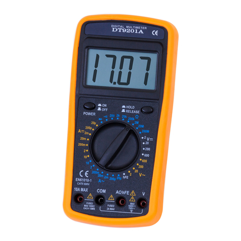
Digital multimeter E is a robust, battery operated
multimeter with a 3½-digit LCD display for meas-
uring voltage, current and resistance as well as
for diode and hFE gain testing.
All measurement ranges are selected by means
of a rotary dial. All measurement ranges are pro-
tected against overload.
The meter is equipped with a hold function, neg-
ative polarityindication, over range indication and
low battery indication.
On the backside there is a fold out prop for stand-
ing the device on a table.
6. Operation
Note: The multimeter switches into an indetermi-
nate state if the Hold button is activated (Hold
function button (8) pressed). After it is switched
on, the display will then show “1.666” (where the
position of the decimal point is dependent on the
selected measuring range). If this case should
arise, deactivate the Hold function while the
equipment is switched on (deactivate Hold func-
tion by pressing the button one more time).
6.1 Method of measurement
Warning! Dangerous voltages may
be present at the input terminals
and may not be displayed.
6.1.1 Voltage measurement
Set the measurement range dial at the re-
quired position or .
Connect the black test lead to the measure-
ment socket "COM" and the red test lead to
the "V" socket. The meter is connected paral-
lel to the measuring point. The polarity of the
red lead connection will be indicated at the
same time as the voltage when making a DC
measurement.
Note
lf the voltage to be tested is unknown before-
hand, set the measurement range dial to the
highest range and work down.
When only the figure "1" is displayed, over
range is being indicated and the measure-
ment range dial has be set to a higher range.
Never measure voltages higher than 600 V.
6.1.2 Current measurement
Set the measurement range dial at the re-
quired position or .
Connect the black test lead to the measure-
ment socket "COM" and the red test lead to
the " A/Ω/hFE" socket for measurements up
to 2 A. For measurements over 2 A connect it
to the socket “10 A”. The meter is connected
in series to the measuring object. The polarity
of the red lead connection will be indicated at
the same time as the current when making a
DC measurement.
Note
lf the current to be tested is unknown before-
hand, set the measurement range dial to the
highest range and work down.
When only the figure "1" is displayed, over
range is being indicated and the measure-
ment range dial has be set to a higher range.
Limit measurements in the 10-A range to
max. 10 s.
5
6.1.3 Resistance measurement
Warning! To avoid electrical shock
or damage to the meter when
measuring resistance in a circuit,
make sure the power to the circuit
is turned off and all capacitors are
discharged.
Set the measurement range dial to the Ω
range.
Connect the black test lead to the measure-
ment socket "COM" and the red test lead to
the " A/Ω/hFE" socket. Measurement is done
parallel to the resistor
Note
lf the resistance to be tested is unknown be-
forehand, set the measurement range dial to
the highest range and work dowWhen only
the figure "1" is displayed, over range is being
indicated and the measurement range dial
has be set to a higher range.
When the input is not connected, i.e. at open cir-
cuit, the figure "1" will be displayed for the over
range condition.
6.1.4 Diode test
Set the measurement range dial to .
Connect the black test lead to the measure-
ment socket "COM" and to the cathode of the
diode. Connect the red test lead to the "
A/Ω/hFE" socket and the anode of the diode.
Note: The meter displays the forward voltage
drop and displays figure "1" for overload when the
diode is reversed.
6.1.5 Continuity test
Warning! To avoid electrical shock
or damage to the meter when
measuring continuity in a circuit,
make sure the power to the circuit
is turned off and all capacitors are
discharged.
Set the measurement range dial to .
Connect the black test lead to the measure-
ment socket "COM" and the red test lead to
the " A/Ω/hFE" socket.
A built-In buzzer sounds if the resistance is less
than 30 ± 10 Ω.6.1.6 Transistor hFE test
Set the measurement range dial to hFE.
Insert the adapter for transistor test into the
the measurement sockets "COM" and "
A/Ω/hFE".
Make sure the transistor is "NPN" or "PNP"
type. Insert the transistor correctly into the
corresponding transistor test socket.
Display reading is approx. transistor hFE value
(0 –1000). Base current approx. 10 µA, VCE ap-
prox.2.8 V.
7. Maintenance
Turn off the meter and remove the test
leads before you service or clean the
device.
Beyond replacing batteries and fuses, do not at-
tempt to repair or service your meter unless you
are qualified to do so and have the relevant cali-
bration, performance test, and service instruc-
tions.
7.1 Battery and fuse replacement
Replace the battery as soon as the flat
battery icon ( ) appears.
Remove from the multimeter any bat-
teries which are flat or starting to disin-
tegrate.
Also remove batteries from the multi-
meter if it has not been used for a long
period of time.
Turn off the meter and remove the test
leads before opening the case.
Loosen screws with suitable screwdriver and
remove case bottom.
Replace the battery or the fuse.
Replace the case bottom and reinstall the
three screws. Never operate the meter unless
the case bottom is fully closed.
Do not dispose of the
battery in regular
household refuse.
Follow the local regu-
lations (In Germany:
BattG; EU:
2006/66/EG).
+ -
3B Scientific GmbH ▪ Ludwig-Erhard-Str. 20 ▪ 20459 Hamburg ▪ Germany ▪ www.3bscientific.com
Subject to technical amendments
© Copyright 2022 3B Scientific GmbH
Cleaning
Periodically wipe the case with a damp cloth
and mild detergent.
Do not use abrasives or solvents.
Dirt or moisture in the measurement sockets can
affect readings.
Shake out any dirt that may be in the meas-
urement sockets.
Soak a new swab with isopropyl alcohol and
work around the inside of each measurement
socket.
8. Disposal
The packaging should be disposed of at local
recycling points.
Should you need to
dispose of the equip-
ment itself, never
throw it away in nor-
mal domestic waste.
Local regulations for
the disposal of elec-
trical equipment will
apply.
Do not dispose of the battery in regular
household refuse. Follow the local regula-
tions (In Germany: BattG; EU: 2006/66/EG).

Other 3B SCIENTIFIC PHYSICS Multimeter manuals

3B SCIENTIFIC PHYSICS E 1018832 User manual

3B SCIENTIFIC PHYSICS

3B SCIENTIFIC PHYSICS E 1018832 User manual

3B SCIENTIFIC PHYSICS U17451 User manual

3B SCIENTIFIC PHYSICS

3B SCIENTIFIC PHYSICS U17451 User manual

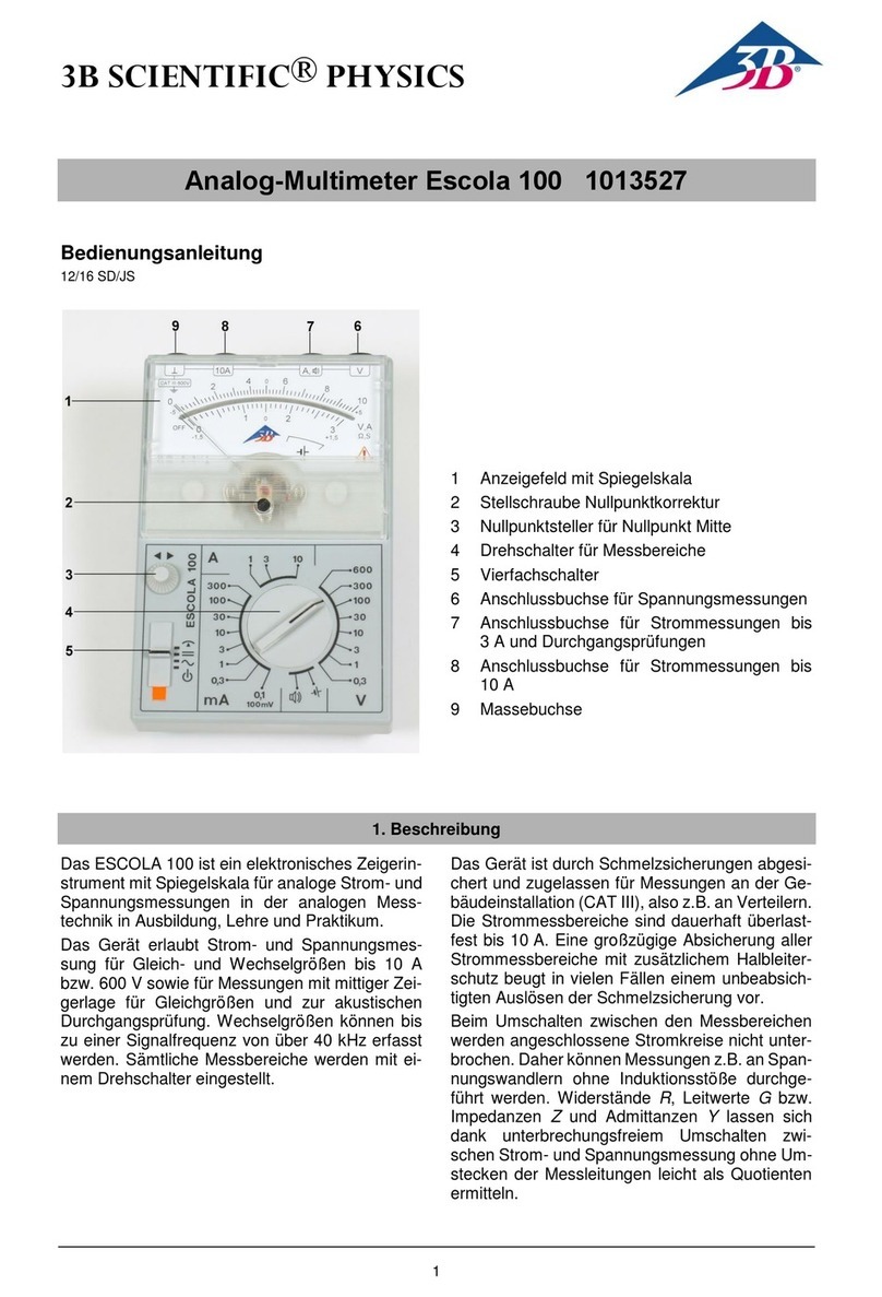
3B SCIENTIFIC PHYSICS 100 User manual

3B SCIENTIFIC PHYSICS

3B SCIENTIFIC PHYSICS 100 User manual

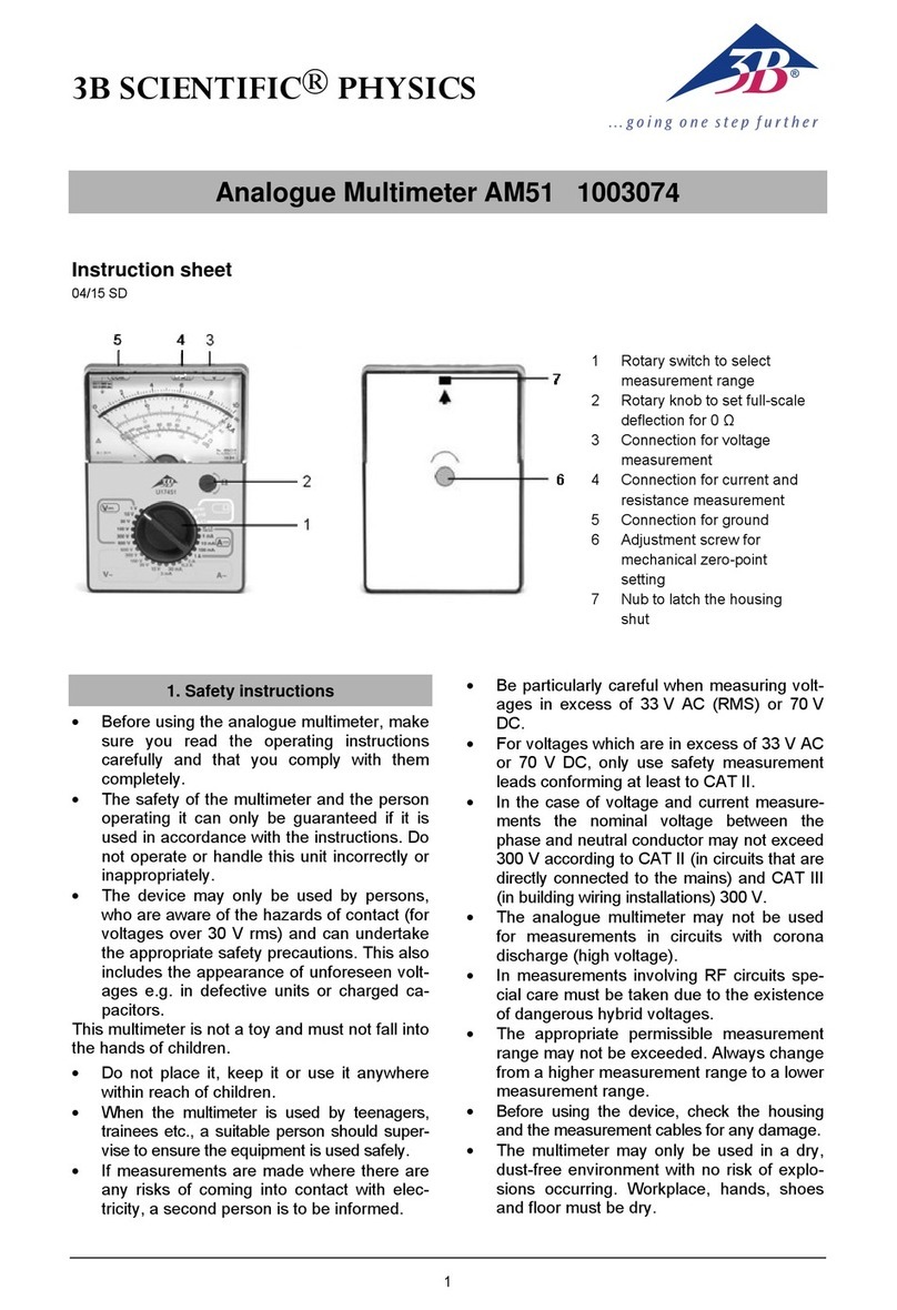
3B SCIENTIFIC PHYSICS AM51 User manual

3B SCIENTIFIC PHYSICS

3B SCIENTIFIC PHYSICS AM51 User manual

3B SCIENTIFIC PHYSICS DT9201A User manual

3B SCIENTIFIC PHYSICS

3B SCIENTIFIC PHYSICS DT9201A User manual

3B SCIENTIFIC PHYSICS E 1018832 User manual

3B SCIENTIFIC PHYSICS

3B SCIENTIFIC PHYSICS E 1018832 User manual

3B SCIENTIFIC PHYSICS Escola 2 User manual

3B SCIENTIFIC PHYSICS

3B SCIENTIFIC PHYSICS Escola 2 User manual

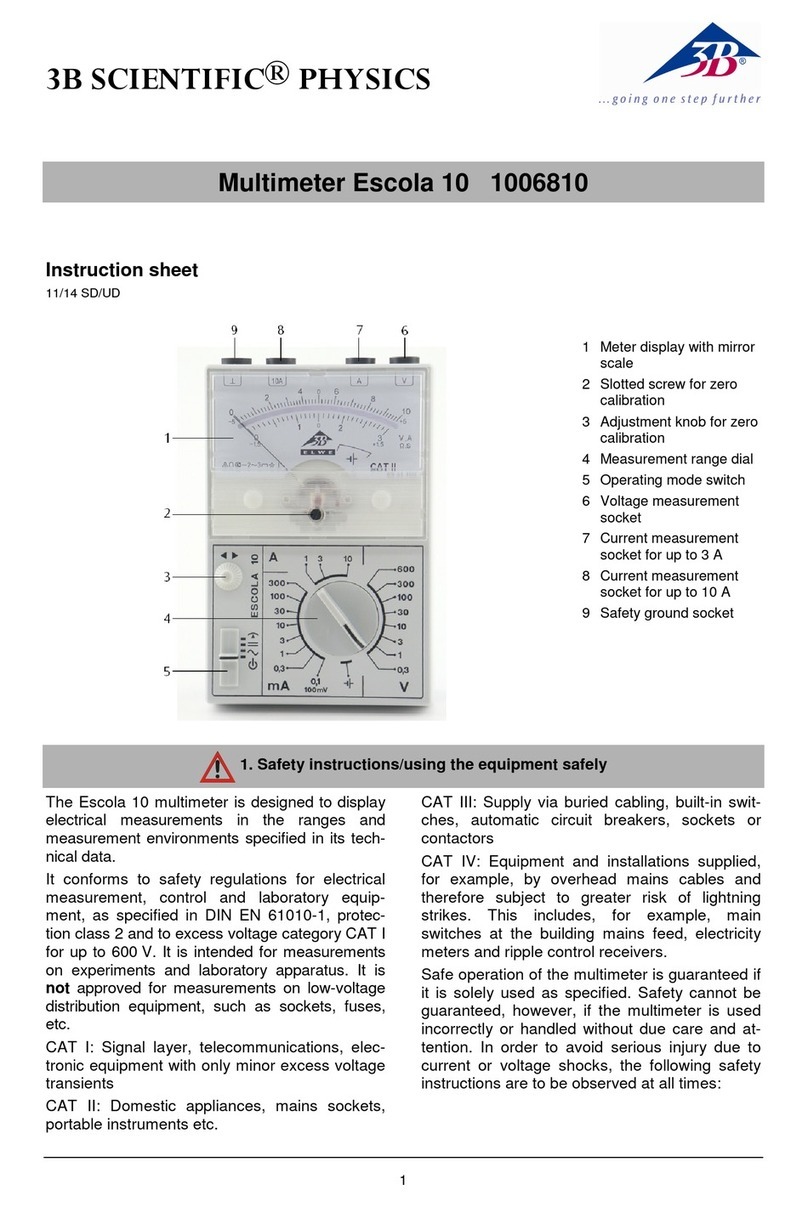
3B SCIENTIFIC PHYSICS Escola 10 1006810 User manual

3B SCIENTIFIC PHYSICS

3B SCIENTIFIC PHYSICS Escola 10 1006810 User manual

3B SCIENTIFIC PHYSICS Escola 10 User manual

3B SCIENTIFIC PHYSICS

3B SCIENTIFIC PHYSICS Escola 10 User manual

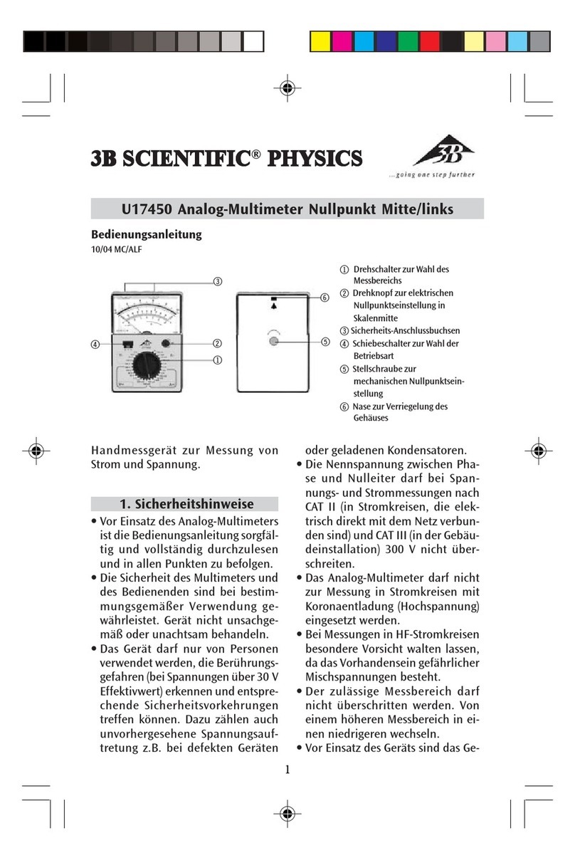
3B SCIENTIFIC PHYSICS U17450 User manual

3B SCIENTIFIC PHYSICS

3B SCIENTIFIC PHYSICS U17450 User manual

3B SCIENTIFIC PHYSICS Escola 2 1006811 User manual

3B SCIENTIFIC PHYSICS

3B SCIENTIFIC PHYSICS Escola 2 1006811 User manual

3B SCIENTIFIC PHYSICS Escola 10 User manual

3B SCIENTIFIC PHYSICS

3B SCIENTIFIC PHYSICS Escola 10 User manual

3B SCIENTIFIC PHYSICS 1017895 User manual

3B SCIENTIFIC PHYSICS

3B SCIENTIFIC PHYSICS 1017895 User manual

3B SCIENTIFIC PHYSICS Escola 30 User manual

3B SCIENTIFIC PHYSICS

3B SCIENTIFIC PHYSICS Escola 30 User manual

3B SCIENTIFIC PHYSICS Escola 30 User manual

3B SCIENTIFIC PHYSICS

3B SCIENTIFIC PHYSICS Escola 30 User manual

3B SCIENTIFIC PHYSICS E 1006809 User manual

3B SCIENTIFIC PHYSICS

3B SCIENTIFIC PHYSICS E 1006809 User manual

Popular Multimeter manuals by other brands

Monacor DMT-4010RMS instruction manual

Monacor

Monacor DMT-4010RMS instruction manual

Albercorp Cellcorder instruction manual

Albercorp

Albercorp Cellcorder instruction manual

Extech Instruments EX520 user guide

Extech Instruments

Extech Instruments EX520 user guide

Lovato DMG600 instruction manual

Lovato

Lovato DMG600 instruction manual

Triplett 1201 instruction manual

Triplett

Triplett 1201 instruction manual

Circuit-test DMR-1100 owner's manual

Circuit-test

Circuit-test DMR-1100 owner's manual

Greenlee 93-97 instruction manual

Greenlee

Greenlee 93-97 instruction manual

Greenlee CM-600 instruction manual

Greenlee

Greenlee CM-600 instruction manual

EMG 1464 Guide

EMG

EMG 1464 Guide

Major tech MT1877IV instruction manual

Major tech

Major tech MT1877IV instruction manual

Hanna HI 96711 instruction manual

Hanna

Hanna HI 96711 instruction manual

Swema 3000 manual

Swema

Swema 3000 manual

Milwaukee 2231-20 4-20 Repair service instructions

Milwaukee

Milwaukee 2231-20 4-20 Repair service instructions

Klein Tools MM700 instruction manual

Klein Tools

Klein Tools MM700 instruction manual

Owon XDM1241 user manual

Owon

Owon XDM1241 user manual

REED ST-9918T instruction manual

REED

REED ST-9918T instruction manual

Mastech MY67 instruction manual

Mastech

Mastech MY67 instruction manual

Amprobe ac68C user manual

Amprobe

Amprobe ac68C user manual

manuals.online logo
manuals.online logoBrands
  • About & Mission
  • Contact us
  • Privacy Policy
  • Terms and Conditions

Copyright 2025 Manuals.Online. All Rights Reserved.