3DHS Bigfoot 84" User manual

3DHobbyShop.com
Bigfoot 84” Assembly Manual
Thank you for purchasing this 3DHobbyShop ARF RC aircraft. If you have any issues, questions,
concerns or problems during assembly, please contact our tech department at:
[email protected] or 717-814-5316 10am-4pm Eastern Monday – Thursday.
SAFETY in Assembly
During assembly of this aircraft, you will be asked to use sharp knives, hot irons, and hobby adhesives.
Please follow all safety procedures recommended by the manufacturers of the products you use, and
always follow these important guidelines:
ALWAYS protect your eyes when working with adhesives, knives, or tools, especially power tools. Safety
glasses are the best way to protect your eyes.
ALWAYS protect your body, especially your hands and fingers when using adhesives, knives, or tools,
especially power tools. Do not cut toward exposed skin with hobby knives. Do not place hobby knives on
tables or benches where they can roll off or be knocked off.
ALWAYS have a first-aid kit handy when working with adhesives, knives, or tools, especially power tools.
ALWAYS keep hobby equipment and supplies out of the reach of children.

SAFETY in Flying
ALWAYS fly your aircraft in a safe area, away from spectators.
ALWAYS fly your aircraft in a safe manner, within your control.
NEVER fly too close to yourself.
ALWAYS wear eye protection while operating your model aircraft.
ALWAYS keep your hands and body clear of propellers.
ALWAYS observe lipoly battery safety procedures.
ALWAYS handle gasoline in a safe manner.
ALWAYS perform a ground test and range check of your radio system before flying.
REQUIRED ITEMS
CA Glue
Canopy Glue
30 Minute Epoxy Glue (NOT 5-minute Epoxy)
Hobby Knife
Phillips Screwdriver
Set Metric Allen Wrenches
Small Pliers
Wire Cutters
Rubbing Alcohol
Paper Towels
Blue Loctite thread-locking adhesive
Dremel-type rotary tool
Small adjustable wrench or wrench set
IMPORTANT NOTE: 3DHS Recommends ONLY High-Torque, Digital, Metal-gear Servos for this
aircraft. Suitable part numbers include Hitec HS-7955TG,and HS-7954SH. DO NOT attempt to use
nylon-geared servos on this airplane.
THIS AIRCRAFT IS NOT A TOY! IT IS A HIGH PERFORMANCE AEROBATIC AIRCRAFT AND
IMPROPER SETUP AND/OR USE COULD RESULT INJURY OR DEATH.
Assembly Instructions
UNPACK
Unpack your airplane and examine the components. Check for damage of any kind. If you find any
damage, contact 3DHobbyShop and report the damage.
COVERING SEAMS
There are many seams in the covering on this aircraft where one color meets another. We recommend
using a covering iron or trim sealing tool to go over all of the covering seams on your Bigfoot. This will
help to prevent any peeling of the covering. Repeat this periodically.

WRINKLES
Your Bigfoot was packed at the factory without any wrinkles in the covering. You may notice some
wrinkles now; more likely, you will notice a few in a day or two or the first time you take the plane out to
the flying field. These wrinkles are the result of wood shrinkage and/or expansion. Balsa wood changes
size and shape slightly as it is exposed to varying humidity in the air. This is a natural property of balsa
wood. As your airplane adjusts to the weather in your part of the world, wrinkles may appear and
disappear.
Wrinkles may be removed with the gentle application of heat to the covering material on your airplane,
using an iron and/or heat gun. Apply the heat gently: the covering material will shrink as you apply the
heat, and this will remove the wrinkles. BE CAREFUL! Too much heat applied too quickly can damage
the covering, either by causing it to pull away from the wood at seams and corners or even by melting it.
Wrinkles do not affect flight performance.
COVERING MATERIAL
Your Bigfoot is covered with genuine OraCover material. If you need to repair sections, matching
covering is sold at most hobby stores under the “UltraCote” brand.
Using a sharp hobby knife, a small-tip soldering iron, or a hot knife, remove the covering material over the
door and window openings on the fuselage.
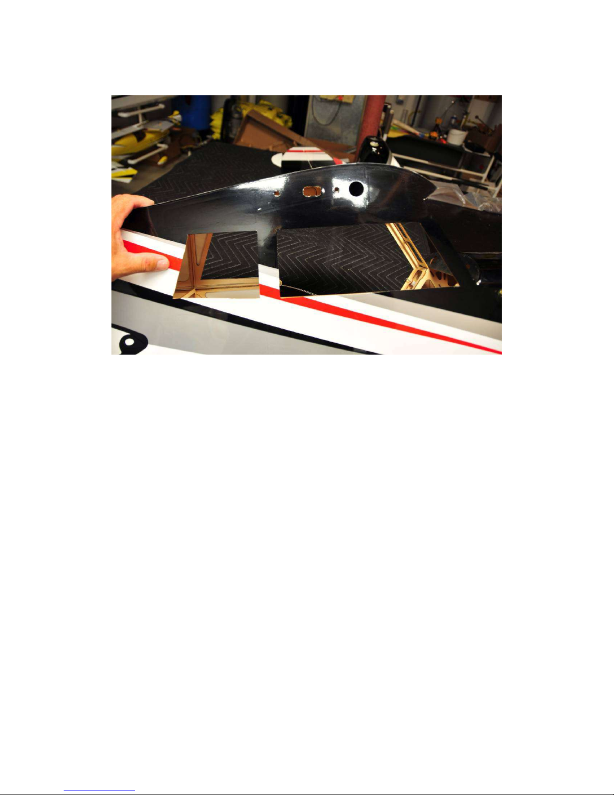
Also remove the covering over the wing spar, wing pin and retainer, and servo wire openings as shown.
Remove the covering over the horizontal stabilizer slot and the rear servo openings as needed. NOTE:
Bigfoot includes two rudder servo mounts, one in the rear on the right side (shown below) and one in the
cabin for pull-pull cable arrangement. If you are using an electric power don't cut the covering away from
the servo opening on the right side of the fuselage, since you will be mounting your rudder servo in the
front. For gas power, mount the rudder servo in the rear.

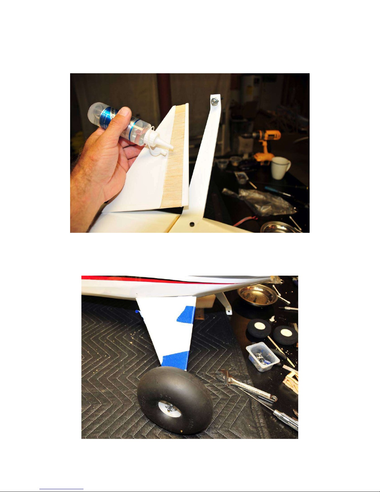
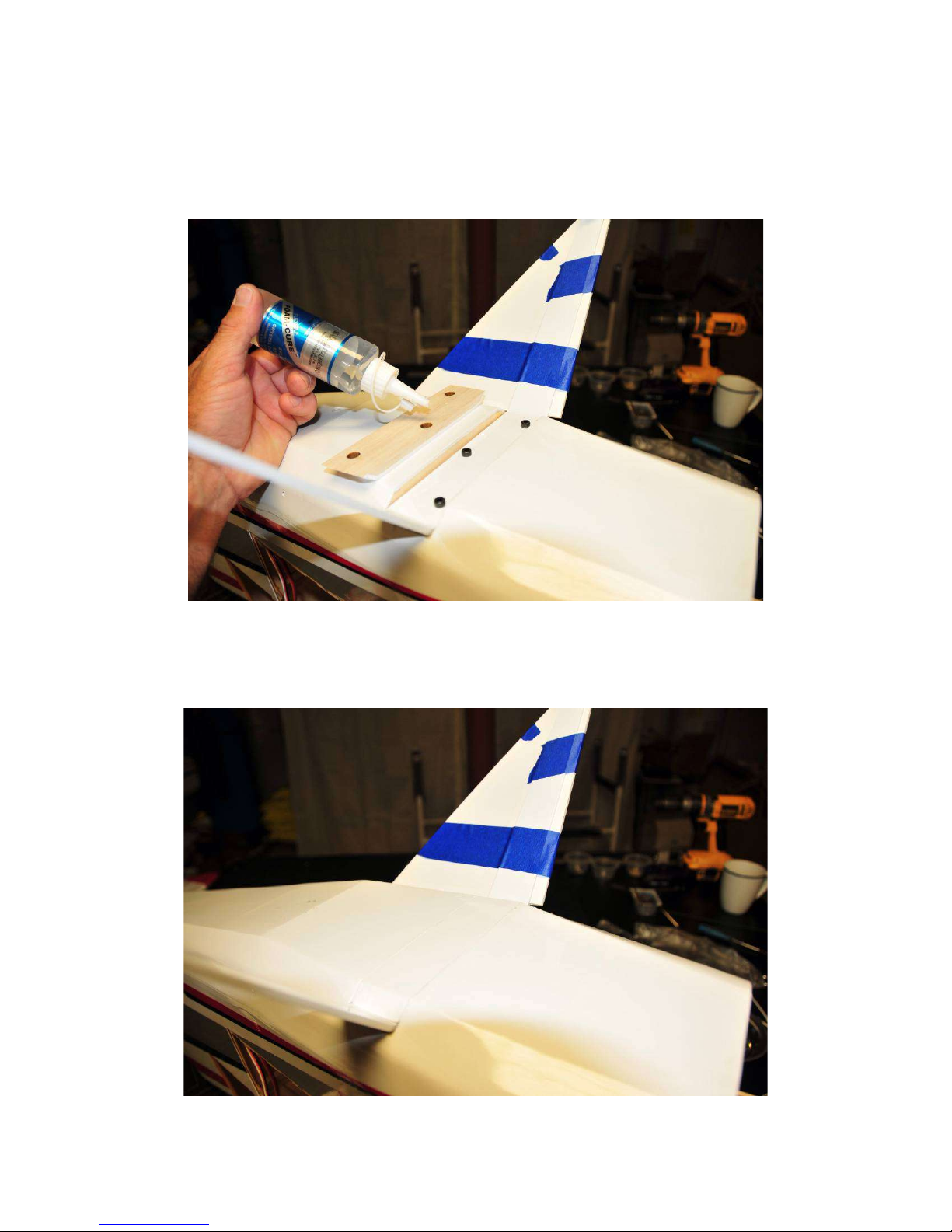
Test fit the vertical stabilizer into the slot but do not glue it yet. The fit should be snug. If it is too tight,
sand the bottom of the vertical stabilizer slightly.
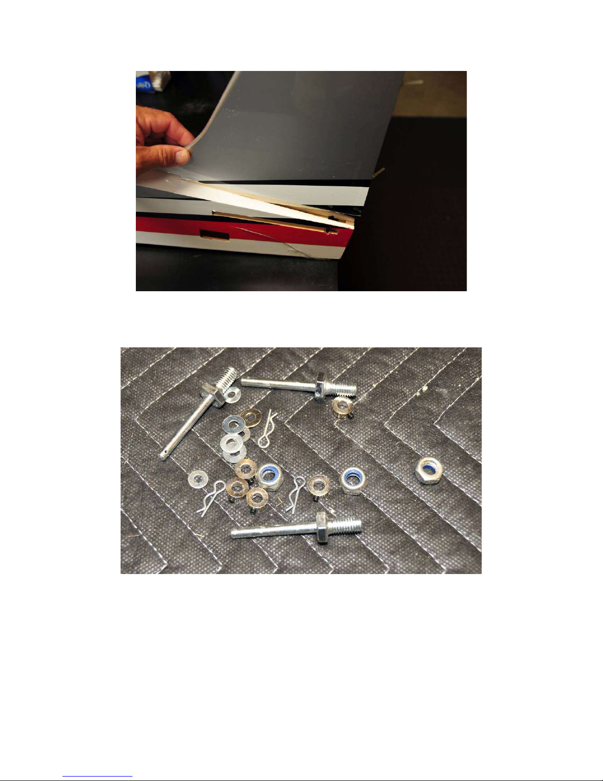
The main axles on the Bigfoot include a cross-drilled hole in the end of the axle for positive retention of
the main wheels with a cross-pin.
Bolt the main axles onto the landing gear as shown.
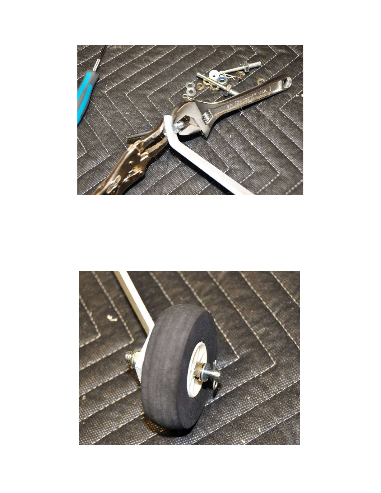
Your kit includes 3" wheels, which are a very lightweight option. If you wish to use them, install them onto
the axles along with wheels collars and pins as shown.
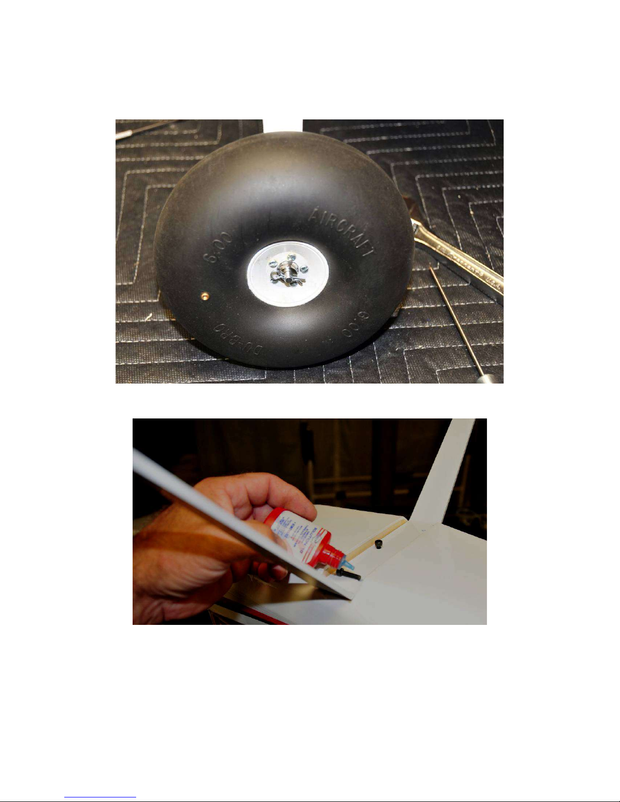
For a more scale look, you can use 6"-8" balloon tires, such as the pictured DuBro 6" balloon tires. Be
certain to use the cross pins as shown for wheel retention.
Attach the landing gear to the fuselage as shown, being sure to loctite these screws.
Use rubber cement or epoxy to attach the landing gear fairings.
Use tape to hold the fairings in place while the glue sets.
Use rubber cement or epoxy to install the landing gear cover plate on the bottom of the fuselage as
shown.
Table of contents
Other 3DHS Toy manuals


