manuals.online logo
Brands
  1. Home
  2. •
  3. Brands
  4. •
  5. 3DHS
  6. •
  7. Toy
  8. •
  9. 3DHS Extra 330SC User manual

3DHS Extra 330SC User manual

www.modellmarkt24.ch
1
95" Extra 330-E
Assembly Manual
Copyright 2017 Extreme Flight
www.modellmarkt24.ch
2
Please take a few moments to read this instruction manual before beginning assembly. We
have outlined a fast, clear and easy method to assemble this aircraft and familiarizing
yourself with this process will aid in a quick, easy build.
Please read the following paragraph before beginning assembly
of your aircraft!
THIS IS NOT A TOY! Serious injury, destruction of property, or even death may result
from the misuse of this product. Extreme Flight is providing you, the consumer, with a
very high quality model aircraft component kit, from which you, the consumer, will
assemble a flying model. It is beyond our control to monitor the finished aircraft you
produce. Extreme Flight RC will in no way accept or assume responsibility or liability for
damages resulting from the use of this user assembled product. This aircraft should be
flown in accordance with the AMA safety code. It is highly recommended that you join
the Academy of Model Aeronautics in order to be properly insured and operate your
model at AMA sanctioned flying fields only. If you are not willing to accept ALL liability
for the use of this product, please return it to the place of purchase immediately.
Extreme Flight RC, Ltd. guarantees this kit to be free of defects in materials and
workmanship for a period of 30 DAYS from the date of purchase. All warranty claims
must be accompanied by the original dated receipt. This warranty is extended to the
original purchaser of the aircraft kit only. Extreme Flight RC in no way warranties its
aircraft against flutter. We have put these aircraft through the most grueling flight tests
imaginable and have not experienced any control surface flutter. Proper servo selection
and linkage set-up is absolutely essential. Inadequate servos or improper linkage set up
may result in flutter and possibly the complete destruction of your aircraft. If you are not
experienced in this type of linkage set-up or have questions regarding servo choices, please
contact us at info@extremeflightrc.com or 770-887-1794. It is your responsibility to
ensure the airworthiness of your model.
www.modellmarkt24.ch
3
Extreme Flight designers Ben Fisher and Chris Hinson have long shared a mutual dream
to bring to market a Giant Scale airframe purpose designed for electric power.
Discussions and brainstorming sessions began even before the merger of Extreme Flight
and 3DHS. With the development, release and overwhelming enthusiasm for the Xpwr
line of motors and in particular the Xpwr 60, this vanity project has now become reality!
Extreme Flight is proud to present the 3DHS 95" EXTRA 330E!
The EXTRA 330E is a beautiful synergy of advanced composite materials implementation,
extreme weight reduction measures and well informed aerodynamic choices all wrapped
around one of the most powerful, efficient and reliable electric power systems currently
available. Far from being fragile and hard to handle, the EXTRA 330E is strong where it
needs to be and can handle any of the aggressive maneuvers performed by its gas powered
siblings.
www.modellmarkt24.ch
4
Items needed for completion:
✓Masking tape
✓Hobby knife with #11 blades
✓Thin and medium CA. We highly recommend Mercury M5T thin and M100XF
medium formulas as well as the Mercury glue tips
✓30 minute epoxy. Pacer Z-Poxy is a long time favorite
✓Goop Silicon glue
✓Blue and Red Loctite
✓Electric drill with an assortment of small drill bits
✓Small flat head and Phillips head screw drivers
✓Standard and needle nose pliers
✓Side cutters
✓Metric ball driver or allen key set
✓Sanding block and sandpaper
✓5 x MKS HV-777A, HBL-380 X8 or comparable servos
✓Extreme Flight Socket Head Servo Screws
✓2 x 1.5” Extreme Flight aluminum servo arms for the ailerons
✓2 x 2” Extreme Flight aluminum arms for the elevators
✓1 x 4” Extreme Flight double aluminum arm for pull-pull rudder.
✓1 1.5" Extreme Flight aluminum servo arm if using push-pull rudder
✓2 x Extreme Flight 6” 20 awg Servo Extensions.
✓2 x Extreme Flight 12” 20 awg Servo Extensions.
✓1 24" Extreme Flight 20 awg Servo Extension.
✓2 x 36” Extreme Flight 20awg Servo Extensions. If you need to remove the stabs for
transport use 48" extensions.
✓1 36" Extreme Flight 20 awg servo extensions if using rear mounted rudder servo
and push-pull assembly
✓Extreme Flight Servo Safety Clips
✓4.5” Spinner
✓Xpwr 60 Brushless Outrunner
✓Castle Creations EDGE 160HV ESC running Firmware v4.22
✓Series wiring harness to hook up 2 batteries in series with your choice of connectors
✓Blazing Star XXL Standoff Set
✓Xoar 24X10 or 24X12 PJN Electric Prop
✓High quality High C rating 12S Lipo battereis 5000-8000 mah capacity
✓Heavy duty Velcro and Velcro straps to secure batteries.
✓Optional-Extreme Flight Anodized Washer sets to add some bling!
www.modellmarkt24.ch
5
Tips for Success:
1. Before starting assembly, take a few minutes to read the entire instruction manual
to familiarize yourself with the assembly process.
2. Go over all the seams on the aircraft with a covering iron on a medium heat setting.
Also, due to climate changes, wrinkles may develop in the covering. These are easily
removed with a little bit of heat. Use a 100% cotton tee-shirt and your heat gun and
heat the covering while gently rubbing the covering onto the wood with the t-shirt.
Be careful not to use too much heat as the covering may shrink too much and begin
to lift at the edges. Take your time, and a beautiful, paint-like finish is attainable.
3. Apply CA to high stress areas such as servo mounting trays, landing gear mounts,
anti-rotation pins, wing and stab root ribs, and motor box joints etc.
4. By the time your aircraft arrives at your door step, it will have been handled by a lot
of people. Occasionally, there are small dings or imperfections on some of the
surfaces. An effective method to restore these imperfections to original condition is
to use a very fine tipped hypodermic needle and inject a drop of water under the
covering material and into the ding in the wood. Apply heat to the area with a
sealing iron and the imperfection will disappear. Deeper marks may require that
this process be repeated a couple of times to achieve the desired result, but you will
be surprised at how well this technique works.
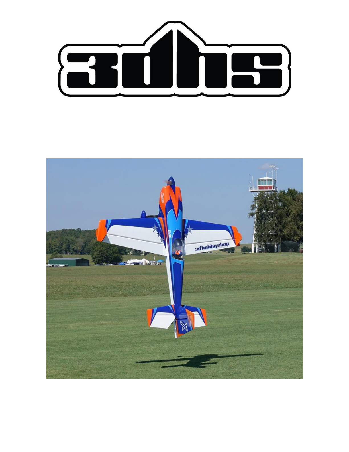
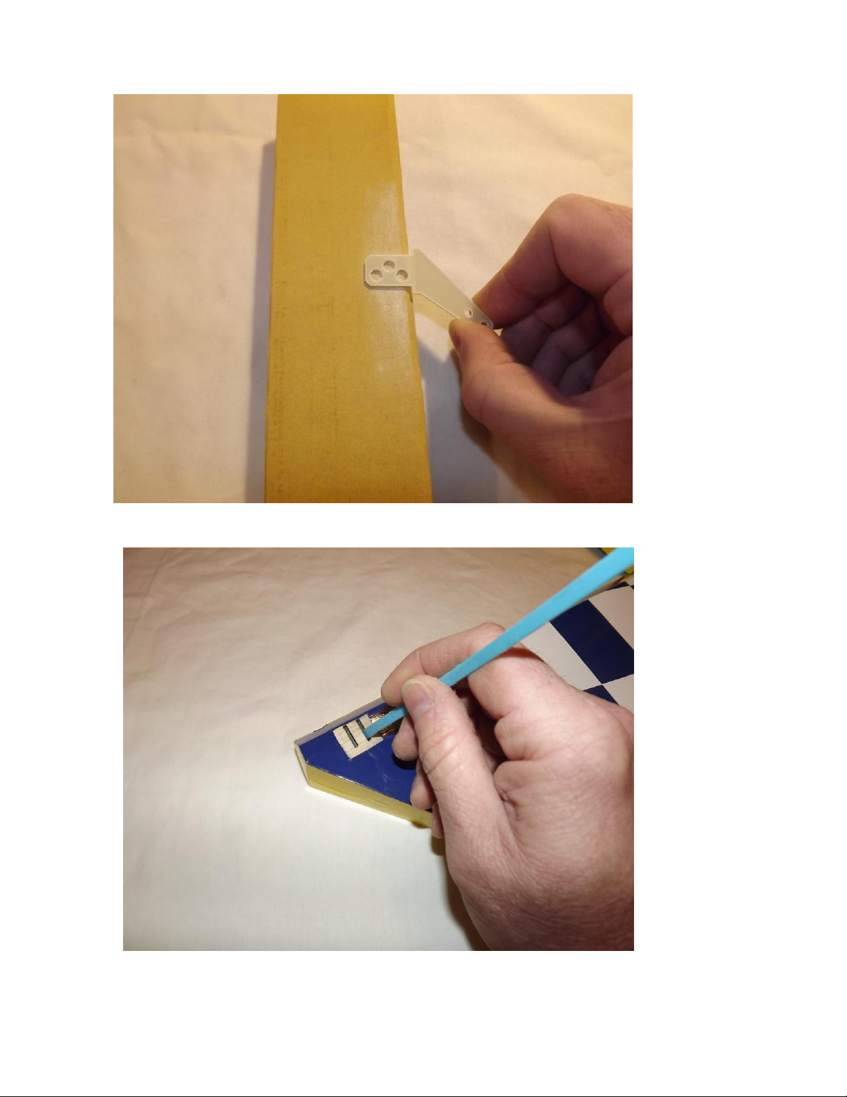
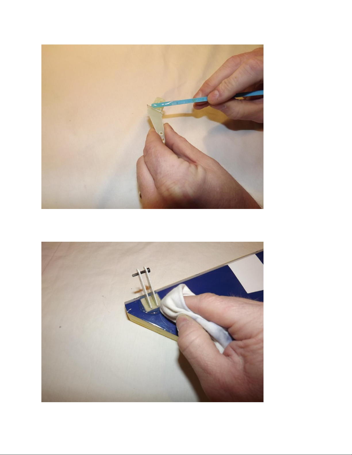
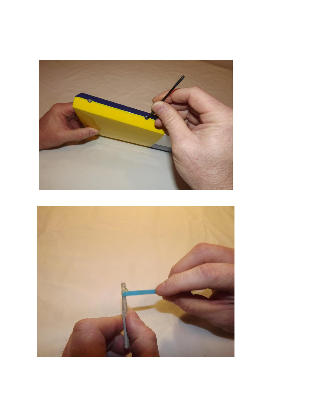
5. Use a high quality epoxy for installing the composite control horns and hinges. We
highly recommend Pacer Z-poxy. We are very pleased with the results and ease of
application and cleanup of this product.
6. Take the time to properly balance and trim your aircraft and set up rates and
exponential values. Your flying experience will be greatly enhanced once your plane
is properly dialed in.
Please Note: Because the assembly process is basically the same for all of the models in
this size, some photos may show parts from another model if it was deemed that these
photos better illustrated the assembly step.
www.modellmarkt24.ch
6
Let's begin!
Elevator Assembly
1. Locate the horizontal stabilizer/elevator assemblies as well as the composite control
horns and base plates from the elevator hardware package. Trial fit the assembly into
the slots in the elevator.
2. Trace around the base plate with a felt tipped marker.
www.modellmarkt24.ch
7
3. Remove the horn assembly and use a #11 blade to remove the covering from
inside the ink line you traced around the control horn base.
4. Wipe away the ink line with a cotton cloth or paper towel soaked in denatured
alcohol.
www.modellmarkt24.ch
8
5. Use sandpaper to scuff the portion of the horns and base plate that will be inserted
into the elevator.
6. Apply 30 minute epoxy to the elevator slots using a zip tie to ensure the slots are
filled will epoxy.
www.modellmarkt24.ch
9
7. Apply a generous amount of epoxy to the bottom of the G-10 control horns and
base plate.
8. Reinsert the assembly into the elevator and wipe away any excess epoxy with a
cloth and denatured alcohol. Place a 3mm bolt through the horns to help insure
proper alignment and set aside to dry. Repeat for the other elevator half.
www.modellmarkt24.ch
10
Note: There are several methods and adhesives that can be used for installing the
hinges. We will describe the way we do it as this method has proven itself over many
years of model building.
9. Mix a generous batch of 30 minute epoxy. Use a zip tie or an old pushrod to
thoroughly coat and fill the hinge holes on the stab with epoxy.
10. Next, coat one side of the hinges with epoxy and push the hinges into the holes of
the horizontal stab.
www.modellmarkt24.ch
11
11. Make sure the hinge pins are centered in the hinge gap and that they pivot 90
degrees to the stab.
12. Now coat the other side of the hinges as well as the hinge holes in the elevator
with epoxy and install the elevator onto the stab. Don’t forget to apply epoxy in the
hinge holes on the stab before installing the stab to the elevator.
www.modellmarkt24.ch
12
13. Use denatured alcohol and a cloth to remove all excess epoxy, especially on the
hinge pin. Make sure you have full deflection in both directions –once satisfied with
the results, set the surface aside to dry. After the hinges have dried thoroughly, pull
on the surfaces to make sure they are properly secured.
Note: Before installing the servos, it’s a good time to seal the hinge gap with a strip
of Ultracote or Blenderm tape. Also, I recommend that you dilute a small amount of
epoxy with a few drops of alcohol and apply a light coat to the inside of the stab and
to the servo mounting rib as well as to the root rib and mounting tabs to protect
against exhaust residue that can collect in these areas, especially if you plan to run a
smoke system.
www.modellmarkt24.ch
13
14. Before installing the elevator servos, temporarily install the servo arms and
electronically center the servos. Using the manufacturer supplied mounting
hardware, install the elevator servo with the output shaft toward the rear of the stab
and re-attach the servo arm.
15. Assemble the linkage and install as shown in the picture, using an Extreme
Flight 2 inch servo arm and the provided 3mm hardware.
www.modellmarkt24.ch
14
Wing Assembly
16. Locate the wing/aileron assemblies as well as the composite control horns and
base plates from the wing hardware package. Following the same procedure as
outlined with the elevator/stabs, install the control horns and hinges for both wings.
17. Attach a 12 inch EF 20 awg servo extension to the aileron servo lead and
secure with a servo safety clip or heat shrink tubing. Install the aileron servo
using the manufacturer provided hardware with the output shaft oriented
toward the leading edge of the wing. Electronically center your servo and install
the 1.5" EF servo arm and linkage as shown.
www.modellmarkt24.ch
15
Note: Before moving to the next step –it would be a good time to seal the hinge gaps
with a strip of Ultracote or Blenderm tape. Be sure to fully deflect the control
surface when sealing the gap to allow for full deflection once the gap is sealed.
Also, take a few minutes to go over the wings with a trim iron on a medium heat
setting to seal all the trim seams and remove any wrinkles in the covering. Use
caution and avoid excessive heat as this may cause the Ultracote to shrink too much
and lift at the seams.
Fuselage Assembly
18. Locate the Carbon Fiber main landing gear, 4 x 4mm bolts, lock nuts and
washers. Place the landing gear onto the landing gear plate on the bottom of the fuse
and align the 4 holes. Use a metric driver to attach the gear, securing with the 4
bolts, washers and nylon insert locking nuts inside the fuselage.
www.modellmarkt24.ch
16
19. Trail fit the landing gear fairings and when satisfied with fit secure with Goop
style silicon glue. Tape in position until dry.
20. Locate the 2 axles, 2 locking nuts, 2 washers, 2 wheels, 4 wheel collars and 2
wheel pants. Place the threaded portion of the axle through the hole in the landing
gear, place a washer onto the axle and secure the axle with a locking nut. Repeat this
process for the second wheel axle.
21. Install one wheel collar on the axel first in order to center the wheel in the wheel
pant. Next, slide the wheel onto the axel and secure the wheel with the second wheel
collar. Repeat this process for the remaining wheel. I usually place a short length of
fuel line on the end of the axle as shown for added security.
www.modellmarkt24.ch
17
22. Install each wheel pant using the supplied 3mm bolts and washers as shown in
the picture below. As always, use blue Loctite on ALL bolts.
www.modellmarkt24.ch
18
23. There are laser scribed marks for drilling for the motor mounting bolts for the
Xpwr 60. Drill to accommodate 6mm bolts. If using another make of electric motor
get the mounting template from the manufacturer and align on the laser inscribed
crosshairs on the front of the motorbox.
24. We highly recommend using the Blazing Star XXL Standoff Set to easily and
accurately mount your Xpwr motor to the Extra airframe. All necessary mounting
bolts are provided in the standoff package.
www.modellmarkt24.ch
19
25. There is a dedicated location with pre-installed blind nuts for mounting our
recommended ESC, the Castle Creations Edge 160HV. Simply bolt it in place with
3mm bolts. Remember the Loctite!
26. Take a few minutes to secure the motor wires, battery leads and receiver lead
and tidy up the installation to prevent chafing.
www.modellmarkt24.ch
20
27. Locate the rudder, the rudder control horns and the 2 slotted base plates. Use
sandpaper to scuff the bottom of the control horns as well as the side of the base
plates that will attach to the rudder. If using a direct drive push-pull linkage (which
is our recommended setup) only glue one set of horns in place on the right side of the
rudder (pilot's perspective) in the lower position using the same procedure as you did
with the elevators and ailerons.
28. As mentioned there are two locations available to install the rudder control
horns. If using the pull-pull system use the upper horn location as shown in this
photo.
www.modellmarkt24.ch

This manual suits for next models

1

Other 3DHS Toy manuals

3DHS SLICK 580 User manual

3DHS

3DHS SLICK 580 User manual

3DHS Extra 330-E User manual

3DHS

3DHS Extra 330-E User manual

3DHS Bigfoot 84" User manual

3DHS

3DHS Bigfoot 84" User manual

3DHS 92 Edge 540 V2 ARF User manual

3DHS

3DHS 92 Edge 540 V2 ARF User manual

Popular Toy manuals by other brands

Amewi 22617 Operation manual

Amewi

Amewi 22617 Operation manual

PIKO BR S 499 Instructions for use

PIKO

PIKO BR S 499 Instructions for use

LEGO CREATOR 10252 Building instructions

LEGO

LEGO CREATOR 10252 Building instructions

SIG SBACH XA-41 EP ARF Assembly manual

SIG

SIG SBACH XA-41 EP ARF Assembly manual

LEGO 60125 Assembly instruction

LEGO

LEGO 60125 Assembly instruction

EASYSKY Micro B-17 Flying Fortress manual

EASYSKY

EASYSKY Micro B-17 Flying Fortress manual

VTech Baby Toot-Toot Drivers Fire Engine Saves The Day user manual

VTech Baby

VTech Baby Toot-Toot Drivers Fire Engine Saves The Day user manual

Fisher-Price Rockin' Roadsters Sports Car instruction sheet

Fisher-Price

Fisher-Price Rockin' Roadsters Sports Car instruction sheet

GREAT PLANES Perfomance Series Sukhoi SU-31 1.60 ARF instruction manual

GREAT PLANES

GREAT PLANES Perfomance Series Sukhoi SU-31 1.60 ARF instruction manual

PIKO BR 247 TT Instructions for use

PIKO

PIKO BR 247 TT Instructions for use

Yamaha YZF-R1 Assembly instructions

Yamaha

Yamaha YZF-R1 Assembly instructions

Hasbro FurReal friends GoGo's Walkin' Puppies care guide

Hasbro

Hasbro FurReal friends GoGo's Walkin' Puppies care guide

Hasbro Transformers Cyberverse Adventures Bumblebee manual

Hasbro

Hasbro Transformers Cyberverse Adventures Bumblebee manual

timio TM02-02 user manual

timio

timio TM02-02 user manual

REVELL Airbus A320 Lufthansa Assembly manual

REVELL

REVELL Airbus A320 Lufthansa Assembly manual

Rovan LT-4WD instruction manual

Rovan

Rovan LT-4WD instruction manual

Fisher-Price GeoTrax instruction sheet

Fisher-Price

Fisher-Price GeoTrax instruction sheet

LeapFrog Speak & Learn Puppy Parents' guide

LeapFrog

LeapFrog Speak & Learn Puppy Parents' guide

manuals.online logo
manuals.online logoBrands
  • About & Mission
  • Contact us
  • Privacy Policy
  • Terms and Conditions

Copyright 2025 Manuals.Online. All Rights Reserved.