3M 2177 User manual

2177 Fiber Optic Closure
Instructions
July 2002
78-8130-5297-0-B

Contents:
1.0 General ....................................................................................................................................................3
2.0 Kit Contents ............................................................................................................................................3
3.0 Installation ..............................................................................................................................................4

1.0 General
The 3M™ 2177 Fiber Optic Splice Closure is used in new construction, direct buried applications for both
single-mode and multimode fiber optic cable splices. Cable entry ports can be field trimmed for butt splic-
ing. The rigid outer closure body provides mechanical protection and is filled with 3M™4442 High Gel
Reenterable Encapsulant.
A sealed, inner "protective shell" provides secondary moisture protection and prevents direct encapsulant
contact with exposed optical fibers. Reenterable encapsulant and a suitable splice organizer must be
ordered separately. Maximum closure capacity is 72 mechanical splices or 72 fusion splices using the 3M
2522 Splice Tray.
2.0 Kit Contents
Hose Clamps (4)
Fill Cap (1)
Double End Caps (2)
Snap-In Caps (2)
Closure Top with
Fill Ports (1)
Closure Bottom with
Spacer Web (1)
Funnel (1)
Protective Shell
6" (152 mm) Closure (1)
2.1 Additional Materials Required:
• 4442 High Gel Reenterable Encapsulant, 3000 gram units, (2 required)
• 2196 Universal Organizer Bracket
• 2522 Splice Organizer Tray
• Shield Connectors
• Ground Braid or Strap
• DR Tape, .75" (19 mm) wide
• Sheath Scuff
Foam Tape (1)

3.0 Installation
3.1 Splice Organizer Capacity:
Note: Maximum diameter of closure is 4.75"
(121 mm).
c. Install cables through end cap ports. Slide
end cap down cable to prevent interference
with cable preparations or splicing.
d. A flat end cap does not have to be pre-
installed.
3.4 Cable Preparation:
a. Scuff 9" (229 mm) of each cable sheath as
shown.
3.3 Protective Shell Installation:
a. Cut groove to allow cable entry.
Cut at Groove
b. Push cable through port(s) and slide protective
shell half down cable to prevent interference
with cable preparations or splicing.
b. Overwrap scuffed cable sheath with plastic
vinyl tape to prevent contamination during
cable cleaning or splicing.
3.5 Bonding and Grounding:
a. Open sheath per instructions supplied with
organizer. Degrease buffer tubes if necessary.
b. If cable shield is present, bond across splice
per splice organizer instructions.
c. If external ground is required, feed a #6 AWG
solid ground wire through one port on the
protective shell and end cap. Connect it to
ground and shield connector.
4.6"
(117 mm)
2.7"
(69 mm)
3.2 End Cap Installation:
a. Select desired port(s) and cut tip off cone end.
b. Slit the cone(s) to accommodate the diameter of
the cable. 4 slits at 90° intervals around the cir-
cumference of the cone are recommended.
Cut
Slits
ORGANIZER

3.6 Splicing:
a. Attach cable organizer bracket (3M 2196 or
equivalent) to cable.
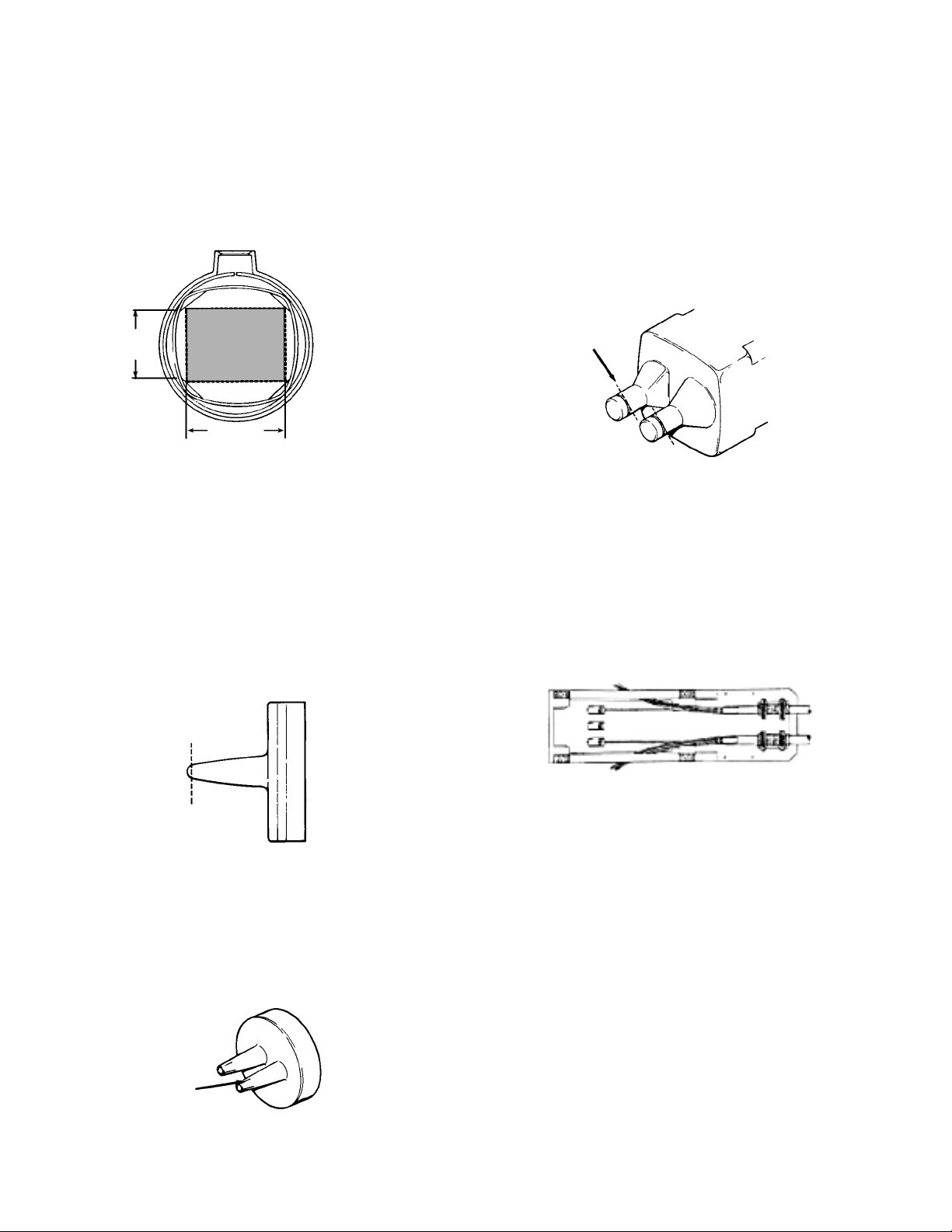
b. Place trays (3M 2522 or equivalent) and route
buffer tubes and fibers into the proper tray
following the instruction sheet.
c. Splice and test fibers per manufacturer's
instructions.
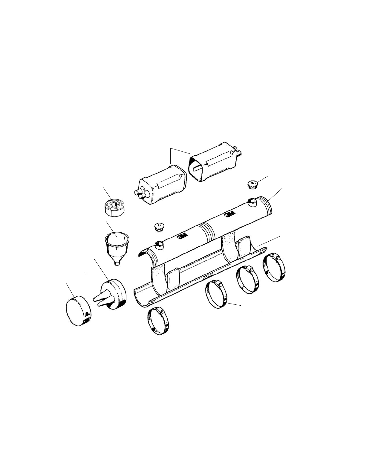
3.7 Protective Shell Assembly:
a. Remove plastic vinyl tape from cable sheaths.
b. Mark each cable 11" (279 mm) from the center
of the splice. At each location, wrap Foam
Tape around each cable. Taper sealant ends at
start and finish of wraps to prevent leakage.
See illustration for number of wraps.
Note: If external ground is required, embed the
ground wire within the Foam Tape Collar
wraps.
Foam Tape Wraps
Cable Diameter Required
.4" - .5" (10-13 mm) 2
.5" - .8" (13-20 mm) 1
.8" - 1.0" (20-25 mm) 0
c. Slide protective shell halves over splice area
and sheath collars (and external ground lead,
if applicable.) Push shell together until it
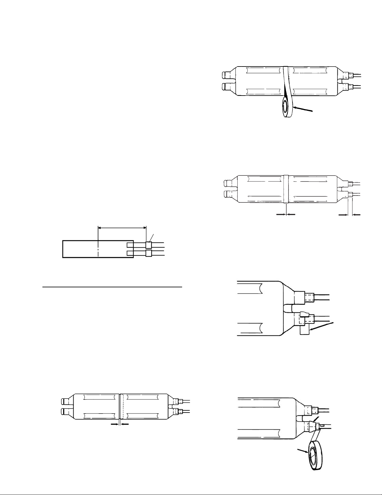
snaps into place. A 0.2" (5 mm) wide gap is
present when halves are correctly assembled.
d. Wrap center seam with foam tape and press
into place. Butt ends and trim excess.
e. Center shell, leaving approximately 1" (25 mm)
of Foam Tape exposed at each end.
f. Wrap 1 layer of Foam Tape at each shell port.
Center the tape on the protective shell port rim.
g. Completely overwrap Foam Tape with 2 half-
lap layers of highly stretched 3/4" (19 mm)
DR Tape white side out. Start DR Tape 1/2"
(13 mm) outside Foam Tape and continue to
taper of port.
11" (279 mm)
B Sealing Tape
0.2" (5 mm) Gap
Foam Tape
3/4" (19 mm) DR Tape
1 Layer of
Foam Tape
11.5" (292 mm)
11.5" (292 mm)
1" (5 mm)
1 Wrap Foam Tape

3.8 Closure Assembly:
a. Center lower closure half under protective
shell and assemble upper half (upper half has
fill ports) mating the tongue and groove.
Spacer Web strip ends will close, centering
protective shell.
b. Locate two hose clamps outboard from each
"3M" on the closure body and tighten. Set
end caps in grooves on closure body ends and
secure with 2 other hose clamps. Center clo-
sure over protective shell. Seal end caps to
cable sheaths with 2 half-lapped layers of DR
Tape. Start the half-lap layers on the cable
and tape up the cone.
d. Slightly incline one closure end about 1/2"
(13 mm). Place supports under the closure
for encapsulant filling.
Groove
Tongue
1/2"
(13 mm)
c. Position closure for burial on firmly packed
earth. Avoid sharp bends or kinks in the
cable.
e. Insert funnel into lower closure fill port.
(During filling, air will escape from higher
end.)
f. Two 3000 gram units of 3M 4442 High Gel
will be required to fill the closure.
g. Mix and pour encapsulant until closure is
completely filled and trapped air is removed.
Note: Carefully follow safety, health and envi-
ronmental information on container label
or Material Safety Data Sheet for the
encapsulant being used.
h. Close fill ports with the snap-in caps.
i. Check for any leaks. Tighten hose clamps or
retape as required. If leaks are observed, add
encapsulant to remove air voids.
j. Closure can be buried immediately.

3.9 Closure Reentry:
a. Remove hose clamps from closure and end caps. Remove any tape from end caps.
b. With a twisting motion, pull end caps from closure and slide down cable.
c. Grasping closure at one end, slowly separate halves from encapsulant. Do not use any tools to lever
against protective shell during reentry.
d. Remove cured encapsulant to expose protective shell.
e. Remove tape and sealant from protective shell ends and center section. Separate protective shell halves to
expose splices.
f. After completion of repair, reassemble as outlined in Sections 3.4 to 3.7. The protective shell can be
reused.
g. Place new 3M 4430 Spacer Web (3"W x 19"L) inside closure and reassemble closure as outlined in Section
3.8. End caps and sleeves can be reused.
Note: Be sure that the 4430 Spacer Web does not block the fill ports.
h. Fill closure with new encapsulant as outlined in Sections 3.8f to 3.8j.

IMPORTANT NOTICE
Before using this product, you must evaluate it and determine if it is suitable for your intended application. You assume all risks and liability
associated with such use.
Warranty; Limited Remedy; Limited Liability. This product will be free from defects in material and manufacture as of the date of pur-
chase. 3M MAKES NO OTHER WARRANTIES INCLUDING, BUT NOT LIMITED TO, ANY IMPLIED WARRANTY OF MERCHANTABILITY
OR FITNESS FOR A PARTICULAR PURPOSE. If this product is defective within the warranty period stated above, your exclusive remedy
shall be, at 3M’s option, to replace or repair the 3M product or refund the purchase price of the 3M product. Except where prohibited by
law, 3M will not be liable for any loss or damage arising from this 3M product, whether direct, indirect, special, incidental or conse-
quential regardless of the legal theory asserted.
Telecom Access Division
3M Telecommunications
6801 River Place Blvd.
Austin, TX 78726-9000
www.3M.com/telecom Printed on 50% recycled paper with
10% post-consumer
Litho in USA
Table of contents
Other 3M Enclosure manuals
Popular Enclosure manuals by other brands

Martin Audio
Martin Audio Architectual AM2 Technical specifications

Echostreams
Echostreams DSS212J quick guide

Kramer
Kramer K-POD302 quick start guide

SINGULARITY COMPUTERS
SINGULARITY COMPUTERS Eclipse Series Assembly manual

Ormazabal
Ormazabal PF-2015 Series General instructions

Icy Box
Icy Box IB-1820M-C31 manual