3M DBI SALA Flexiguard M100 User manual

© 3M 2020
1
A
3 51 2 4 6 7
C
8530911
USER INSTRUCTIONS
OSHA 1926.502 OSHA 1910.140
W H
B
8530874 17.5 ft.
(2.3 m) 10.0 ft. - 15.0 ft.
(3.0 m - 4.6 m) 568 lb.
(258 kg)
8530875 17.5 ft.
(2.3 m) 12.5 ft. - 20.0 ft.
(3.8 m - 6.1 m) 638 lb.
(289 kg)
8530876 17.5 ft.
(2.3 m) 15.0 ft. - 25.0 ft.
(4.6 m - 7.6 m) 727 lb.
(330 kg)
8530877 17.5 ft.
(2.3 m) 17.5 ft. - 30.0 ft.
(5.3 m - 9.1 m) 805 lb.
(365 kg)
8530882 27.5 ft.
(2.3 m) 15.0 ft. - 20.0 ft.
(4.6 m - 6.1 m) 504 lb.
(229 kg)
8530883 27.5 ft.
(2.3 m) 20.0 ft. - 25.0 ft.
(6.1 m - 7.6 m) 582 lb.
(264 kg)
8530884 27.5 ft.
(2.3 m) 25.0 ft. - 30.0 ft.
(7.6 m - 9.1 m) 660 lb.
(299 kg)
EN 795:2012
Type E
No. 2797
BSI
The Netherlands B.V.
Say Building
John M. Keynesplein 9
1066 EP
Amsterdam
Netherlands
No. 2797
BSI
The Netherlands B.V.
Say Building
John M. Keynesplein 9
1066 EP
Amsterdam
Netherlands
3MTM®TM
W
H
H
W
1 2
A A
A
8530869 1
8530870 2
8530871 3
8530872 4
8530873 5
8530918 6
8530919 7

2
2
A
B
C
D
E
G
H
J
K
F
G
I
K
H
H
K
K
A
M
F
C
D
E
L
L
N
N
N
N
3 4
A

3
5 6
A. B. C. D.
E. F. G.
A B C
7
AA
A
A
A
B
A
1 2
3 4

4
7
C
A
B
=360°
A
A
AB
X
=0°
5
6

5
8
B
A
B
A
B
C
H
R
L
X
X
1 2
3

6
9
A
B
A
10
C
A
BB
A
C
B
A
C
1 2 3
1 2
3

7
10
A
B
C
T
75 ft-lb
(102 N-m)
A
B
C
C
A
B
B
A
B
A
4 5
6 7
8

8
10
A
B
x2
11
A
B
9
1

9
11
A
B
AB
12
A
13
A
3
1
2
2
A
B
A
B
2 3

10
13
A
B
B
D
D
C
E
14
9515111 Rev. A
D
A
9514429 Rev. B
Mfrd. (yr, mo) Model No.:
Fabr. (aa, mm) N° de Modelo:
Serial no / N° de serie:
3M.com/FallProtection
Red Wing, MN 55066, USA
B
A B
C
D
≤ 6 kN
(1350 lbs.)
≤ 140 kg
(310 lbs.)
1x
9515102 Rev. D
2797
EN795:2012 "TYPE E"
OSHA 1926.502 & 1910.140
x
8530874 568 lbs. (258 kg)
8530875 638 lbs. (289 kg)
8530876 727 lbs. (330 kg)
8530877 805 lbs. (365 kg)
8530882 504 lbs. (229 kg)
8530883 582 lbs. (264 kg)
8530884 660 lbs. (299 kg)
#
lb.(kg)
A
AC
B
D
E
F
G
9515101 REV. A
=360°
=0°
C
A
B
C
9515122 REV. B
2x
2x
E
A

FORM NO: 5908278 REV: A 11
SAFETY INFORMATION
Please read, understand, and follow all safety information contained in these instructions prior to the use of this Flexiguard System.
FAILURE TO DO SO COULD RESULT IN SERIOUS INJURY OR DEATH.
These instructions must be provided to the user of this equipment. Retain these instructions for future reference.
Intended Use:
This Flexiguard System is intended for use as part of a complete fall protection or rescue system.
Use in any other application including, but not limited to, material handling, recreational or sports related activities, or other activities not described in
the User Instructions, is not approved by 3M and could result in serious injury or death.
This system is only to be used by trained users in workplace applications.
!WARNING
This Flexiguard System is part of a personal fall protection or rescue system. It is expected that all users be fully trained in the safe installation and
operation of the complete system. Misuse of this system could result in serious injury or death. For proper selection, operation, installation,
maintenance, and service, refer to all Product Instructions and all manufacturer recommendations, see your supervisor, or contact 3M Technical Service.
• To reduce the risks associated with transporting a Flexiguard system which, if not avoided, could result in serious injury or death:
- Ensure the system is properly secured or congured prior to transport. Refer to the User Instructions for detailed transportation requirements.
- Only transport below 5 mph (8 km/h) and at inclines of 10° or less, or as outlined in the User Instructions.
- Ensure the system will not contact overhead objects or electrical hazards while transporting or in use.
• To reduce the risks associated with working with a Flexiguard system which, if not avoided, could result in serious injury or death:
- Inspect all components of the system before each use, at least annually, and after any fall event, in accordance with the User Instructions.
- If inspection reveals an unsafe or defective condition, remove the system from service and repair or replace according to the User Instructions.
- Any system that has been subject to fall arrest or impact force must be immediately removed from service. Refer to the User Instructions or
contact 3M Fall Protection.
- The substrate or structure on which the system is attached/positioned must be able to sustain the static loads specied for the system in the
orientations permitted in the User Instructions or Installation Instructions.
- Do not exceed the number of allowable users as per the User Instructions.
- Never attach to a system until it is fully assembled, positioned, adjusted, and installed. Do not adjust the system while a user is attached.
- Never work outside the safe work area as dened by the User Instructions.
- Do not connect to the system while it is being transported or installed.
- Always maintain 100% tie-o when transferring between anchor points on the system.
- Use caution when installing, using, and moving the system as moving parts may create potential pinch points.
- Ensure proper lockout/tagout procedures have been followed when applicable.
- Only connect fall protection subsystems to the designated anchorage connection point on the system.
- When drilling holes for assembly or installation of the system, ensure no electric lines, gas lines, or other critical materials or equipment will be
contacted by the drill.
- Ensure that fall protection systems/subsystems assembled from components made by dierent manufacturers are compatible and meet the
requirements of applicable standards, including the ANSI Z359 or other applicable fall protection codes, standards, or requirements. Always
consult a Competent or Qualied Person before using these systems.
• To reduce the risks associated with working at heights which, if not avoided, could result in serious injury or death:
- Ensure your health and physical condition allow you to safely withstand all of the forces associated with working at height. Consult with your
doctor if you have any questions regarding your ability to use this equipment.
- Never exceed allowable capacity of your fall protection equipment.
- Never exceed maximum free fall distance of your fall protection equipment.
- Do not use any fall protection equipment that fails pre-use or other scheduled inspections, or if you have concerns about the use or suitability
of the equipment for your application. Contact 3M Technical Services with any questions.
- Some subsystem and component combinations may interfere with the operation of this equipment. Only use compatible connections. Consult
3M prior to using this equipment in combination with components or subsystems other than those described in the User Instructions.
- Use extra precautions when working around moving machinery (e.g. top drive of oil rigs) electrical hazards, extreme temperatures, chemical
hazards, explosive or toxic gases, sharp edges, or below overhead materials that could fall onto you or the fall protection equipment.
- Use Arc Flash or Hot Works devices when working in high heat environments.
- Avoid surfaces and objects that can damage the user or equipment.
- Ensure there is adequate fall clearance when working at height.
- Never modify or alter your fall protection equipment. Only 3M or parties authorized in by 3M may make repairs to the equipment.
- Prior to use of fall protection equipment, ensure a rescue plan is in place which allows for prompt rescue if a fall incident occurs.
- If a fall incident occurs, immediately seek medical attention for the fallen worker for the worker who has fallen.
- Do not use a body belt for fall arrest applications. Use only a Full Body Harness.
- Minimize swing falls by working as directly below the anchorage point as possible.
- If training with this device, a secondary fall protection system must be utilized in a manner that does not expose the trainee to an unintended
fall hazard.
- Always wear appropriate personal protective equipment when installing, using, or inspecting the device/system.
EN

12
;Prior to installation and use of this equipment, record the product identication information from the ID label in the
Inspection and Maintenance Log (Table 2) at the back of this manual.
;Always ensure you are using the latest revision of your 3M instruction manual. Visit the 3M website or contact 3M
Technical Services for updated instruction manuals.
PRODUCT DESCRIPTION:
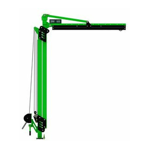
Figure 1 illustrates the 3M™ DBI-SALA®Flexiguard™ Modular Jib System M100 Adjustable Jib Boom. The M100 Jib System is
used to provide an adjustable Fall Arrest anchor point for a worker. These instructions cover use of the M100 Jib Boom, but use
of the M100 Jib System requires use of a Jib Base (sold separately) in addition to the Jib Boom. For a list of compatible Jib Base
models, see Figure 1.
Figure 2 illustrates components of the M100 Jib Boom. See Table 1 for Component Specications.
The Fixed Upright Assembly (A) serves as the main body of the Jib Boom. The Gusset (C) braces the Rail Assembly (D), which
lets the user move within the established work area. The Connection Eye (E) secures an SRD as a connection point for the user.
The Lifting Ring (F) is used to secure a chain or web strap for transporting the system. For B2 models, the Adjustment Channel
(M) enables height adjustment of the Jib Boom. For B1 models, the Adjustable Upright Assembly (B) enables height adjustment in
coordination with the Adjustment Winch (G). The cable of the Adjustment Winch is connected to the Jib Boom through a series of
pulleys, including the Lower Pulley of the Locking Assembly (I) and Upper Pulley (J). The Rotation Handle (H) allows for rotation
of the Jib Boom after placement. The Rotation Pin (K) secures the Jib Boom to prevent rotation. For B1 models, the Transportation
Pin (L) is used to secure the Jib Boom during transportation.
Table 1 – Specications
System Specications:
Capacity: One person with a combined weight (clothing, tools, etc.) of no more than 310 lb. (140 kg).
Anchorage: See the User Instructions for your Jib Base for more information on loading requirements of structure.
Dimensions: See Figure 1 for the dimensions of each M100 Jib Boom model.
Product Weight: See Figure 1 for the weight of each M100 Jib Boom model.
Maximum
Arresting Force:
All connecting subsystems (SRDs, Energy-Absorbing Lanyards, etc.) used with the Jib Boom must limit
the Maximum Arresting Force to 1,350 lbf (6.0 kN).
Maximum
Deection:
The Maximum Deection of the system during a fall arrest is measured to be 17.0 in. (432 mm). This
value should be added to any calculated Fall Clearance requirements for your connecting subsystem.
Certication: M100 Adjustable Jib Booms when used with 3M Jib Bases:
Portable Bases EN795.2012 OSHA 1926.502
OSHA 1910.140
8530869 Certied (Type E) Certied
8530870 Certied (Type E) Certied
8530873 Certied (Type B) Certied
Permanent Bases
8530871 Meets (Type A) Certied
8530872 (8530918, 8530919) Meets (Type A) Certied
Jib Boom
Compatibility:
The M100 Jib Boom models covered in these instructions are compatible only with those Jib Base models
listed on the front cover of these instructions.
Component Specications:
Figure 2
Reference Component Materials
Figure 2
Reference Component Materials
AFixed Upright Assembly Steel HRotation Handle Rubber, steel
BAdjustable Upright Assembly Steel ILocking Assembly Plastic, steel
CGusset Steel JUpper Pulley Plastic
DRail Assembly Aluminum KRotation Pin Steel
EConnection Eye Stainless steel,
plastic wheels LTransportation Pin Steel
FLifting Ring Steel, stainless steel MAdjustment Channel Steel
GAdjustment Winch Plastic, steel, aluminum NRotation Stop Steel

13
1.0 PRODUCT APPLICATION
1.1 PURPOSE: Jib Booms are designed to provide anchorage connection points for a Fall Protection system.
1.2 STANDARDS: Your Jib Boom conforms to the national or regional standard(s) identied on the front cover of these
instructions. If this product is resold outside the original country of destination, the re-seller must provide these
instructions in the language of the country in which the product will be used.
1.3 SUPERVISION: Installation of this equipment must be supervised by a Qualied Person1. Use of this equipment must be
supervised by a Competent Person2.
1.4 TRAINING: This equipment must be installed and used by persons trained in its correct application. This manual is to be
used as part of an employee training program as required by national, regional, or local standards. It is the responsibility
of the users and installers of this equipment to ensure they are familiar with these instructions, trained in the correct care
and use of this equipment, and are aware of the operating characteristics, application limitations, and consequences of
improper use of this equipment.
1.5 RESCUE PLAN: When using this equipment and connecting subsystem(s), the employer must have a rescue plan and
the means at hand to implement and communicate that plan to users, authorized persons3, and rescuers4. A trained, on-
site rescue team is recommended. Team members should be provided with the equipment and techniques to perform a
successful rescue. Training should be provided on a periodic basis to ensure rescuer prociency.
1.6 AFTER A FALL: If this equipment is subjected to fall arrest or impact forces, remove it from service immediately. Clearly
tag it “DO NOT USE”. See Section 5 for more information.
2.0 SYSTEM REQUIREMENTS
2.1 ANCHORAGE: Anchorage requirements vary with the fall protection application. Structure on which the Flexiguard
Anchorage System is placed or mounted must meet the Anchorage specications dened in Table 1.
2.2 FALL ARREST SYSTEM: Fall Arrest systems used with the Jib Boom must meet applicable Fall Protection standards,
codes, and requirements. Refer to the instructions included with your connecting subsystem for additional fall
requirements. The Fall Arrest system must incorporate a Full Body Harness and limit Arresting Force to the values
specied in Table 1.
2.3 FALL PATH AND SRD LOCKING SPEED: A clear path is required to assure positive locking of an SRD. Situations
which do not allow for an unobstructed fall path should be avoided. Working in confined or cramped spaces may not allow
the body to reach sufficient speed to cause the SRD to lock if a fall occurs. Working on slowly shifting material, such as
sand or grain, may not allow enough speed buildup to cause the SRD to lock.
2.4 HAZARDS: Use of this equipment in areas with environmental hazards may require additional precautions to prevent
injury to the user or damage to the equipment. Hazards may include, but are not limited to: heat, chemicals, corrosive
environments, high voltage power lines, explosive or toxic gases, moving machinery, sharp edges, or overhead materials
that may fall and contact the user or Personal Fall Arrest System.
2.5 FALL CLEARANCE: There must be sucient clearance below the user to arrest a fall before the user strikes the ground
or other obstruction. Fall Clearance is dependent on the following factors:
• Deceleration Distance • Worker Height • Elevation of Anchorage Connector
• Free Fall Distance • Movement of Harness Attachment Element • Connecting Subsystem Length
See the instruction manual of your connecting subsystem for specics regarding Fall Clearance calculation.
2.6 SWING FALLS: Swing Falls occur when the anchorage point is not directly above the point where a fall occurs (see Figure
3). The force of striking an object in a swing fall may cause serious injury or death. Minimize swing falls by working as
directly below the anchorage point as possible. Do not permit a swing fall if injury could occur. Swing falls will signicantly
increase the clearance required when a Self-Retracting Device or other variable length connecting subsystem is used.
2.7 SHARP EDGES: Avoid working where Lifeline or Lanyard components of the Fall Arrest system can contact or abrade
against unprotected sharp edges or abrasive surfaces (see Figure 4). Where contact with a sharp edge or abrasive surface
is unavoidable, cover the edge with protective material (A).
2.8 COMPONENT COMPATIBILITY: 3M equipment is designed for use with 3M-approved components and subsystems
only. Substitutions or replacements made with non-approved components or subsystems may jeopardize compatibility of
equipment and may aect the safety and reliability of the complete system.
2.9 CONNECTOR COMPATIBILITY: Connectors are considered to be compatible with connecting elements when they
have been designed to work together in such a way that their sizes and shapes do not cause their gate mechanisms to
inadvertently open regardless of how they become oriented. Contact 3M if you have any questions about compatibility.
Connectors must comply with EN 362. Connectors must be compatible with the anchorage or other system components.
Do not use equipment that is not compatible. Non-compatible connectors may unintentionally disengage (see Figure 5).
Connectors must be compatible in size, shape, and strength. If the connecting element to which a snap hook or carabiner
attaches is undersized or irregular in shape, a situation could occur where the connecting element applies a force to the
gate of the snap hook or carabiner (A). This force may cause the gate to open (B), allowing the snap hook or carabiner to
disengage from the connecting point (C).
1 Qualied Person: A person with a recognized degree, certicate, or professional standing, or who by extensive knowledge, training, and
experience has successfully demonstrated their ability to solve or resolve problems relating to fall protection and rescue systems to the extent
required by applicable national, regional, and local regulations.
2 Competent Person: One who is capable of identifying existing and predictable hazards in the surroundings or working conditions which are
unsanitary, hazardous, or dangerous to employees, and who has authorization to take prompt corrective measures to eliminate them.
3 Authorized Person: A person assigned by the employer to perform duties at a location where the person will be exposed to a fall hazard.
4 Rescuer: A person using the Rescue system to perform an assisted rescue.

14
2.10 MAKING CONNECTIONS: Snap hooks and carabiners used with this equipment must be self-locking. Ensure all
connections are compatible in size, shape and strength. Do not use equipment that is not compatible. Ensure all
connectors are fully closed and locked.
3M connectors (snap hooks and carabiners) are designed to be used only as specied in each product’s user’s instructions.
See Figure 6 for examples of inappropriate connections. Do not connect snap hooks and carabiners:
A. To a D-ring to which another connector is attached.
B. In a manner that would result in a load on the gate. Large throat snap hooks should not be connected to standard
size D-rings or similar objects which will result in a load on the gate if the hook or D-ring twists or rotates, unless the
snap hook complies is equipped with a 16 kN (3,600 lbf) gate. Check the marking on your snap hook to verify that it
is appropriate for your application.
C. In a false engagement, where features that protrude from the snap hook or carabiner catch on the anchor, and
without visual conrmation seems to be fully engaged to the anchor point.
D. To each other.
E. Directly to webbing or rope lanyard or tie-back (unless the manufacturer’s instructions for both the lanyard and
connector specically allows such a connection).
F. To any object which is shaped or dimensioned such that the snap hook or carabiner will not close and lock, or that
roll-out could occur.
G. In a manner that does not allow the connector to align properly while under load.

15
3.0 INSTALLATION
3.1 PLANNING: Plan your Fall Protection system prior to installation of the Jib Boom. Account for all factors that may aect
your safety before, during and after a fall. Consider all requirements, limitations, and specications dened in Section 2
and Table 1.
3.2 PLACING THE JIB BOOM: Before the Jib Boom can be used, it must be secured to a Jib Base. See Figure 7 for
reference. To secure the Jib Boom to a Jib Base:
1. Install and prepare the Jib Base (A) per its User Instructions. See Figure 1 for a list of compatible Jib Base models.
2. Secure the Rail Assembly and Gusset to the Upright Assembly using the 3/4 in. hardware provided. Torque hardware
to 130 ft-lb (176 N-m).
3. Connect the Jib Boom to the lifting device (forklift, overhead crane, etc.) that will transport the system. Insert the
Transportation Pin (B) before lifting the Jib Boom. Ensure that the Jib Boom is lifted by the Lifting Ring (A) located
atop the Gusset.
4. Transport the Jib Boom to the Jib Base. Lower the Jib Boom onto the Jib Base (A).
;When transporting the Jib Boom via forklift, driving speed must not exceed 5 mph (8 kpm).
5. After placement of the Jib Boom, rotate the Jib Boom to its desired work position by means of the Rotation Handle.
First, remove the Locking Pin (A) from the Rotation Handle. Then, lift the Rotation Handle to its perpendicular position
(B), and secure the handle by reinserting the Locking Pin (C).
6. To lock rotation of the Jib Boom, position the Locking Pin (A) over one of the holes on the Jib Base and then engage
the Locking Pin to secure the Jib Boom. Alternatively, the Locking Pin may be kept retracted to allow the Jib Boom to
rotate freely. Rotation Stops (B) may be inserted to limit System Rotation (X) within a desired range.
3.3 TRANSPORTING AFTER PLACEMENT: The Jib System may be moved after placement on some Jib Base models. For
more information, see the manufacturer instructions for your Jib Base model.
3.4 ADJUSTING THE HEIGHT OF THE JIB BOOM: After securing the Jib Boom to the Jib Base, you may adjust the
height of the Jib Boom. Height adjustment procedures vary based on your Jib Boom model. See Figure 1 for Jib Boom
identication.
• B1 MODELS: This series of M100 Jib Boom models is adjustable through means of an Adjustment Winch attached to
the base of the Jib Boom. See Figure 8 for reference.
INSTALLING THE ADJUSTMENT WINCH CABLE:
;This series of the M100 Jib Boom is shipped with the cable of the Adjustment Winch already routed through the
M100 Jib Boom. If the cable is already routed, skip to “Using the Adjustment Winch”.
1. Pay out the Cable (B) of the Adjustment Winch (A) by rotating the handle counterclockwise.
2. Extend the cable slowly as you thread it rst through the Upper Pulley (A), then around the Lower Pulley (B) of
the Locking Assembly. From the Lower Pulley, guide the cable back towards the Upper Pulley, then attach the cable
thimble to the 1/2 in. Anchor Bolt (C) between the spacer washers. Torque hardware to 60 ft-lb (81 N-m).
USING THE ADJUSTMENT WINCH:
3. After securing the cable through the system, the System Height (H) of the Jib Boom may be adjusted by turning
the handle of the Adjustment Winch. By turning the handle clockwise (R), the Jib Boom is raised. By turning the
handle counterclockwise (L), the Jib Boom is lowered. The height of the Jib Boom may be set anywhere between
the Side Plates (X) at the top and bottom of the Jib Boom. The Jib Boom may be raised until the Side Plates touch
at the top of the system.
• B2 MODELS: This series of M100 Jib Boom models is adjustable through means of the Adjustment Channel attached
to the Fixed Upright Assembly. See Figure 9 for reference. To adjust the height of the Jib Boom:
1. Remove the two Channel Fasteners (A) from the Adjustment Channel (B).
2. Set the Jib Boom to the desired height. Each hole in the Adjustment Channel adjusts the height of the system by
6.0 in. (15 cm).
3. Fasten the two Channel Fasteners (A) to secure the Adjustment Channel at its new height. Torque 5/8 in. hardware
to 75 ft-lb (102 N-m).
3.5 CONNECTING A SELF-RETRACTING DEVICE (SRD): To connect to the M100 Jib System, the user must rst connect
an SRD to the Jib Boom. See Figure 11 for reference. To connect an SRD to the Jib Boom:
1. Secure the top connector of your SRD (A) to the Connection Eye (B) on the Rail Assembly.
2. Secure the end connector of your SRD (B) to the D-Ring (A) on your Full Body Harness.
3. When using the SRD with the Jib System, stay within the Safe Working Area (A) of the Jib Boom. The user should
remain as directly below the Connection Eye as possible when using the system. For more information on safe work
area, see Section 4.
3.6 INSTALLATION AND USE OF THE FORK POCKET KIT (8530911): For B1 Jib Boom models, a Fork Pocket kit (sold
separately) may be secured to the Jib Boom to facilitate easy transport without use of a Jib Base or the D-Ring atop the
Gusset. See Figure 10 for reference. To connect the Fork Pockets to the Jib Boom and transport:
1. Remove the Roller Guard (A) from the base of the Upright Assembly (B). Once the Roller Guard is removed, place one
Forklift Blade (C) just beneath the Upright Assembly. Lift the Forklift Blade just enough to remove pressure on the
fasteners of the Upright Assembly.
2. Remove the Top Fastener (A) from the Steel Plate (B).
3. Place the Fork Pockets (C) on either side of the Jib Boom, ush against the Steel Plates (B) of the Upright Assembly,

16
with the top hole of each component aligned. Reinsert the Top Fastener (A) to secure, threading through both the
Fork Pockets and both the Steel Plates.
4. Remove the Bottom Fastener (A) from the Steel Plate (B). Repeat Step 3 with the Bottom Fastener to nish securing
the Fork Pockets (C) to the Upright Assembly.
5. Torque the 5/8 in. hardware of the Upright Assembly to 75 ft-lb (102 N-m).
6. Remove the forklift blade from the base of the Upright Assembly (B). Reinstall the Roller Guard (A) at the base of the
Upright Assembly. Verify that the Fork Pockets (C) are securely installed. The Tri-Screws located on the bottom of the
Fork Pockets should be facing downward.
7. To transport, insert the Forklift Blades (A) through the Fork Pockets, centering the blades on each Tri-Screw (B). Raise
the Forklift Blades to the top of the Fork Pocket tubes.
;When using the Fork Pockets, always approach from the front of the Jib Boom.
;Use caution when inserting the blades of the forklift through the Fork Pockets. Moving parts may create pinch
points and cause injury.
8. Tighten the Tri-Screws (B) at the base of each Fork Pocket tube to secure each tube to the Forklift Blades (A).
9. Secure the Fork Pockets to the forklift by threading a Chain (A) through each Fork Pocket Connection Ring (B) before
attaching the chain to the forklift. Remove any slack from the chain and secure using a chain link.
4.0 USE
4.1 BEFORE EACH USE: Verify that your work area and Fall Protection system meet all criteria dened in these instructions.
Verify that a formal Rescue Plan is in place. Inspect the system per the ‘User’ inspection points dened in the “Inspection
and Maintenance Log” (Table 2). If inspection reveals an unsafe or defective condition, or if there is any doubt about its
condition for safe use, remove the system from service immediately. Clearly tag the system “DO NOT USE”. See Section 5
for more information.
4.2 SAFE WORKING AREA: The Safe Working Area of the Jib Boom does not extend beyond the length of the Jib Boom
itself. See Figure 11.3 for reference. When using the M100 Jib System, the user should remain within the indicated Safe
Working Area (A). Leaving the Safe Working Area to an Outside Location (B) is dangerous and could result in serious
injury or death. When working on either side of the M100 Jib System, keep the anchor point as close overhead as
possible. If a rotation stop is in place on the jib mount, never work past that rotation stop.
5.0 INSPECTION
;After product has been removed from service, it may not be returned to service until a Competent Person conrms in
writing that it is acceptable to do so.
5.1 INSPECTION FREQUENCY: The product shall be inspected before each use by the user and, additionally, by a
Competent Person other than the user at intervals of no longer than one year. A higher frequency of equipment use
and harsher conditions may require increasing the frequency of Competent Person inspections. The frequency of these
inspections should be determined by the Competent Person per the specic conditions of the worksite.
5.2 INSPECTION PROCEDURES: Inspect this product per the procedures listed in the “Inspection and Maintenance Log”.
Documentation of each inspection should be maintained by the owner of this equipment. An inspection and maintenance
log should be placed near the product or be otherwise easily accessible to users. It is recommended that the product is
marked with the date of next or last inspection.
5.3 DEFECTS: If the Jib Boom cannot be returned to service because of an existing defect or unsafe condition, then either
destroy the system or contact 3M or a 3M-authorized service center about possible repair.
5.4 PRODUCT LIFE: The functional life of the Jib Boom is determined by work conditions and maintenance. As long as the
product passes inspection criteria, it may remain in service.
6.0 MAINTENANCE, SERVICE, and STORAGE
;Equipment that is in need of maintenance or scheduled for maintenance should be tagged “DO NOT USE”. These
equipment tags should not be removed until maintenance is performed.
6.1 CLEANING: Periodically clean the metal components of the Jib Boom with a soft brush, warm water, and a mild soap
solution. Ensure parts are thoroughly rinsed with clean water.
6.2 SERVICE: Only 3M or parties authorized in writing by 3M may make repairs to this equipment.
6.3 STORAGE: If applicable, store the Jib Boom and associated Fall Protection equipment in a cool, dry, clean environment
out of direct sunlight. Avoid areas where chemical vapors may exist. Thoroughly inspect components after extended
storage.
;Some Jib Base models used with the M100 Jib System are permanent. The Jib Boom may be removed from these
Jib Bases for storage or transport, but the Jib Base will have to remain.

17
7.0 LABELS and MARKINGS
7.1 LABELS: Figures 13 and 14 illustrate labels present on the Jib Boom. Figure 13 illustrates label locations and Figure
14 displays those associated labels. Labels must be replaced if they are not present or are not fully legible. Information
provided on each label is as follows:
AA) 3M Logo B) Applicable Standards C) Read all instructions.
D) Jib Boom Model Numbers and Weight Values
E) Maximum Arresting Force 1,350 lbf (6 kN)
F) Maximum Capacity - One user with a combined weight (clothing, tools, etc.) of no more than 310 lb. (140 kg).
BA) Manufactured (Year/Month) B) Model Number C) Serial Number
CA) Engage the Locking Pin to prevent rotation of the system.
B) Disengage the Locking Pin to enable full rotation of the system.
C) Maximum System Rotation is equivalent to the limits allowed by engagement or disengagement of the pin.
DA) 3M Logo
EA) Fork Pocket Use Instructions

Table 2 – Inspection and Maintenance Log
Inspection Date: Inspected By:
Components: Inspection: (See Section 5 for Inspection Frequency)User Competent
Person
Jib Boom
(Figure 2)
Inspect the entire system for damage, deformation, corrosion, and rust. Look
for cracks, bends, dents, or wear that could aect strength and operation of the
system.
Inspect all fasteners for damage or corrosion. Tighten as necessary.
Inspect all moving parts for chips, cracks, breaks, or worn areas that can cause
malfunction during operation.
Verify that all adjustment points (pins, bolts, tri-screws, adjusting screws, etc.)
are in full functional condition and are adjusted properly.
Fully lower the Jib Boom to take tension o the cable. Verify that the springs in
the Lower Pulley (I) are functional and free of rust or other obstructions. Verify
that the cable of the Adjustment Winch (G) has no frays or tearing. Ensure the
locking assembly engages.
Winch Assembly Inspect the Winch Assembly per 3M instruction manual 8511324.
Rollers and Bearings
(Figure 12) Grease the Rollers (A) and Bearings (B) of the Adjustable Upright Assembly for
B1 Jib Boom models. Ensure that all Roller locations are greased.
Anchor Connection
Points Ensure Anchor Connection Points are free of corrosion, cracks, or other
imperfections that my cause malfunction during operation.
Labels
(Figures 13 and 14) Verify that all labels are present and fully legible.
Fall Protection
Equipment Additional Fall Protection equipment that is used with the product should be
installed and inspected per the manufacturer instructions.
Serial Number(s): Date Purchased:
Model Number: Date of First Use:
Corrective Action/Maintenance: Approved By: Next inspection due:
Date:
Corrective Action/Maintenance: Approved By: Next inspection due:
Date:
Corrective Action/Maintenance: Approved By: Next inspection due:
Date:
Corrective Action/Maintenance: Approved By: Next inspection due:
Date:
Corrective Action/Maintenance: Approved By: Next inspection due:
Date:
Corrective Action/Maintenance: Approved By: Next inspection due:
Date:
Corrective Action/Maintenance: Approved By: Next inspection due:
Date:
Corrective Action/Maintenance: Approved By: Next inspection due:
Date:
Corrective Action/Maintenance: Approved By: Next inspection due:
Date:
Corrective Action/Maintenance: Approved By: Next inspection due:
Date:
Corrective Action/Maintenance: Approved By: Next inspection due:
Date:
Corrective Action/Maintenance: Approved By: Next inspection due:
Date:
Corrective Action/Maintenance: Approved By: Next inspection due:
Date:

FORMULARNUMMER: 5908278 REV: A 19
SIKKERHEDSOPLYSNINGER
Læs alle sikkerhedsoplysninger i denne brugsanvisning, og sørg for, at du forstår og følger disse, før du bruger dette Flexiguard-system.
UNDLADELSE HERAF KAN MEDFØRE ALVORLIG PERSONSKADE ELLER DØDSFALD.
Disse anvisninger skal udleveres til brugeren af udstyret. Opbevar denne vejledning til senere brug.
Anvendelsesformål:
Dette Flexiguard-system er beregnet til brug som en del af et komplet personligt faldsikrings- eller redningssystem.
Enhver anden brug end denne, herunder eksempelvis materialehåndtering, rekreative eller sportslige aktiviteter eller andre aktiviteter, der ikke er
beskrevet i brugs- eller installationsvejledningen, er ikke godkendt af 3M og kan medføre alvorlig skade eller død.
Dette system må kun benyttes af uddannede brugere til anvendelse på arbejdspladsen.
!ADVARSEL
Dette Flexiguard-system er en del af et personligt faldsikrings- eller redningssystem. Det forventes, at alle brugere er fuldt uddannet i sikker installation
og drift af hele systemet. Misbrug af dette system kan medføre alvorlig skade eller død. Jævnfør alle produktvejledninger samt alle producentens
anbefalinger, tal med din vejleder eller kontakt 3M’s tekniske service vedrørende korrekt valg, drift, installation, vedligeholdelse og servicering.
• For at reducere risici i forbindelse med transport af et Flexiguard-system, som, hvis de ikke undgås, kan medføre alvorlig skade
eller død:
- Sørg for, at systemet er korrekt sikret og kongureret inden transport. Der henvises til brugervejledningerne for detaljerede transportkrav.
- Transporter kun under 8 km/t (5 mph) og på stigninger på 10° eller mindre, som anført i brugervejledningen.
- Sørg for, at systemet ikke kommer i kontakt med overhængende genstande eller elektrisk fare under transport eller ved brug.
• For at reducere risiciene ved at arbejde med et Flexiguard-system, som, hvis de ikke undgås, kan medføre alvorlig skade eller død:
- Efterse alle komponenter i systemet før hver brug, mindst én gang om året og efter et eventuelt fald. Efterse systemet i overensstemmelse
med brugervejledningen.
- Hvis eftersynet afslører usikre eller defekte tilstande, skal systemet tages ud af drift og repareres eller udskiftes i overensstemmelse med
brugervejledningen.
- Enhver anordning, som har været udsat for faldstandsning eller kraftpåvirkninger, skal straks tages ud af brug. Se brugervejledningen, eller
kontakt 3M Fall Protection.
- Det grundlag eller den bygning, som dette system fastgøres til, skal være i stand til at modstå de statiske belastninger, der er speciceret for
systemet i de retninger, der er tilladt i brugervejledningen eller installationsvejledningen.
- Overstig ikke antallet af tilladte brugere i henhold til brugervejledningen.
- Tilslut aldrig til et system før det er fuldt samlet, positioneret, justeret og installeret. Juster ikke systemet, mens en bruger er tilkoblet.
- Arbejd aldrig uden for det sikre arbejdsområde, som det er deneret i brugervejledningen.
- Forbind ikke til systemet, mens det er ved at blive transporteret eller monteret.
- Bevar altid 100 % afsnøring, når der skiftes mellem systemets forankringspunkter.
- Vær forsigtig ved installation, brug og ytning af systemet, da bevægelige dele kan skabe potentielle klemmepunkter.
- Sørg for at korrekte lockout/tagout-procedurer bliver fulgt som foreskrevet.
- Man må kun tilkoble faldsikringsundersystemer til det angivne forankringsforbindelsespunkt på systemet.
- Ved boring af huller til fastgørelse eller installation af systemet, skal det sikres, at ingen elledninger, gasledninger eller andre kritiske materialer
eller udstyr kommer i kontakt med boret.
- Sørg for, at faldsikringssystemer/-undersystemer, der er samlet fra komponenter, der er fremstillet af forskellige fabrikanter, er kompatible
og opfylder kravene i relevante standarder, inklusive ANSI Z359 eller andre gældende regulativer, standarder for eller krav til faldbekyttelse.
Opsøg altid en kompetent eller kvaliceret person, før du anvender disse systemer.
• For at reducere risici i forbindelse med højdearbejde, som, hvis de ikke undgås, kan medføre alvorlig skade eller død:
- Sørg for, at dit helbred og din kondition gør dig i stand til sikkert at kunne modstå alle de kræfter, der er forbundet med højdearbejde. Rådfør
dig med din læge, hvis du har spørgsmål vedrørende din evne til at bruge dette udstyr.
- Overstig aldrig den tilladte kapacitet for dit faldsikringsudstyr.
- Overstig aldrig den maksimale faldafstand fra dit faldsikringsudstyr.
- Brug ikke faldsikringsudstyr, som ikke virker ved forudgående brug eller planlagte inspektioner, eller hvis du er bekymret for udstyrets brug
eller egnethed til det tilsigtede formål. Kontakt 3M’s tekniske service med eventuelle spørgsmål.
- Kombinationer med visse delsystemer og komponenter kan forstyrre driften af dette udstyr. Brug kun kompatible forbindelser. Rådfør dig med
3M, før du bruger dette udstyr sammen med andre komponenter eller delsystemer end dem, der er beskrevet i brugervejledningen.
- Vær særligt forsigtig, når du arbejder i nærheden af maskiner, som bevæger sig (f.eks. øverste drev på olieplatforme), elektriske stødfare,
ekstreme temperaturer, kemiske farer, eksplosive eller giftige gasser, skarpe kanter eller under overliggende materialer, som kan falde ned på
dig eller faldsikringsudstyret.
- Brug Arc Flash eller Hot Works (dvs. passende beskyttelses)-anordninger, når du arbejder i miljøer med ekstrem varme.
- Undgå overader og genstande, som kan beskadige brugeren eller udstyret.
- Sørg for tilstrækkelig faldafstand ved højdearbejde.
- Faldsikringsudstyret må aldrig modiceres eller ændres. Kun 3M eller parter, som 3M skriftligt har bemyndiget må foretage reparationer på
udstyret.
- Før brug af faldsikringsudstyret skal du sørge for at have en redningsplan, som muliggør hurtig redning i tilfælde af fald.
- Hvis der sker et fald, så søg straks lægehjælp for den faldne arbejdstager.
- Brug ikke et kropsbælte til anvendelser, der involverer faldsikring. Må kun benyttes med komplet kropssele.
- Svingfald kan minimeres ved så vidt muligt at arbejde lige under forankringspunktet.
- Hvis der øves med denne anordning, skal der benyttes sekundært faldbeskyttelsesudstyr på en sådan måde, at lærlingen ikke udsættes for
utilsigtet faldrisiko.
- Brug altid passende personlige værnemidler under installation, brug eller inspektion af enheden/systemet.
DA

20
;Inden udstyret monteres og tages i brug, skal produktidentikationsoplysningerne fra ID-mærkaten noteres i inspektions-
og vedligeholdelsesloggen (tabel 2) på bagsiden af denne manual.
;Sørg altid for, at du bruger den seneste udgave af din 3M-brugervejledning. Besøg 3M-webstedet, eller kontakt 3M's
tekniske service for at få opdaterede brugervejledninger.
PRODUKTBESKRIVELSE:
Figur 1 illustrerer 3M™ DBI-SALA®Flexiguard™-moduludliggersystemets justerbare M100-udliggerbom. M100-udliggersystemet
bruges til at tilvejebringe et justerbart faldsikringsforankringspunkt til en person. Denne vejledning dækker brug af
M100-udliggerbommen, men brug af M100-udliggersystemet kræver brug af en udliggerbase (sælges separat) ud over
udliggerbommen. Se en liste over kompatible udliggerbasemodeller i gur 1.
Figur 2 viser M100-udliggerbommens komponenter. Se tabel 1 – Komponentspecikationer.
Den faste lodrette samling (A) fungerer som hoveddelen i udliggerbommen. Vinkelforstærkningen (C) afstiver skinneenheden
(D), der lader brugeren bevæge sig inden for det etablerede arbejdsområde. Forbindelsesøskenen (E) sikrer en SRD som
et tilslutningspunkt for brugeren. Løfteringen (F) bruges til at fastgøre en kæde eller berstrop til transport af systemet.
For B2-modeller muliggør justeringskanalen (M) højdejustering af udliggerbommen. For B1-modeller muliggør den justerbare
lodrette samling (B) højdejustering i koordinering med justeringsspillet (G). Justeringsspillets kabel er forbundet til
udliggerbommen gennem en række taljer, herunder den nedre talje på låseenheden (I) og den øverste talje (J). Drejehåndtaget
(H) gør det muligt at dreje udliggerbommen efter placering. Rotationsstiften (K) holder udliggerbommen fast for at forhindre
rotation. For B1-modeller bruges transportstiften (L) til at fastgøre udliggerbommen under transport.
Tabel 1 – Specikationer
Systemspecikationer:
Kapacitet: Én person med en samlet vægt (tøj, værktøj m.v.) på højst 140 kg.
Forankring: Se brugervejledningen til din udliggerbase for ere oplysninger om strukturens belastningskrav.
Dimensioner: Se målene for hver M100-udliggerbommodel i gur 1.
Produktvægt: Se vægten på hver enkel M100-udliggerbommodel i gur 1.
Maksimal
standsekraft:
Alle tilsluttede delsystemer (SRD'er, energiabsorberende taljereb osv.), der bruges med udliggerbommen,
skal begrænse den maksimale standsekraft til 6,0 kN.
Maksimal
afbøjning:
Systemets maksimale afbøjning under faldstandsning måles til 432 mm. Denne værdi skal lægges til alle
beregnede krav om faldafstand for dit forbundne delsystem.
Certicering: Justerbare M100-udliggerbomme, når de anvendes sammen med 3M-udliggerbaser:
Portable baser EN795.2012 OSHA 1926.502
OSHA 1910.140
8530869 Certiceret (type E) Certiceret
8530870 Certiceret (type E) Certiceret
8530873 Certiceret (type B) Certiceret
Permanente baser
8530871 Opfylder (type A) Certiceret
8530872 (8530918, 8530919) Opfylder (type A) Certiceret
Udliggerbom-
kompatibilitet:
M100-udliggerbommodeller, der er omfattet af denne vejledning, er kun kompatible med de
udliggerbasemodeller, der er anført på forsiden af denne vejledning.
Komponentspecikationer:
Figur 2
Reference Komponent Materialer
Figur 2
Reference Komponent Materialer
AFast lodret samling Stål HDrejehåndtag Gummi, stål
BJusterbar lodret samling Stål ILåseenhed Plast, stål
CVinkelforstærkning Stål JØvre talje Plastik
DSkinneenhed Aluminium KRotationsstift Stål
EForbindelsesøsken Rustfrit stål, plasthjul LTransportstift Stål
FLøftering Stål/rustfrit stål MJusteringskanal Stål
GJusteringsspil Plast, stål, aluminium NDrejestop Stål
Table of contents
Languages:
Other 3M Lifting System manuals
Popular Lifting System manuals by other brands

AMGO
AMGO BP-9X Installation and service manual

Sunex Tools
Sunex Tools 6602ASJ owner's manual

Haklift
Haklift VAK6 Translation of the original instructions

Braun Corporation
Braun Corporation Millenium NL Series Service manual

Nussbaum
Nussbaum 4.50 SL Operating Instruction and Documentation

BlueSky Mast
BlueSky Mast 350G XL Series Quick reference sheet

Nova Technology International, LLC
Nova Technology International, LLC Standard Profile Truck Lock Series Owner & user manual

Pride
Pride Outlander Series owner's manual

Terex
Terex Genie GTH1215M-101 Service and repair manual

Space
Space SB 1396 E manual

rav
rav KP5.337W Translation of the original instructions

AMSAN
AMSAN AM-PSPL6 manual