TERRY Lifestyle User manual
Document No: XH00212
Issue: A
Date: 14/03/16
This installation manual is to be left on site behind a cover panel.
The test certificate, once filled in, must be returned to office.
Electrics & Fault Finding
ORIGINAL INSTRUCTIONS

Lifestyle Elecs & Fault Finding - XH00212 Issue: A Page 2 of 18
Lifestyle Elecs & Fault Finding - XH00212 Issue: A Page 3 of 18
Contents
Circuit Diagram Section .........................................................................................................4
Wiring Diagram 1 – Lifestyle Lift Wiring to P/Pack Circ. Board CE966 (XH00203E) ......5
Wiring Diagram 2 – Sling Signal Conversion .................................................................6
Wiring Diagram 3 – Sling Top Connector, Door, Light and Underpan Wiring ...............7
Trailing Cable Wiring Information (XH00213A) ...............................................................9
Wiring Diagram 4a – Sling Wiring Top Section (XH00209A) ........................................10
Wiring Diagram 4b – Sling Wiring Middle Section (XH00210B)....................................11
Wiring Diagram 4c – Sling Wiring Bottom Section (XH00211B) ...................................12
Wiring Diagram 5 – Remote Control and Door Controller...........................................13
Fault Finding ........................................................................................................................14
Phone Support Fault Finding............................................................................................14
Terry Lifestyle Fault Finding – Emergency Circuit ............................................................15
(Takes out all LED’s in Car User Display) ........................................................................15
Terry Lifestyle Fault Finding – Down Hold........................................................................16
(No Yellow LED’s in User Display) ...................................................................................16
Terry Lifestyle Fault Finding – Up Hold ............................................................................17
(No Green LED’s in User Display)....................................................................................17

Lifestyle Elecs & Fault Finding - XH00212 Issue: A Page 4 of 18
Circuit Diagram Section
•Wiring Diagram 1 – Lifestyle Lift Wiring to P/Pack Circuit Board
CE966 (XH00203E)
The Power-pack wiring loom contains logic for Emergency Dumping of the carriage.
The Emergency Dump Relay is controlled directly from the Emergency Dump Enable
Switch in the carriage along with the Down call button. The mains intrusion for the
Pump and Motor Unit can be found here.
•Wiring Diagram 2 – Sling Signal Conversion
This interface allows the UPSIG and DNSIG voltage levels to be converted from +5 to
+12V safely and provides an output to indicate that the lift is moving.
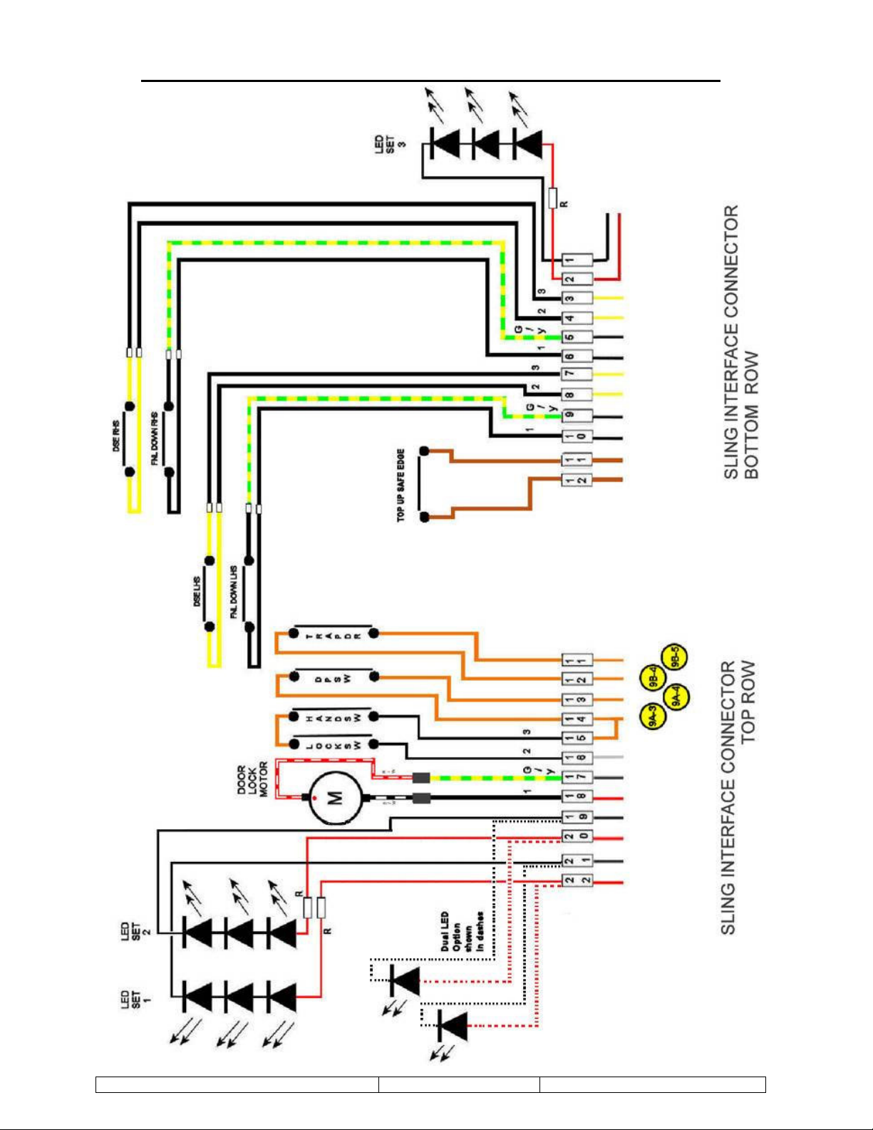
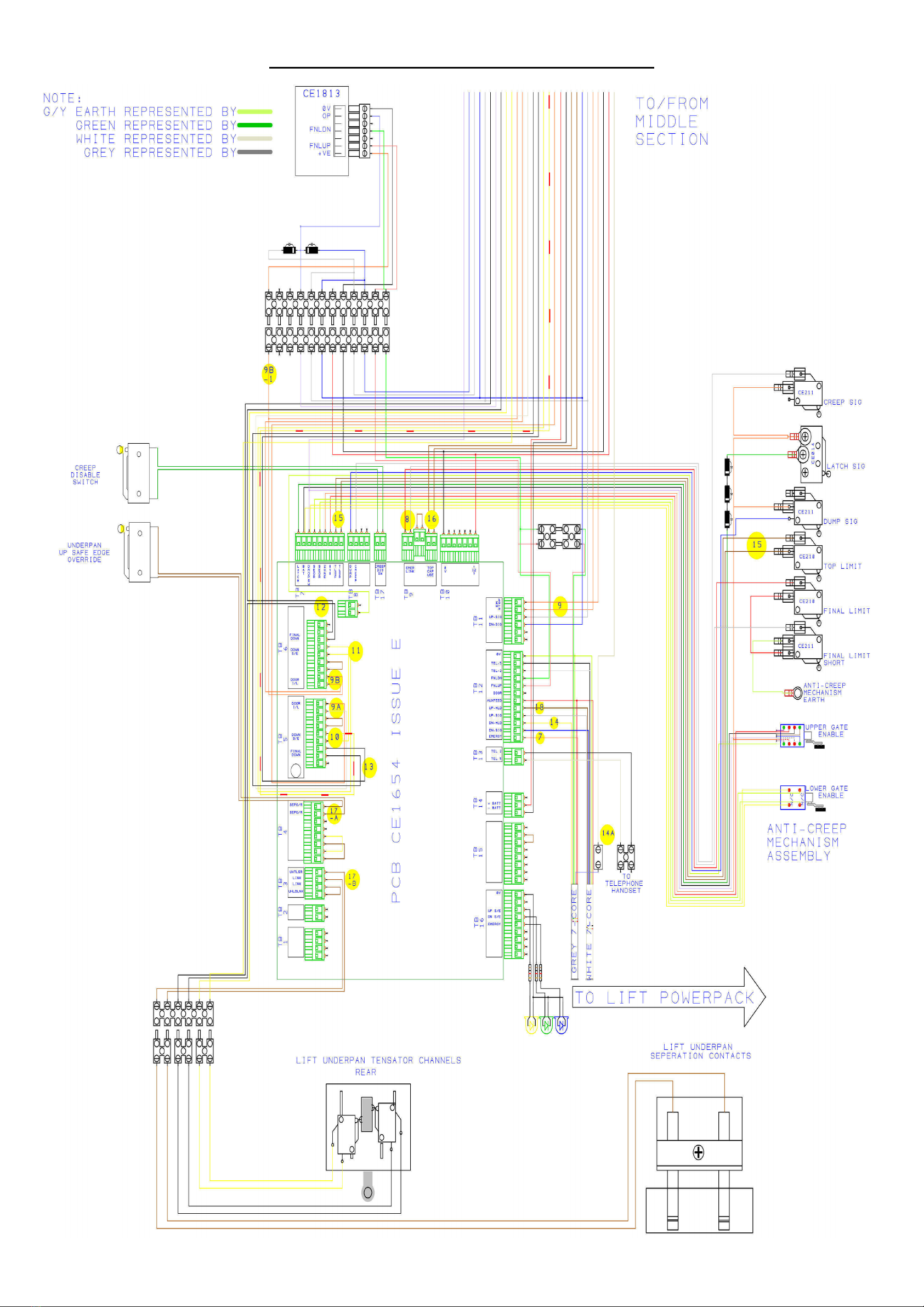
•Wiring Diagram 3 – Sling Top Connector, Door, Light and Underpan Wiring
This Top Connector is used to interface all cables that pass through the carriage roof on
the way to their final destinations.
•Trailing Cable Wiring Information (XH00213A)
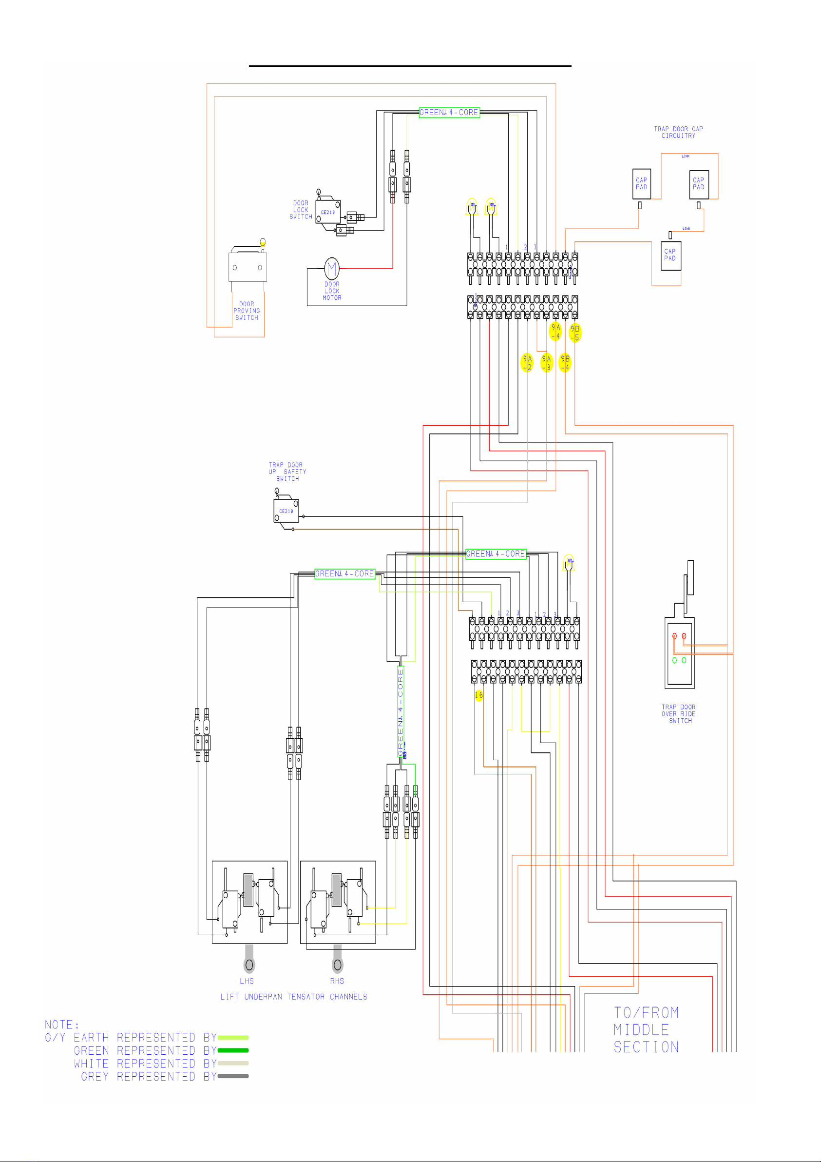
•Wiring Diagram 4a to 4c – Sling Main Loom
This loom provides the main distribution means of control and safety signals around the
carriage sling to the various control boards.
This diagram consists of three separate sections that are enlarged for easier viewing:
Wiring Diagram 4a - Sling Wiring Top Section (XH00209A)
Wiring Diagram 4b - Sling Wiring Middle Section (XH00210B)
Wiring Diagram 4c - Sling Wiring Bottom Section (XH00211B)
•Wiring Diagram 5 – Remote Control and Door Controller
This Controller is used to control the operation of the lifts carriage door and to on
interpret and action signals received from the Lifts Remote Control Transmitter devices.

Lifestyle Elecs & Fault Finding - XH00212 Issue: A Page 5 of 18
Wiring Diagram 1 – Lifestyle Lift Wiring to P/Pack Circ. Board CE966 (XH00203E)

Lifestyle Elecs & Fault Finding - XH00212 Issue: A Page 6 of 18
Wiring Diagram 2 – Sling Signal Conversion
Lifestyle Elecs & Fault Finding - XH00212 Issue: A Page 7 of 18
Wiring Diagram 3 – Sling Top Connector, Door, Light and Underpan Wiring

Lifestyle Elecs & Fault Finding - XH00212 Issue: A Page 8 of 18

Lifestyle Elecs & Fault Finding - XH00212 Issue: A Page 9 of 18
Trailing Cable Wiring Information (XH00213A)
Green/Yellow x 2 From each Trailing Cable
Black
White
Green + Link to MID Connector Strip vacant pin 12 (RH Gn Wire)
Pink + Link to MID Connector Strip vacant pin 11 (RH Pk Wire)
No Connection
Red x 2 From each Trailing Cable
Brown
Grey
Yellow
Blue
Orange
Purple – Fit to White wire with Choc Block from Emergency Dump
Relay
Lifestyle Elecs & Fault Finding - XH00212 Issue: A Page 10 of 18
Wiring Diagram 4a – Sling Wiring Top Section (XH00209A)

Lifestyle Elecs & Fault Finding - XH00212 Issue: A Page 11 of 18
Wiring Diagram 4b – Sling Wiring Middle Section (XH00210B)
Lifestyle Elecs & Fault Finding - XH00212 Issue: A Page 12 of 18
Wiring Diagram 4c – Sling Wiring Bottom Section (XH00211B)

Lifestyle Elecs & Fault Finding - XH00212 Issue: A Page 13 of 18
Wiring Diagram 5 – Remote Control and Door Controller
Lifestyle Elecs & Fault Finding - XH00212 Issue: A Page 14 of 18
Fault Finding
Before undertaking any detailed Fault Finding, confirm that the basic fault finding in the user
instructions has been undertaken.
Notes on fault finding
1) Before commencing fault finding using the flow chart:-
a) Check the status of all LED’s and fuses – and take any necessary action
b) Check door is closed
c) Ideally the lift should be in mid position i.e. off its limit switches
d) Note that LED’s on the sling board are only illuminated during the “Light on” period
(initiated by up/down/door signal) and when the user LED panel is disconnected.
2) Voltage checks indicate 13.6V this will vary according to battery condition and where it is
being measured – but under no load conditions should never be below 11.5V
3) If the alarm sounds when lift ascending the float switch is closed – detecting a full fluid
catch tank.
Phone Support Fault Finding
User Display LED's.
Note: key fob to enable the lift is optional.
Up Underpan obstruction – Green out.
Underpan Down obstruction – Yellow Out.
Trapdoor Up/Down obstruction; Door Lock Error; Proving Switch Error – Blue, Green &
Yellow Out.
Note: Top Limit red plunger sticking down will cause the Green LED’s to extinguish.
THE PRIMARY EMERGENCY LOWERING PROCESS WILL OPERATE WHEN THE
SPRUNG EMERGENCY DUMP SWITCH ON THE CARRIAGE CONTROL STATION IS
TURNED AND HELD IN THE CLOCKWISE DIRECT AND THE DOWN SWITCH IS
SIMULTANEOUSLY PRESSED. THE LIFT WILL SAFELY TRAVEL DOWNWARDS.
BACK-UP EXTERNAL EMERGENCY LOWERING ON A TERRY LIFESTYLE LIFT IS
ONLY TO BE CARRIED OUT IF SOMEONE IS TRAPPED INSIDE THE LIFT – not as a
means of down operation until an engineer can attend.
Lifestyle Elecs & Fault Finding - XH00212 Issue: A Page 15 of 18
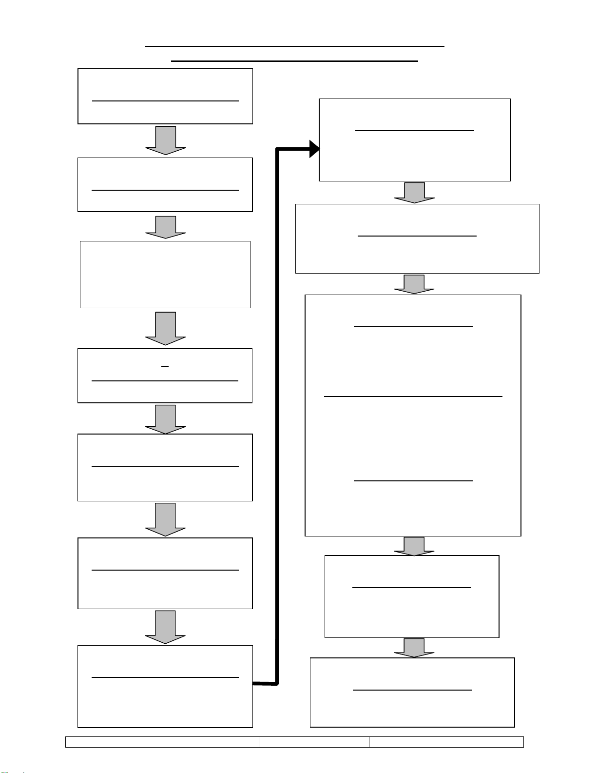
Terry Lifestyle Fault Finding – Emergency Circuit
(Takes out all LED’s in Car User Display)
•
Checks 1, 3, 4, 5, 6 – Done at Pwrpk PCB
•Checks 2, 2A, 7 – 9B – Done at Sling PCB
1
CE966 – Powerpack PCB
240V In
2
CE966 – Powerpack PCB
Charger (13.6V)
2A
i. Batteries (+13.6V)
ii. 5A Fuses on
Battery Negative
3
CE966 – Powerpack PCB
CB2 Resettable Fuse
4
CE966 – Powerpack PCB
TB4
STOP LINK
5
CE966 – Powerpack PCB
TB3 Pressure Switch
(Fitted on Ram)
7
CE1654 – Sling PCB
TB12 EMERGENCY
Trailing Cable
(Orange)
8
CE1654 – Sling PCB
TB9 Final Limit Switch Emergency Link
(White & Red)
9
CE1654 – Sling PCB
TB11 Pin 2 STOP on Call Station
Emergency Stop (Orange)
Checks Include Emergency Dump Relay
CE1798 – Radio Receiver PCB
TB7 Remote ON/OFF Fob
(Orange x 2)
Disabled when Smoke Alarm Activated
(2 Minutes 2, Beeps)
CE1654 – Sling PCB
TB11 Pin 1 STOP on Call Station
Emergency Stop
(Orange)
9A (1-4)
CE1654 – Sling PCB
TB5 Door Proving Switch &
Lock Micro-switch & Handle
(Orange & White)
9B(1-5)
CE1654 – Sling PCB
TB6 T/door S/E & o’ride system
(Orange)
6
CE966 – Powerpack PCB
TB5 EMERGENCY
Trailing Cable
(Orange)
Lifestyle Elecs & Fault Finding - XH00212 Issue: A Page 16 of 18
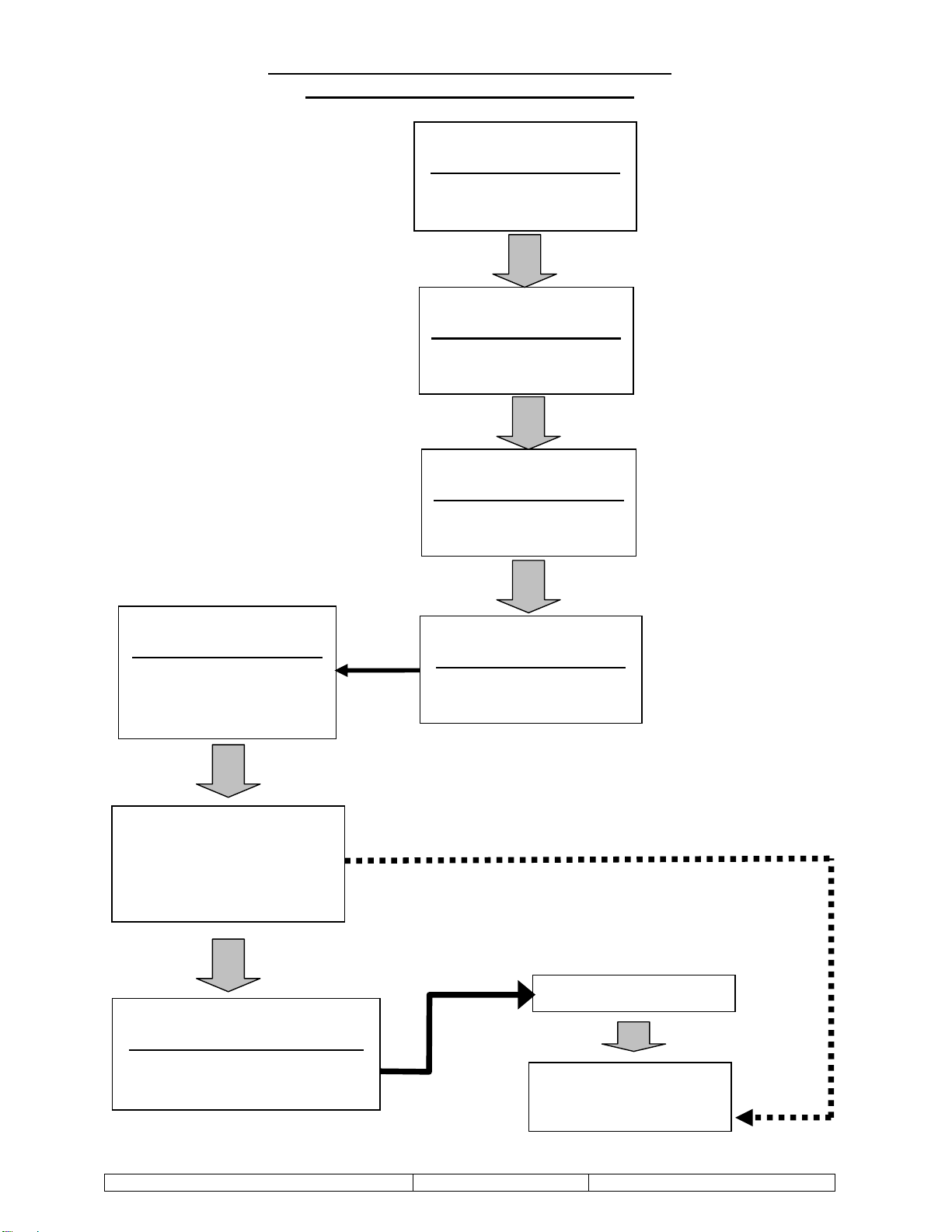
Terry Lifestyle Fault Finding – Down Hold
(No Yellow LED’s in User Display)
10*
CE1654 – Sling PCB
TB5 Down S/Edge
(Yellows)
11
CE1654 – Sling PCB
TB6 Down S/Edge
(Yellows)
12
CE1654 – Sling PCB
TB6 Final Down
(Blacks)
13
CE1654 – Sling PCB
TB5 Final Down
(Blacks)
14
CE1654 – Sling PCB
TB12 Down Hold
Trailing Cable
(Yellow)
14B
CE966 – Powerpack PCB
TB5 Trailing Cable
(Yellow)
DN Signal
Solenoid
+12V
14A
Powerpack & Carriage
Emergency Dump
System
•
Checks 10 – 14 done at Sling PCB
•Check 14A & 14B done at Pwrpk PCB *Check 10 includes
Emergency Dump Relay

Lifestyle Elecs & Fault Finding - XH00212 Issue: A Page 17 of 18
Terry Lifestyle Fault Finding – Up Hold
(No Green LED’s in User Display)
17A
CE1654 – Sling PCB
TB3 Underpan UP
Separation Switch
(Brown)
18
CE1654 – Sling PCB
TB12 Up Hold
Trailing Cable
(Brown)
17B
CE1654 – Sling PCB
TB4 Underpan Up
Separation O’ride
(Brown)
19
CE966 – Powerpack PCB
TB5 Up Hold
Trailing Cable
(Brown)
Up Signal
Final Relays
Motor
15
CE1654 – Sling PCB
TB7 Top Limit Switch
(Browns)
•
Checks 15 – 18 done at Sling PCB
•Check 19 done at Powerpack PCB
16
CE1654 – Sling PCB
TB9 TOP CAP S/E & Links
(Brown)

Lifestyle Elecs & Fault Finding - XH00212 Issue: A Page 18 of 18
Table of contents
Other TERRY Lifting System manuals


Popular Lifting System manuals by other brands


AMGO Hydraulics
AMGO Hydraulics 410-DP Installation and service manual

Sinoboom
Sinoboom GTJZ0608E Operation manual

ShoreStation
ShoreStation SSV40120EAS manual

EZ-ACCESS
EZ-ACCESS SUITCASE TRIFOLD AS Ramp instructions

Molnar
Molnar PBT-24-4757 Assembly instruction

Power Towers
Power Towers Pecolift Tower manual


