manuals.online logo
Brands
  1. Home
  2. •
  3. Brands
  4. •
  5. Modulift
  6. •
  7. Lifting System
  8. •
  9. Modulift TRUN MOD 600/1000 User manual

Modulift TRUN MOD 600/1000 User manual

User Instructions
Modulift UK Ltd tel: 011 44 1202 621511 email: [email protected] www.modulift.com
● Personnel using this system should be suitably trained, competent and have a clear
understanding of Safe Slinging procedures, see Modulift assembly and setup procedure.
● The use of Modulift equipment must be in accordance with the procedures laid down in‘ASME B30.20 - 2013’.
● Never exceed stated SWL – Adhere to SWL in Table 2 for particular sling angle used.
● The top sling length is critical to the safe use of the spreader – Adhere to Table 2.
● Do not under any circumstances hang load(s) from the tube or anges – the spreader is
designed for axial compression, not bending.
WARNING!
P1 P9P2–P8 P10
Span
TRUN MOD 600/1000 Beam Specication
● Separate top slings must be used to ensure stability of the spreader.
Do not loop the top sling through the crane hook. The slings at any
one end of the spreader must match each other in length.
● Max. combined sling diameter on one side: 14 inches.
● Main pin dia. 12.2 inches. Please check bending radius (D/d)
● Rated at 1000 tonnes up to 50ft (60° BSA).
See load table for SWL at longer spans.
● BSA (Base to Sling) angle α, 45° or more.
● End Units are rated at 500 tonnes WLL each
(1000 tonnes combined capacity)
● Bolt torque: 184 Pound-foot. Spanner size 36mm.
● Recommended additional equipment: Torque Wrench,
Podger Spanner and a Ring Spanner
● Minimum BSA Angle of the bottom slings is 45°
● The maximum in plane angle of the bottom slings is 6˚ STV. If this
needs to be exceeded please contact Modulift prior to the lift.
● When specifying slings, use an additional factor of 1.2 to
allow for uneven sling lengths. Refer to Modulift if in doubt.
Part Ref. Description Weight/item
P1 End Unit 4655 lbs
P2 20ft Strut 5960 lbs
P3 10ft Strut 3285 lbs
P4 5ft Strut 1945 lbs
P5 4ft Strut 1680 lbs
P6 3ft Strut 1415 lbs
P7 2ft Strut 1150 lbs
P8 1ft Strut 885 lbs
P9 Captivating Chains 11 lbs
P10 M24 x 80, Grade 10.9, HT Bolts, Nuts &Washers
Table 1 – Component List
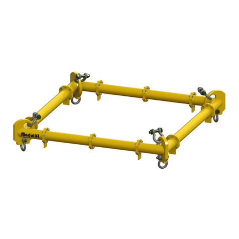
The Modulift Trunnion Spreader is modular in length. Every Trunnion spreader consists of two End Units and
intermediate struts that can be bolted into the assembly to achieve dierent spans. The Trunnion End Unit is
also compatible with existing Modulift struts. The TRUN MOD 600/1000 has an assembled span ranging from
8ft to 85ft in 1ft increments.
Strut
Trunnion
End Unit
α= Base to sling angle α
TRUN MOD 600/1000
Fig. 1 – Typical Spreader Assembly
User Instructions
Should you nd your equipment is no longer of use,
please dispose of in a responsible manner. Please
contact Modulift if you need further guidance
Table 2 – Load v Span
© Copyright 2015 Modulift.
All rights reserved.
Modulift UK Ltd tel: 011 44 1202 621511 email: [email protected] www.modulift.com
User Instructions
Do’s & Don’ts
● Do ensure to load the spreader through the main trunnion
pin only. i.e. adhere to Fig. 1.
● Do keep the loaded spreader clear of obstacles
– any contact could cause beam failure.
● Do ensure correct use of appropriate top slings, do not twist
any slings unnecessarily.
● Do not hang any load from the spreader tube or anges.
● Do not exceed stated SWL for that particular span
– adhere to Table 2.
● Do not rig the lower slings less than 45 degrees BSA.
● When moving or positioning long struts or assemblies use
tag lines to control movement.
● Individual components can be heavy and extreme care must
be taken if manual handling.
Recommended top sling types:
Textile slings, cable laid wire rope slings or grommets.
Slings must have soft eyes. Always ensure clearance between
the sling and end unit.
Note: Lengthening the slings can give greater clearance.
Refer to Modulift supplier if in doubt.
Assembly Procedure
Please refer to separate assembly and setup
procedure for more information.
WARNING!
TRUN MOD 600/1000 US SEP 2015
● The rigger must ensure that there is a clearance between
the sling end tting and the end unit as shown above.
● Max number of struts allowed in spreader assembly: 6.
● Assemble longer struts in the centre of the spreader
conguration.
● Sling angle is crucial to safe use of spreader.
Span
(ft)
Base to Sling
Angle (BSA) αRecommended Conguration
EU - End Unit (4ft)
To calculate the SWL at intermediate spans utilising
the 1ft strut, round up the span to the next
longest span inTable 2, and use the stated SWL.
60°
SWL
metric tons
(tonnes)
Min.top
sling
length
(ft in)
81000 8 EU EU
10 1000 10 EU 2 EU
12 1000 12 EU 4 EU
14 1000 14 EU 4 2 EU
16 1000 16 EU 4 4 EU
18 1000 18 EU 5 5 EU
20 1000 20 EU 4 4 4 EU
22 1000 22 EU 10 4 EU
24 1000 24 EU 10 4 2 EU
26 1000 26 EU 10 4 4 EU
28 1000 28 EU 10 5 5 EU
30 1000 30 EU 10 10 2 EU
32 1000 32 EU 10 10 4 EU
34 1000 34 EU 20 3 3 EU
36 1000 36 EU 20 4 4 EU
38 1000 38 EU 20 5 5 EU
40 1000 40 EU 20 10 2 EU
42 1000 42 EU 20 10 4 EU
44 1000 44 EU 20 10 4 2 EU
46 1000 46 EU 20 10 4 4 EU
48 1000 48 EU 20 10 10 EU
50 1000 50 EU 20 10 10 2 EU
52 986 52 EU 20 10 10 4 EU
54 939 54 EU 20 20 4 2 EU
56 891 56 EU 20 20 4 4 EU
58 842 58 EU 20 20 10 EU
60 801 60 EU 20 20 10 2 EU
62 755 62 EU 20 20 10 4 EU
64 713 64 EU 20 20 10 4 2 EU
66 673 66 EU 20 20 10 4 4 EU
68 632 68 EU 20 20 20 EU
70 604 70 EU 20 20 20 2 EU
72 567 72 EU 20 20 20 4 EU
74 534 74 EU 20 20 20 4 2 EU
76 502 76 EU 20 20 20 4 4 EU
78 470 78 EU 20 20 20 10 EU
80 444 80 EU 20 20 20 10 2 EU
82 415 82 EU 20 20 20 10 4 EU
84 390 84 EU 20 20 20 10 4 2 EU
85 378 85 EU 20 20 20 10 4 3 EU
Clearance
TRUN MOD 600/1000
Assembly and setup
Modulift UK Ltd tel: +44(0)1202 621511 email: [email protected] www.modulift.com
© Copyright 2015 Modulift. All rights reserved.
TRUN MOD
Assembly TRUN MOD UK OCT 2015
1. Firstly lay out the 4 top slings and connect them
all to the crane hook.
3. Ensure that the sling eyes for the top slings are
pushed in tight to the side cheeks of the beam, this
will leave room for the bottom sling eyes.
5. The bottom slings which are furthest away
from the spreader will need to be pulled across
the other pair of slings to help the eyes line up
with the trunnion.
7. When disassembling the beam, the lower slings
should be pulled inwards parallel to the spreader,
this will ensure that the eyes can be removed easily.
2. Then slew to one end of the beam and connect
a pair of slings, before repeating the process at the
other end.
4. Lay out the bottom slings and then lift the
spreader and put it down in the middle with a pair
of slings each side.
6. Do not forget to connect the safety chains on
both end units before lifting the beam out of reach.
8. Ensure that the Do’s and Don’ts of the user
instructions are followed to ensure a safe lift.

Other Modulift Lifting System manuals

Modulift CMOD 50 User manual

Modulift

Modulift CMOD 50 User manual

Modulift MOD 24 User manual

Modulift

Modulift MOD 24 User manual

Modulift MOD 50 User manual

Modulift

Modulift MOD 50 User manual

Modulift TRUN MOD 250 User manual

Modulift

Modulift TRUN MOD 250 User manual

Modulift CMOD 6 User manual

Modulift

Modulift CMOD 6 User manual

Modulift MOD 12 User manual

Modulift

Modulift MOD 12 User manual

Modulift MOD 6 User manual

Modulift

Modulift MOD 6 User manual

Popular Lifting System manuals by other brands

Lift Products Moto-Cart Jr Service manual

Lift Products

Lift Products Moto-Cart Jr Service manual

MoJack HDL 45501 Instructions for assembly and operation

MoJack

MoJack HDL 45501 Instructions for assembly and operation

ReadyLift 46-5780 manual

ReadyLift

ReadyLift 46-5780 manual

Genie Z-80/60 Operator's manual

Genie

Genie Z-80/60 Operator's manual

Zepro ZHD-1500-MA-DA Installation instruction

Zepro

Zepro ZHD-1500-MA-DA Installation instruction

Sealey AK98941 instructions

Sealey

Sealey AK98941 instructions

morse Kontrol-Karrier 185A Operator's manual

morse

morse Kontrol-Karrier 185A Operator's manual

TERRY Melody 2 hydraulic MK2 installation manual

TERRY

TERRY Melody 2 hydraulic MK2 installation manual

TRIUMPH BOARD LiftBox manual

TRIUMPH BOARD

TRIUMPH BOARD LiftBox manual

Ricoh PF4000 Series quick start guide

Ricoh

Ricoh PF4000 Series quick start guide

Ravaglioli KPX341 Translation of the original instructions

Ravaglioli

Ravaglioli KPX341 Translation of the original instructions

Parkside 338547 2001 operating instructions

Parkside

Parkside 338547 2001 operating instructions

Pro-Lift T2151 owner's manual

Pro-Lift

Pro-Lift T2151 owner's manual

Snorkel TL37J parts manual

Snorkel

Snorkel TL37J parts manual

Braun Vista 2 NVL Series Service manual

Braun

Braun Vista 2 NVL Series Service manual

morse 86 Operator's manual

morse

morse 86 Operator's manual

Atlas PV-10P Installation & operation manua

Atlas

Atlas PV-10P Installation & operation manua

WERTHER INTERNATIONAL 209I/B Instruction and maintenance manual

WERTHER INTERNATIONAL

WERTHER INTERNATIONAL 209I/B Instruction and maintenance manual

manuals.online logo
manuals.online logoBrands
  • About & Mission
  • Contact us
  • Privacy Policy
  • Terms and Conditions

Copyright 2025 Manuals.Online. All Rights Reserved.