3M Speedglas 9002 Installation instructions

User Instruction
Bedienungsanleitung
Notice d’instructions
Èíñòðóêöèÿ ïî ýêñïëóàòàöèè
²íñòðóêö³ÿ ç åêñïëóàòàö³¿
Instruzioni d’uso
Gebruiksaanwijzing
Instrucciones de uso
Instruções de uso
Bruksanvisning
Bruksanvisning
Brugsanvisning
Käyttöohjeet
Kasutusjuhend
Vartotojo žinynas
Lietošanas instrukcija
Instrukcja obs³ugi
Uživatelská pøíruèka
Használati utasítás
Instrucţiuni
Navodila za uporabo
Užívatel’ská príruèka
Upute za uporabu
Èíñòðóêöèè çà èçïîëçâàíå
Kullanýcý Talimatlarý
Oäçãßåò XñÞóçò
KKvvttyyrrhhttkkssmmbbwwvvmmyywwttvvaarrvvhh
3M
™
SPEEDGLAS
™
9002


Parts List
40 11 90
40 18 90
40 11 95
40 18 95
16 60 00
16 50 10
42 20 00
17 10 20-23
42 80 00
42 80 10
42 80 20
42 80 30
42 80 40
42 80 50
43 20 00
43 10 00
42 60 00
42 70 00
42 70 71
16 75 20
16 75 25
16 80 00
16 80 10
16 50 20
16 40 09
16 40 05
43 20 15
16 91 00 16 90 01


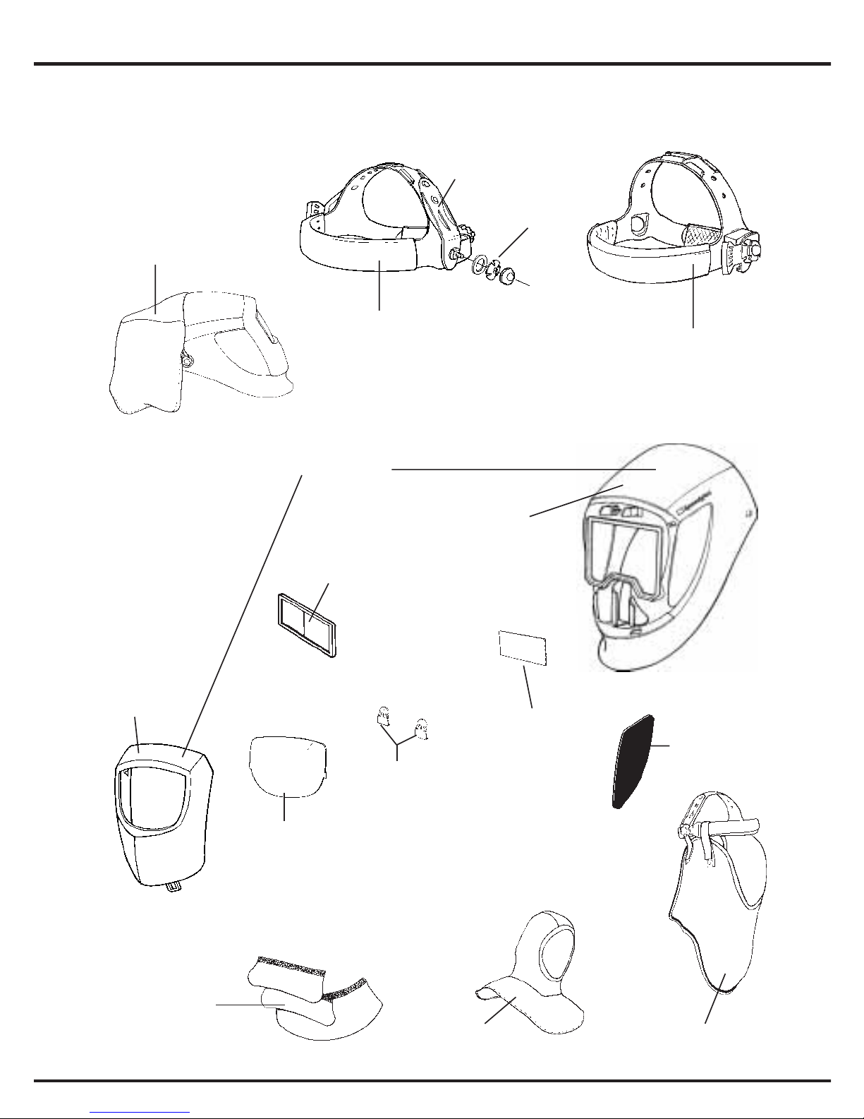
User manual 3MTM SpeedglasTM 9002
0196
Notified body 0196 DIN CERTCO
Prüf- und Zertifizierungszentrum Aalen
Augenschutz und Persönliche Schutzausrüstung
Gartenstraße 133, 73430 Aalen, Germany
1ïUser Instruction . . . . . . . . . . . . . . . . . . . . . . . page 5-14
3Bedienungsanleitung . . . . . . . . . . . . . . . . . . . . . . . Seite 15-24
2Notice d’instructions . . . . . . . . . . . . . . . . . . . . . . . page 25-33
rÈíñòðóêöèÿ ïî ýêñïëóàòàöèè
. . . . . . . . . . . .
ñòðàíèöà 34-42
u²íñòðóêö³ÿ ç åêñïëóàòàö³¿
. . . . . . . . . . . . . . . . .
ñòîð³íêà 43-51
4Instruzioni d’uso . . . . . . . . . . . . . . . . . . . . . . . . . Pagina 52-60
6Gebruiksaanwijzing . . . . . . . . . . . . . . . . . . . . . . pagina 61-69
5Instrucciones de uso . . . . . . . . . . . . . . . . . . . . . página 70-78
-Instruções de uso . . . . . . . . . . . . . . . . . . . . . . . . página 79-87
9Bruksanvisning . . . . . . . . . . . . . . . . . . . . . . . . . . . . side 88-95
7Bruksanvisning . . . . . . . . . . . . . . . . . . . . . . . . . . . . Sida 96-104
8Brugsanvisning . . . . . . . . . . . . . . . . . . . . . . . . . . . . side 105-113
0Käyttöohjeet . . . . . . . . . . . . . . . . . . . . . . . . . . . . . . . sivu 114-121
éKasutusjuhend . . . . . . . . . . . . . . . . . . . . . . . . . . . . . . lk. 122-130
|Vartotojo žinynas . . . . . . . . . . . . . . . . . . . . . . . puslapis 131-138
lLietošanas instrukcija . . . . . . . . . . . . . . . . . . . lappuse 139-147
HInstrukcja obs³ugi . . . . . . . . . . . . . . . . . . . . . . . . strona 148-157
FUživatelská pøíruèka . . . . . . . . . . . . . . . . . . . . . . strana 158-166
JHasználati utasítás . . . . . . . . . . . . . . . . . . . . . . . . . oldal 167-175
LInstrucţiuni . . . . . . . . . . . . . . . . . . . . . . . . . . . . . paginæ 176-184
SNavodila za uporabo . . . . . . . . . . . . . . . . . . . . . . . stran 185-192
DUžívatel’ská príruèka . . . . . . . . . . . . . . . . . . . . . . strana 193-201
AUpute za uporabu . . . . . . . . . . . . . . . . . . . . . . . . . strana 202-210
KÈíñòðóêöèè çà èçïîëçâàíå . . . . . . . . . . . . . . . . . . ñòð. 211-219
:Kullanýcý Talimatlarý . . . . . . . . . . . . . . . . . . . . . . . . Sayfa 220-227
=Oäçãßåò ×ñÞóçò . . . . . . . . . . . . . . . . . . . . . . . . . Óåëßäá 228-236
iKKvvttyyrrhhttkkssmmbbwwvvmmyywwttvvaarrvvhh. . . . . . . . . . . . . . . . . . . MMyyddvvmmii237-244

Instruction Speedglas 9002
BEFORE WELDING
For your own protection read these instructions carefully before
using Speedglas 9002.
Assemble the equipment according to the illustrations in this
manual. The complete equipment is illustrated in figure A:1
Adjust the welding shield according to your individual require-
ments. The headband should be adjusted both in diameter and
height. The angle between face and shield should also be adju-
sted and is recommended to be 10°-12° according to figure A:2
All Speedglas automatically darkening welding filters are desi-
gned to be used in arc welding or gas cutting applications. The
unit is suitable for all arc welding processes such as MIG, MAG,
TIG, MMA, Plasma Arc, and Air Carbon. The welding filter can
also be used for gas welding when the filter is in the “off” state,
shade 5-6.
The shade number in the dark state is marked on the product. The
suitable shade number should be chosen according to EN 379
(also available in EN 169).
Speedglas 9002 automatically darkening welding filter gives
permanent protection (shade13) against harmful UV- and IR-radia-
tion, regardless if the filter is in the light or dark state and also in
the event of battery or electronic failure.
The welding filter has two photo sensors that react independent-
ly as the welding arc is struck and causes the filter to darken. Two
lithium batteries (3V CR2032) are used as the power source.
Speedglas 9002X has an additional solar panel for extended bat-
tery lifetime. The welding filter is automatically switched off appro-
ximately 60 minutes after the last time the arc was struck.
6
1 ï

Note!
The Speedglas 9000 welding shield should always be used
together with original Speedglas spare parts such as inner and
outer protection plates, part numbers according to parts list.
The use of non Speedglas components might impair protection
and will void warranty claims and approvals.
Note!
Speedglas 9000 welding shields are not suitable for laser welding
or laser cutting. Speedglas 9000 welding shields are suitable
for all positions except heavy duty overhead cutting/welding
operation due to the risk of molten metal.
Markings
The welding filter is marked with the shade range.
The eye and face protection classification is made according to
EN 379, EN 166, EN 169 and EN 175.
The following is an example (EN 379):
Note! The above is an example. Valid classification is marked on
each product.
On the welding shield and the outer protection plate, marking can
be found that indicates safety class for protection against high
7
1ï
Light shade
3 / 9-13 3M 1 / 1 / 1 / 2 / EN379 CE
Dark shade(s)
Manufacturer identification
Optical class
Diffusion of light class
Variations in Luminous transmittance class
Angle dependency class (optional marking)
Certification mark or number of standard

speed particles. F stands for low energy impact and B stands for
medium energy impact. If the protection meets the requirements
at extremes of temperature (-5°C to +55°C) the marking is
completed with the letter T.
Additional markings on the product refer to other standards.
Storage
The equipment should be stored in a clean and dry environment,
temperature range -30°C to + 70°C and relative humidity less
than 90 % RH.
FUNCTIONS
On/Off (Figure B)
To activate the welding filter, press the ON button. After each short
press of the ON button, the current settings (shade, sensitivity and
delay) are displayed by flashing LED’s. The welding filter is swit-
ched off approximately 60 minutes after welding has been com-
pleted. The welding filter can also be switched off manually by
pressing the ON button for a few seconds.
Selection of Shade Number setting
In order to see which Shade Number the welding filter is current-
ly set to, momentarily press the Shade button. To reselect ano-
ther Shade Number, press the Shade button again while the LED
is flashing, and then keep pressing the button to increment the
flashing LED to the correct Shade Number.
Speedglas 9002V, 9002X
Five different Shade Number settings are available in the dark
state, 9, 10, 11, 12 and 13.
Speedglas 9002D
Two different Shade Number settings are available in the dark
state, 9 and 11.
8
1 ï

Setting of detector Sensitivity function
Setting the performance of the photo detector system (which res-
ponds to the light from the welding arc) is made with the Sensitivi-
ty button. In order to see which position the welding filter is current-
ly set to, momentarily press the Sensitivity button. To select ano-
ther setting, press the Sensitivity button again while the LED is flas-
hing, and continue to press until the LED shows the desired setting
.
Speedglas 9002V, 9002X
Position 1 Least sensitive setting. Used if there is disturbing light
from other welders in the vicinity.
Position 2 Normal position. Used for most types of welding
indoors and outdoors.
Position 3 Position for welding with low current or where the
welding arc becomes stable. (eg TIG welding at low
amps)
Position 4 Extreme photo detector sensitivity. Suitable for very
low current welding or pipe welding where part of the
arc is obscured from view.
Speedglas 9002D
Position - Normal position. Used for most types of welding indo-
ors and outdoors.
Position + Position for welding with low current or where the
welding arc becomes stable. (eg TIG welding at low
amps)
Finding the right setting of detector
Speedglas 9002V, 9002X
In order to find a suitable sensitivity setting for the detector, start
with the setting, before welding, in Position 2. This is a normal
position that functions in the majority of situations. If the filter does
not darken during welding as desired, raise the sensitivity to Posi-
tion 3 or 4 until a definite shift to dark position takes place. Should
9
1ï

a too high sensitivity be selected, it is possible that the filter
remains in the dark position after welding is complete due to sur-
rounding light. Should this arise, make an adjustment to a less
sensitive setting where the welding filter both darkens or lightens
as desired. If the welding filter functions well in Position 2, but dar-
kens due to another welding process being in progress in the vici-
nity, select Position 1.
Speedglas 9002D
In order to find a suitable sensitivity setting for the detector, start
with the setting, before welding, in – position. This is a normal
position that functions in the majority of situations. If the filter does
not darken during welding as desired, raise the sensitivity to
+position.
Setting of the Delay to the light state
(Speedglas 9002V/9002X)
The Delay setting controls how fast the filter returns to the light
state after welding has finished. In order to see which position it
is currently set to, momentarily press the Delay button. To select
another setting, press the Delay button again while the LED is
flashing, and continue to press until the LED increments to the
desired setting.
Position - This position causes the filter to return to the light
state very rapidly and is used for example in spot or
tack welding where the welder needs to have a clear
view quickly after finishing the weld.
Position I Normal position.
Position + This position extends the delay time almost doubling
it over the normal setting and is for use in situations
where the weld pool is extremely bright after finishing
the weld.
10
1 ï

Low battery indicator
The “low battery” indicator flashes repeatedly when the battery
should be replaced.
Note! The welding filter will not go to dark position in applications
where there is no welding light at all visible for the photo detector
system.
Note! Other light sources with fast flashing light eg warning lights
can make the photo detector react and make the filter
darkens/lightens with the same frequency as the flashing light
source.
MAINTENANCE
Replacement of outer protection plate.
Remove silver front cover. (Figure C:1 - C:2) Remove the used
outer protection plate. Make sure that any protective films are
removed from the outer protection plate and place the new outer
protection plate within the front recess of the welding filter as indi-
cated in figure C:3. Place the silver front cover back into position
by locating the bottom pegs in the holes, position one of the upper
corners and snap in the second upper corner. (Figure C:4 - C:6)
Note! Silver front cover must always be used.
Replacement of inner protection plate.
The used inner protection plate is removed as illustrated on figu-
re D:1. The new inner protection plate should be inserted after the
protective film is removed.
Locate one of the sides by fixing the corners according to figure
D:2. Bend the middle part and fix the other two corners.
11
1ï

12
1 ï
Replacement of welding filter.
The welding filter can be removed and replaced according to figu-
re E:1 - E:3 and C:4 - C:6.
Replacement of battery.
The battery should be replaced when the welding filter does not
become light when switched ON. The welding filter must be remo-
ved before battery replacement can be carried out. Take out the
two battery holders (a small screwdriver could be used if neces-
sary). Remove the used batteries and dispose of them according
to the local regulations.
Insert new batteries in the battery holder according to figure F. Push
the battery holders into the welding filter until they snap in position.
Temperature range
The recommended operating temperature range for the welding
filter is -5°C to +55°C. The welding filter should be stored in a
clean and dry environment, temperature range -30°C to +70°C.
Inspection
Carefully inspect Speedglas Automatically Darkening Welding Fil-
ter regularly. Cracked, pitted or scratched filter glass or protection
plates reduce vision and seriously impair protection. These should
be replaced immediately to avoid damage to the eyes. Inspect the
complete Speedglas system frequently and replace worn or dama-
ged parts. The sensors on the welding filter must be kept clean and
uncovered at all times to provide correct functioning.
Note! To inspect the battery function, electronic function and
buttons, press the buttons and the LED´s will flash.
Cleaning
Clean the shield with mild soap and lukewarm water. Do not use
solvents. Clean the welding filter with a clean lint-free tissue or
cloth. Do not immerse in water.
Do not use solvents.

13
1ï
Caution!
Use this welding shield ONLY for face and eye protection against
harmful rays, sparks and spatter from welding and cutting. The
protection plates are strong but not unbreakable. This shield will
not protect against severe impact hazards, such as fragmenting
grinding wheels or abrasive discs, explosive devices or corrosive
liquids. Machine guards or eye splash protection must be used
when these hazards are present, or as specified by local regula-
tions.
The Welding Shield is heat resistant and approved against stan-
dard requirements for flammability but can catch fire or melt in
contact with open flame or very hot surfaces. Keep the helmet
clean to minimise this risk.
The manufacturer is not responsible for any modifications to the
welding filter or fittings into other welding shields than Speedglas
9000 welding shields.
Protection can be seriously impaired if unapproved modifications
are made.
Persons who suffer from allergic skin reactions should make the
correct choice of headband material before using the product.
Wearers of ophthalmic spectacles should be aware that in the
case of severe impact hazards the deformation of the shield might
cause the inside of the shield to come into contact with the spec-
tacles creating a hazard for the wearer.
In all welding processes the arc should only be viewed with the
correct dark shade.

Parts List
part no description
16 40 05 Ear and throat protection
in leather (3 parts)
16 40 09 Head protection in TecaWeld
16 50 10 Headband with mounting
details
16 50 20 Headband 1 UL with
mounting details
16 60 00 Mounting details for
headband
Sweatband
16 75 20 - in towelling, purple, 2 pcs.
16 75 25 - in micro fiber, black, 2 pcs.
16 80 00 - in leather, 1 pc.
16 80 10 - in fleece, brown, 2 pcs.
16 90 01
Throat protection in TecaWeld
16 91 00 Welding hood in TecaWeld
17 10 20 Magnifying lens 1,0
17 10 21 Magnifying lens 1,5
17 10 22 Magnifying lens 2,0
17 10 23 Magnifying lens 2,5
Speedglas 9000
welding shield
(excl. headband)
40 11 90 - without SideWindows
40 18 90 - with SideWindows
40 11 95 Inner welding shield
without SideWidows
40 18 95 Inner welding shield with
SideWindows
part no description
42 20 00 Battery pkg of 2
Outside protection plate,
pkg of 10
42 60 00 - standard
Plate marking 42 01 50
42 70 00 - scratch resistant
Plate marking 42 01 00
42 70 71 - heat resistant
Plate marking 42 01 70
42 80 00 Inside protection plate
Speedglas 9002V/9002D
pkg of 5
Plate marking 42 02 00
42 80 10 Inside protection plate
Speedglas 9002X pkg of 5
Plate marking 42 02 10
Inside protection plate
+1 Shade number
42 80 20 - Speedglas
9002V/9002D
,
5 pcs.
42 80 30 -
Speedglas 9002X, 5 pcs.
Inside protection plate
+2 Shade number
42 80 40 - Speedglas
9002V/9002D
,
5 pcs.
42 80 50 -
Speedglas 9002X, 5 pcs.
43 10 00 Battery cover pkg of 2
43 20 00 Silver front cover
43 20 15* SideWindows cover
plate 5 pairs
* 40 18 95 should be ordered for new
SideWindows
14
1 ï

Bedienungsanleitung Speedglas 9002
VOR INBETRIEBNAHME!
Lesen Sie diese Hinweise zu Ihrer eigenen Sicherheit sorgfältig,
bevor Sie Speedglas 9002 benutzen.
Bauen Sie die Einzelteile wie in den Abbildungen beschrieben
zusammen. Eine Artikelübersicht ist in Abbildung A:1 dargestellt.
Stellen Sie sicher, dass die innere und äußere Vorsatzscheibe
korrekt eingesetzt sind. Das Kopfband sollte sowohl im Durch-
messer als auch in der Höhe individuell eingestellt werden. Der
Winkel zwischen Gesicht und Schweißmaske sollte 10-12 Grad
betragen (siehe Abbildung A:2).
Alle Speedglas Automatik-Schweißfilter sind zum Gebrauch bei
Lichtbogenschweißen oder Gasschneiden geeignet. Das Produkt
schützt wirkungsvoll bei allen Lichtbogenschweißprozessen wie
MIG, MAG, WIG (TIG), Elektrodenschweißen und Plasma-
schneiden. Zusätzlich kann man das Produkt zum Gasschweißen
verwenden. In diesem Falle sollte die Elektronik ausgeschaltet
sein. Als Sichtschutz ergibt sich die Schutzstufe 5-6.
Jedes Produkt ist mit der Schutzstufe gekennzeichnet. Die Auswahl
der passenden Schutzstufe sollte entsprechend der Norm EN379
(auch EN169) vorgenommen werden. Speedglas 9002 Automa-
tikschweißfilter geben permanenten Schutz (Stufe 13) gegen
schädliche UV-und IR-Strahlung. Unabhängig davon ob der Filter
in der Hell-oder Dunkelstufe eingestellt ist, oder ob Batterie- bzw.
Elektronikfehler vorliegen.
D
er Schweißfilter ist mit zwei Photosensoren ausgerüstet, welche
unabhängig voneinander reagieren und zur Verdunkelung führen,
sobald der Lichtbogen gezündet ist. Zwei auswechselbare Lithi-
umbatterien (3V-CR 2032) dienen als Energiequelle.
Speedglas 9002X hat zusätzlich Solarzellen, welche die Batterie-
lebensdauer deutlich erhöhen.
Ca. 60 Minuten, nachdem der letzte Lichtbogen gezündet wurde,
schaltet die Elektronik automatisch ab. Eine manuelle Abschal-
3
15

tung erreicht man durch ein etwa 4 Sekunden andauerndes
Drücken des Einschaltknopfes.
Achtung !
Die Speedglas 9000 Schweißschutzmasken müssen immer mit
Original-Speedglas-Ersatzteilen, wie inneren und äußeren Vor-
satzscheiben benutzt werden.
Die Artikelnummern finden Sie in unserer Artikelliste.
Der Einsatz von Nicht-Speedglas Originalteilen kann die Schutz-
wirkung beeinträchtigen und führt zum Verlust von Gewähr-
leistungsansprüchen!
Achtung !
Speedglas 9000 Schweißermasken sind für alle Schweißpositio-
nen einsetzbar. Während einer Überkopf-Schweißposition ist
jedoch darauf zu achten, dass sich kein geschmolzenes Metall
auf der Schweißmaske ablagert.
Speedglas 9000 Schweißmasken sind geeignet für die meisten
Schweißverfahren. Sie sind nicht geeignet für Laserschweißen
und Laserschneiden.
Kennzeichnung
Der Schweißschutzfilter ist gekennzeichnet mit den entsprechen-
den Schutzstufen.
Die Schutzklasse für Augen-und Gesichtsschutz entspricht der
EN 379, EN 166, EN 169 und EN 175.
Es folgt ein Beispiel (EN379):
3
16
Hellstufe
3 / 9-13 3M 1 / 1 / 1 / 2 / EN379 CE
Dunkelstufe(n)
Kennbuchstabe des Herstellers
Optische Klasse
Streulichtklasse
Homogenitätsklasse
Klasse der Winkeleigenschaften
(optionale Kennzeichnung)
Zertifizierungskennzeichen oder Nr des Standards

Achtung ! Bei den Ausführungen handelt es sich um ein Beispiel.
Die gültige Kennzeichnung befindet sich auf dem Produkt.
Das Schweißerkopfteil und die äußere Vorsatzscheibe sind mit
Kennbuchstaben gekennzeichnet, welche die Schutzklasse
gegen Stoßenergie (umherfliegende Teile) angeben.
F steht für niedrige Stoßenergie und B steht für mittlere Stoß-
energie. Wenn zusätzlich die Schutzausrüstung die Anforderun-
gen an extreme Temperaturen (-5°C bis +55°C) erfüllt, ist sie
außerdem mit dem Buchstaben T gekennzeichnet.
Davon abweichende Kennzeichnungen beziehen sich auf ande-
re Sicherheitsstandards.
Lagerung
Die Schutzausrüstung sollte in sauberer und trockener Umge-
bung in einem Temperaturbereich von -30°C bis +70°C gelagert
werden. Die relative Luftfeuchtigkeit in der Umgebung sollte maxi-
mal 90% betragen.
FUNKTION
Ein/Aus (Abb. B)
Zum Einschalten des Schweißfilters die Taste ON drücken. Durch
mehrmaliges kurzes Drücken der Taste ON werden die verschie-
denen Einstellungsparameter angezeigt (die Lampen bei den ent-
sprechenden Tasten blinken). Der Schweißfilter schaltet sich ca.
60 Minuten nach Beendigung des Schweißeinsatzes automatisch
aus. Zum manuellen Ausschalten des Schweißfilters die Taste
ON mehrere Sekunden lang gedrückt halten.
Auswahl der Schutzstufe
Fünf verschiedene Schutzstufen sind verfügbar: 9, 10, 11, 12 und
13. Zum Feststellen der aktuellen Verdunkelungsintensität die
Taste Shade drücken. Zum Ändern der Schutzstufeneinstellung
noch einmal die Taste Shade drücken, solange die Leuchte blinkt.
Anschließend die Taste mehrmals drücken, bis der gewünschte
Wert eingestellt ist.
3
17

Speedglas 9002V, 9002X
Fünf verschiedene Schutzstufen sind verfügbar: 9, 10, 11, 12
und 13.
Speedglas 9002D
Zwei verschiedene Schutzstufen sind einstellbar. Stufe 9 und 11.
Einstellung der Empfindlichkeit
Die Einstellung der Detektorempfindlichkeit (Umschalten der Filter
auf Verdunkelung) erfolgt über die Taste Sensitivity. Zum Fest-
stellen der aktuellen Einstellung die Taste Sensitivity drücken.
Zum Ändern der Einstellung noch einmal die Taste Sensitivity
drücken, solange die Leuchte blinkt. Anschließend die Taste mehr-
mals drücken, bis der gewünschte Wert eingestellt ist.
Speedglas 9002V, 9002X
Position 1 Etwas unempfindlicher als Normalstellung. Bei stör-
enden Lichteinflüssen, z.B. von einem Schweißer in
unmittelbarer Nähe.
Position 2 Normalstellung. Für die weitaus meisten Schweiß-
Arbeiten in Innenräumen sowie im Freien.
Position 3 Stellung für Niedrigampere-Schweißen. Für Ein-
sätze, bei denen geringe Stromstärken und/oder ein
hochgetakteter Lichtbogen vorliegt (z.B. WIG-
Schweißen).
Position 4 Stellung mit hoher Detektorempfindlichkeit. Für
Einsätze mit extrem geringen Stromstärken, wenn
der Detektor in keiner anderen Stellung anspricht.
Speedglas 9002D
Position - Normalstellung. Für die weitaus meisten Schweiß-
Arbeiten in Innenräumen sowie im Freien.
Position + Stellung für Niedrigampere-Schweißen. Für Ein-
sätze bei denen geringe Stromstärken und /oder
ein hochgetakteter Lichtbogen vorliegt. (z.B.WIG-
Schweißen)
3
18

Die Wahl der richtigen Empfindlichkeitseinstellung
Speedglas 9002V, 9002X
Zur Ermittlung der adäquaten Empfindlichkeit den Detektor
zunächst in die Position 2 bringen. Es handelt sich um die Nor-
malstellung, die für die allermeisten Schweißeinsätze passend
ist. Wird der Verdunkelungsmechanismus nicht wie gewünscht
ausgelöst, die Empfindlichkeit erhöhen (Position 3 oder 4), bis
eine sichere Verdunkelung gewährleistet ist. Bei einer höheren
Detektoreinstellung kann es vorkommen, dass die Verdunkelung
auch nach Abschließen des Schweißvorgangs aufgrund einer
anderen Lichtquelle aufrecht erhalten bleibt.
In diesem Fall auf eine niedrigere Stufe schalten, so dass sowohl
die Verdunkelung als auch die Aufhebung derselben zufrieden-
stellend funktioniert.
Spricht der Schweißfilter in Position 2 gut an, wird die Verdunke-
lung jedoch auch von einer anderen Lichtquelle in der Nähe aus-
gelöst, die Position 1 wählen.
Speedglas 9002D
Vor Beginn des Schweißvorganges stellen Sie die Empfindlich-
keitanzeige in die Position -.
Dies ist die Standardeinstellung und für die meisten Schweißan-
wendungen geeignet. Wenn der Schweißfilter während des
Schweißens jedoch nicht abdunkelt, stellen Sie den Empfindlich-
keitsregler in die + Position.
Einstellung der Aufhellungsverzögerung
(Speedglas 9002V/9002X)
Mit der Einstellung der Aufhellungsverzögerung kann die
Geschwindigkeit vorgewählt werden, mit der der Schweißfilter
nach Beendigung des Schweißvorganges aus der dunklen
Schutzstufe wieder in die Hellstufe zurückschaltet. Um festzu-
stellen, welche Einstellung vorliegt, muss der Bedienschalter
einmal kurz betätigt werden. Damit diese Einstellung verändert
werden kann, muss (während die LED – Leuchte noch blinkt) –
3
19

der Bedienschalter solange erneut betätigt werden, bis die
gewünschte Einstellung erreicht ist.
Position-
Diese Einstellung wählen, wenn der Schweißfilter
in der Normalstellung nach Erlöschen des Licht-
bogens zu lange verdunkelt (z.B. beim Punkt-
schweißen oder bei anderen Schweißarbeiten,
bei denen eine rasche Aufhellung erforderlich ist).
Position I Normalstellung
Position + Diese Stellung wählen, wenn der Schweißfilter in
der Normalstellung zu früh aufhellt (z.B. bei
hohen Amperestärken, um Blendungen durch
Schmelzgut zu vermeiden).
Batterieanzeige (Low bat)
Die Batterieanzeige (Low bat) blinkt, wenn ein Batterieaustausch
erforderlich ist.
Achtung ! Der Schweißschutzfilter verdunkelt nicht, wenn die
Photosensoren keinen Kontakt zum Lichterbogen haben.
Achtung ! Andere Lichtquellen mit hoher Lichtfrequenz können
ebenfalls zum Verdunkeln des Schweißfilters führen. (z.B.Warn-
leuchten)
WARTUNG
Austausch der äußeren Vorsatzscheibe (Abbildung C:1-C:6)
Nehmen Sie das silberfarbene Hitzeschutzschild ab (siehe Abbil-
dung C:1-C:2). Entfernen Sie die gebrauchte Vorsatzscheibe.
Ziehen Sie den Schutzfilm von beiden Seiten der neuen Vorsatz-
scheibe ab und setzen Sie diese in den Rahmen des Schweißfil-
ters, wie in Abbildung C:3 beschrieben.
Setzen Sie das Hitzeschutzschild wieder in das Kopfteil ein,
indem sie die beiden Haken in die unten dafür vorgesehenen
Löcher im Kopfteil stecken und eine Seite des oberen Randes des
3
20
Other manuals for Speedglas 9002
1
Table of contents
Languages:
Other 3M Welding System manuals
Popular Welding System manuals by other brands

DINSEO
DINSEO DIX TIG GO 1406.M HF Operation manual

Lincoln Electric
Lincoln Electric POWERTEC 305C PRO Operator's manual

Lincoln Electric
Lincoln Electric POWER WAVE R350 Operator's manual

Miller Electric
Miller Electric 057 607 owner's manual

Craftsman
Craftsman 196.205680 owner's manual

Kemppi
Kemppi FastMig M Series quick guide