LORCH V Series User manual

Service Manual
V Series
909.0340.1-05

page 2
Document no. 909.0340.1-05
Issue date: 10.03.2021
Contents
Machine........................................................................... 3
Safety precautions........................................................... 4
Common Logic functions................................................. 5
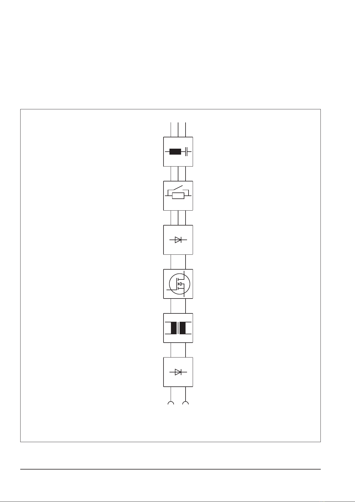
Inverter Principle.............................................................. 6
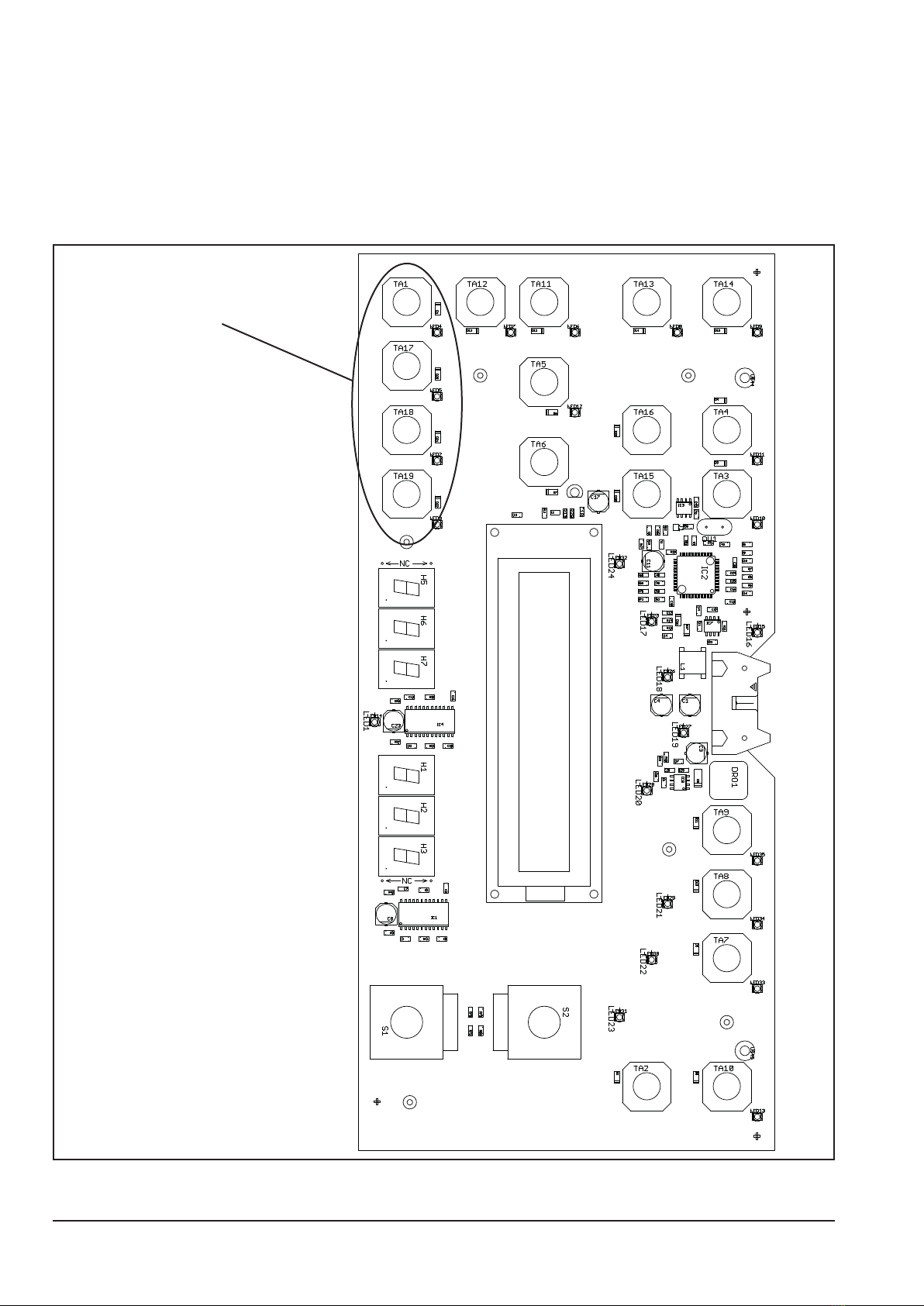
Pc-board DK-MAPRO...................................................... 7
Pc-board DK-DCI40 / DK-ACI40 ................................... 10
Pc-board DK-DCI45 / DK-ACI45 ....................................11
Pc-board DK-DCDRV .................................................... 13
Pc-board DK-ACDRV .................................................... 18
Pc-board DK-PWRUP ................................................... 20
Pc-board DP-S3NEFI .................................................... 21
Pc-board NEFI3x32....................................................... 22
Pc-board DK-GLCL3 ..................................................... 24
Pc-board DK-KSDC / DK-KSDCD / DK-KSDCN ........... 25
Pc-board DK-HFDC / DK-HFDC HV.............................. 27
Pc-board DK-UFI........................................................... 29
Pc-board DK-EMV......................................................... 29
Pc-board LSW ............................................................... 30
Current sensor VAC....................................................... 30
Control transformer........................................................ 31
Temperature monitoring................................................. 32
Supply voltages ............................................................. 33
Monitoring welding current ............................................ 34
Monitoring welding voltage............................................ 35
Cooling unit.................................................................... 36
Torch control.................................................................. 38
Remote control interface ............................................... 39
Monitoring primary current............................................. 40
Power-up cycle.............................................................. 41
Monitoring bus voltage .................................................. 42
Identication power units............................................... 43
Checking MOSFETs ...................................................... 44
Inside diagram diodes ................................................... 45
PE protection (optional)................................................. 45
List of error codes.......................................................... 46

page 3
Machine
Machine elements
1 torch 5 connector ground cable
2 front panel 6 connector external cooling unit
3 mains switch 7 mains cable
4 connections 8 gas hose
2
3
6
4
8
7
1
5
4
3
2
1

page 4
Safety precautions
Requirement
Use and maintenance of welding and cutting machines can be dangerous. Please draw user´s attention to
follow the safety precautions to avoid injuries. Welding and cutting machines must be used appropriately
and only by qualied/trained sta. Please follow safetyregulations and use safety precautions in order to
prevent accident when working with these machines.
Only qualied workers who are knowledgeabel and have been trained to work safely with test instruments and
equipment on energized circuits shall be permitted to perform testing work on electrical circuits or equipment were
there is danger of injury from accidental contact with energized parts or improper use of the test instruments and
equipment.
Use only original spare parts
Replace immediately any components that are not in perfect condition.
Norms
IEC 60974-4 In-service inspection and testing
Testing Lorch machines according to IEC 60974-4
- it is not necessary to disconnect any components of the power unit for the test
- it is recommended to disconnect the torch at water cooled machines
- the machine has to be cleaned properly before the test
- switch to MMA mode (stick electrode) if possible

page 5
Common Logic functions
component function cause
fan (power unit) on power modul temperature over 40°C
fan (power unit) o power modul temperature below 40°C
fan (cooling system) on after detection “arc established“
fan (cooling system) o after welding process, two minutes post-cooling time
pump on after detection “arc established“
pump o after welding process, two minutes post-cooling time
Pump test
- press the button “Acknowledge“ and the button gas test at the same time
- the pump is switched on for one minute
- the buttons “Acknowledge“ and gas test again to end the test manually
Reset settings
- press the button “Acknowledge“ and the button “TT Enter“ at the same time
- all parameters are reset to their factory settings
- doing the reset in Tiptronic mode, only the settings of the actual Job are reset
- all settings in Menu Extras remain unchanged
Master Reset
- press the button “Acknowledge“ and both arrow keys at the same time and keep them
presses for about 5 seconds
- the display shows “Master Reset“
- release all buttons
- all settings and parameters are reset to their factory settings
!!! CAUTION !!!
all Tiptronic jobs are deleted after a Master reset !!!

page 6
Inverter Principle
A welding inverter is a electronically controlled welding power source. At conventional transformer based ma-
chines, the mains voltage with 50/60 Hz is directly switched to the welding transformer. At a welding inverter the
mains voltage is rectied rst and with electronic power switches (MOSFETs or IGBTs) chopped into a frequency
of 80 kHz. This allows a very small construction of the welding transformer, because it‘s driven at this high fre-
quency. The basic structure of a welding inverter is always the same at Lorch power sources:
- mains rectier
- primary inverter
- transformer
- secondary rectier
mains
filter
3 phase mains
input
rectifier
primary
driver
transformer
secondary
rectifier
power
up

page 7
Pc-board DK-MAPRO
The pc-board DK-MAPRO is responsible for the welding sequence and is managing the process control of the
V-Series
(MAPRO = MAster-PROcess)
Functions
- Logicfunctions of the welding process
- generating and monitoring supply voltages
- driving powerup-relais
- driving power unit/units
- driving ignition device
- monitoring control and operating elements (DK-ACI40/DK-DCI40, remote control, torch buttons)
- driving solenoid valve
- driving fans
- driving waterpump
- monitoring owmeter
- monitoring mains- and output voltage
- generating signal „welding current on“
- managing communications between PC and machine
- managing and storage of all welding parameters
- CAN-bus
LEDs :
normal
LED state meaning
1 (green) ashing (half freq. of LED5) CPLD ok
2 (red) o Digital Signal Processor (DSP) ok
3 (green) on supply voltage 3.3V ok
4 (red) o Microcontroller ok
5 (green) ashing DSP is working
6 (green) ashing Microcontroller is working
malfunction
LED state meaning
1 (green) never on CPLD not working
2 (red) on DSP not working
3 (green) o supply voltage 3.3V missing : check 18V~ of control transformer X9/1 X9/2
4 (red) on Microcontroller not working
5 (green) never on DSP not working
6 (green) never on Microcontroller not working
If the LEDs are indicating a malfunction which can not be relieved by switching the machine o and
on again, it is recommended that the pc-board DK-MAPRO is exchanged.
DIP switch
The DIP switches 1-3 are needed for pro-
gramming the DSP (Process) via serial port.
The DIP switch 4 is set due to the type of
housing as V mobile or V driveable.
DIP switch ON OFF
1-3 serial program. mode normal operation
4cong. V mobile cong. V (driveable)
Overview fuses
fuse value [A] safeguarding
Si 6 1 fans (power unit)
Si 7 2,5 cooling unit (pump)
Si 11 1 cooling unit (fans)

page 8
Measuring points
designation measure point result
gas valve X1/1
X1/2
GND
+ +24V DC
supply from control transformer X6/1
X6/2
~
~
230V AC
supply voltage fan group 1 X7/1
X7/2
~
~
230V AC
supply voltage fan group 2 X25/1
X25/2
~
~
230V AC
supply voltage fan (cooling unit) X26/1
X26/2
~
~
230V AC
supply voltage pump (cooling unit) X8
X24
~
~
230V AC
supply from control transformer X9/1
X9/2
~
~
18V AC
supply voltage ow meter X12/1
X12/3
+
GND
+15V DC
supply voltage CAN interface X15/1
X15/2
GND
+ +15V DC
supply voltage CAN interface X16/1
X16/2
GND
+ +15V DC
supply voltage CAN interface X17/1
X17/2
GND
+ +15V DC
Overview connectors pc-board DK-MAPRO
connector designation
X1 connector gas valve
X2 connector to power unit 1 (primary)
X3 connector to power unit 2 (primary)
X4 connector to power unit 1 (secondary)
X5 connector to power unit 2 (secondary)
X6 230V supply fans/cooling unit (from control transformer)
X7 connector fan group 1 (power unit)
X8 connector pump (with X24)
X9 connector control transformer (supply voltage for pc-board)
X11 interface for HF ignition unit
X12 connector ow meter
X13 connector remote control socket
X14 connector torch buttons
X15 CAN interface
X16 CAN interface
X17 CAN interface
X18 connector front panel
X19 connector output voltage (to pc-board DP-EMV)
X20 connector serial interface (RS232: internal programming connector)
X21 JTAG-Interface (internal programming connector)
X22 JTAG-Interface (internal programming connector)
X23 connector fan 24V DC (only used in V mobile machines)
X24 connector pump (with X8)
X25 connector fan group 2 (power unit)
X26 connector fan (cooling unit)

page 9
Picture pc-board DK-MAPRO
X14
X13
X12
X11
X26
X8
X24
X25
X7
X6
X15
X16
X17
X18
X20
X19
X22
X21
X2
X3
X4
X5
X1
X23
X9
LED3
3,3V
DIP
S1
LED2 LED5
DSP
LED1
CPLD
LED6 LED4
Master
earth screw
measuring point
X9 control transformer

page 10
Pc-board DK-DCI40 / DK-ACI40
The pc-board DK-DCI40 (DC machines) and DK-ACI40 (AC machines) is the front panel with all buttons and opti-
cal displays.
Functions
- operating and handling of the machine
- display of operational parameters and error messages
Picture pc-board DK-DCI40 / DK-ACI40
buttons and LEDs only
mounted at pc-board
DK-ACI40
X1

page 11
Pc-board DK-DCI45 / DK-ACI45
The pc-board DK-DCI45 and DK-ACI45 are the front panels with all buttons and optical displays of the V mobile
machines.
Functions
- operating and handling of the machine
- display of operational parameters and error messages
Picture pc-board DK-DCI45 / DK-ACI45
X1

page 12
Function test of the front panel
The front panel has an internal function test. With this test, all LEDs and encoders can be checked. Switch be-
tween the single test forth and back with the arrow keys at any time.
Start test:
- press arrow key “left“ and “right“ (TA15 and TA16) at the same time
- the actual operating system version of the display is shown, e.g. : D 3 030204 (11)
- press right arrow key
- all LEDs are ashing and the LCD is toggeling between bright and dark
- press right arrow key
- the red LED at the key “electrode diameter“ is on
- press right arrow key
- all keys are tested, the key to be checked is indicated with a lit LED
- press right arrow key
- move the cursor (in LCD) with the encoder to the right and back to the left
- the display shows < End of tests... > and after 5 seconds the machine switches back to the normal display
before the test was executed

page 13
Pc-board DK-DCDRV
The pc-board DK-DCDRV is managing the primary drive level of the power unit.
Functions
- encoding power unit
- connection of the thermal sensor (at heat sink)
- supply current sensor
- monitoring bus voltage and supply voltage
- safety shut-down of power unit
- passthrough signal power-up relay
- passthrough output of current sensor
Encoding power unit
The type of the power unit is set via the DIP switch.
DIP 1 DIP 2 setting type
OFF OFF 240 A V24, V40
OFF ON 270 A V27
ON OFF 300 A V30, V50
ON ON reserviert
LED displays
normal
LED state designation
1 (red) o primary overcurrent shut down
2 (green) on drive level of low-side is ok
4 (green) on bus voltage max is ok
5 (green) on drive level of high-side is ok
6 (green) on bus voltage min is ok
malfunction
LED state reason
1 (red) on primary current is too high, power unit has been switched o
2 (green) never on no drive level low-side
4 (green) o bus voltage is too high (e.g. mains overvoltage)
5 (green) never on no drive level high-side
6 (green) o bus voltage is too low (e.g. mains voltage too low)
Measuring Points
designation measure point result
supply voltage current sensor X2/1
X2/6
+
gnd
+15V DC
supply voltage current sensor X2/3
X2/6
-
gnd
-15V DC
temperature sensor X3/1
X3/2
gnd
+
10kWat 25°C
(about +2V DC)

page 14
Picture pc-board DK-DCDRV / DK-S3DRV
X3
X2
X1 S1
LED6
LED4
LED1
LED2
LED5
T
T T
T
T
TT
T
D
D00.0050.6-02
L
L
L L
L
L
LED6
UZmin
LED4
UZmax
LED1
ovr cur
LED2
drv low
LED5
drv hi
T = MOSFET (power transistor)
D = diode
!!! CAUTION !!!
at all positions where cables are attached, the longer screws are used (A+ A- +UZ -UZ).
The rest of the ISOTOP screws are the short ones.

page 15
Overview connectors pc-board DCDRV
connector designation
X1 connector to pc-board DP-MAPRO
X2 connector current sensor and pc-board PRWUP
X3 connector temperature sensor
Primary Driver
The pc-baord DCDRV is the primary driver board for the transformer. It is a classical half bridge design. The sup-
ply is provided via pins 1, 2 and 3 of the at ribbon cable and the PWM signals (PWM = Pulse Width Modulation)
for driving the MOSFETs are at pin 5 (low side) and pin 6 (high side).
Schematic
+Ubus
-Ubus

page 16
Changeover to new MOSFETs and new pc-board DK-DCDRV
Over the time there had been some changes at the power units. Important is to make sure, that the dierent ver-
sions are not mixed up (do not combine “old“ with “new“).
• Since september 2006 the MOSFET (711.2606.0) was replaced by a new type (711.2608.0). In this context the
pc-boards DK-DCDRV/DK-S3DRV were replaced by DCDR-01 and DCDR-02.
• Since December 2007 additional diodes had been added to the pc-boards (change from DCDR0x to DCDR1x)
• Since April 2008 a new driver circuit was used (change from DCDR1x to DCDR2x)
type part. no. designation picture
„old“ MOSFET 711.2606.0 E26NA90
„new“ MOSFET 711.2608.0 IXFN26N90
The new pc-boards DCDR-01 and DCDR-02 can be easily distinguished from the „old“ pc-board DK-DCDRV. At
the „new“ pc-boards the gate resistors have a small toroidal core:
The main dierence between the DCDR0x and DCDR1x is an additional diode:
DCDR1x
with additional diode
DCDR0x

page 17
V27, V30, V50:
pc-board part no. serial no. date identication
MOSFET toroidal core diode driver ic
DK-DCDRV 650.5262.x old no no old
DCDR01 650.5258.x 7xx-1635-001 30.08.2006 new yes no old
DCDR11 650.5364.x 7xx-1749-001 30.11.2007 new yes yes old
DCDR21 650.5371.x 7xx-1812-001 12.03.2008 new yes yes new
V24, V40:
pc-board part no. serial no. date identication
MOSFET toroidal core diode driver ic
DK-DCDRV24 650.5259.x old no no old
DCDR02 650.5257.x 7xx-1635-001 30.08.2006 new yes no old
DCDR12 650.5365.x 7xx-1749-001 30.11.2007 new yes yes old
DCDR22 650.5372.x 7xx-1812-001 12.03.2008 new yes yes new
!!! CAUTION !!! : the new MOSFETs are not compatible with the old type. The new MOSFETs must only be used
with the new pc-boards DCDRxx. The new parts must not be mixed with the old parts, under no circumstances !
Especially at the machines with double power units (V40 and V50) it must be ensured, that both power units are
equipped completely with only one version.
old driver IC: JC429CPA DCDR2x with new
driver IC: TC4429

page 18
Pc-board DK-ACDRV
The pc-board DK-ACDRV is managing the drive level for the secondary inverter (AC power module with IGBT
full-bridge)
Functions
- encoding AC power unit
- drive level IGBTs
- connection of temperature sensor
Encoding power unit
J1 setting machine type
02 IGBT V24, V40
14 IGBT V27, V30, V50
(0 = contact open ; 1 = contact closed)
LEDs
The LEDs on the pc-board DK-ACDRV are showing the drive level state of the IGBT.
LED on IGBT not driven
LED o IGBT driven
Measuring points
designation measure point result
temperature sensor X5/1
X5/2
+
GND
10kWat 25°C
(about +2V DC)
Picture pc-board DK-ACDRV
IGBT
X2
X6
X1
X3
X5
J1

page 19
Overview connectors pc-board DK-ACDRV
connector designation
X1 connector to IGBT
X2 output voltage of secondary rectier
X3 connector to IGBT
X5 connector temperature sensor
X6 interface to pc-board DK-MAPRO
Schematic AC inverter
C1
E2
C2E1
G1
G2
E1
E2
C1
E2
C2E1
G1
G2
E1
E2
ACDRV
X3 X1
2154 1245
LED1LED4LED2LED3

page 20
Pc-board DK-PWRUP
The pc-board DK-PWRUP is the power-up circuit of the machine.
Functions
- reducing start-up peak current for capacitors
- supply and safeguarding of control transformer
Measuring Points
designation measure point result
mains input L1 X5 ~
400V ACmains input L2 X6 ~
mains input L3 X7 ~
mains output L1 X1 ~
400V ACmains output L2 X2 ~
mains output L3 X3 ~
supply voltage control transformer X10/1
X10/2
~
~
400V AC
drive level relay X4/1 and 3
X4/2 and 4
+
-
+24V DC
Picture Pc-board DK-PWRUP
Fuses
Safeguarding the control transformer via Si1, Si2 : each 4A, 400V (slow)
This manual suits for next models
5
Table of contents
Other LORCH Welding System manuals

LORCH
LORCH MicorStick 160 User manual

LORCH
LORCH MicorStick User manual

LORCH
LORCH M-Pro Performance Series User manual

LORCH
LORCH M-Pro BasicPlus User manual

LORCH
LORCH EC-Clean 1000R User manual

LORCH
LORCH S-Pulse User manual

LORCH
LORCH ControlPro T-Series User manual

LORCH
LORCH MX 350 EU User manual

LORCH
LORCH X Series User manual

LORCH
LORCH HandyTIG 180 DC Basic Plus User manual