3Sense GPS-TS User manual

GPS-TS
User Manual
General Guidelines
Nov. 2018.

Powered by
www.3sense.tech Nov. 2018
This device is part of 3Sense product family
Technical Assistance
If you encounter a problem with your GPS-TS, review configuration information to verify that your
selections are consistent with your application: input configurations; chosen limits; etc. If the
problem persists after checking the above, you can get technical assistance by dialing +1 ( 786)
584-7439, Monday thru Friday, 7:00 a.m. to 5:00 p.m. Eastern Standard Time. You can also email
your request to info@3sense.tech.
Specialized personnel will discuss your application case.
Please have the following information available:
• All Configuration Information
• All Provided Manuals
Contact Information
To reach GPS-TS manufacturer, refer to:
Mail: [email protected]
Phone: +1 (786) 584-7439
WhatsApp: +1 (786) 584-7439
+57 (317) 405-1205
Visit: www.3sense.tech

Powered by
www.3sense.tech Nov. 2018
This device is part of 3Sense product family
CONTENT:
1. Overview
1.1. Features
2. Mounting Guidelines
2.1. Environmental Considerations
2.2. Dimensions
2.2.1. Main Unit
2.3. Mounting Indications
2.3.1. Main Unit
3. Electrical Installation Foreword
3.1. Power Requirements
4. Normal Operating Mode and Transmission Test Mode
4.1. Send Data
5. 3Sense Remote Monitoring and Control Platform
5.1. Access to Web Platform®
5.2. Reviewing Historical Data
5.3. Reviewing Devices, their Variables, and Configuration
5.4. Reviewing Alarms and Programmed Events

Powered by
www.3sense.tech Nov. 2018
This device is part of 3Sense product family
1. Overview
This document describes the features of the GPS-TS.
One of the differences of this product is that it use the Sigfox network for communications.
Sigfox is a LPWAN network that operates in several countries.
So before starting using this product make sure that your product was correctly registered at
Sigfox.
Intelligent and easy configurable APP and WEB monitoring applications, plus GPS tracker devices
set for optional Temperature measurement.
1.1. Features
GPS-TS has been thought to easily monitor and deliver data about ambient variables, and the
evolution of the process is embedded into. As such, it relies on a series of functionalities, tools and
characteristics, set to offer the user the desired comfort.
Among these, it is worth to highlight the direct link that devices have to the 3Sense Monitoring
System® through its inbuilt communication module: a platform accessible from any mobile
computing device (computer, tablet, smartphone), abled for internet navigation.
This platform facilitates remote control and monitoring tasks, keeps graphic record of the
variables of interest, indicates their maximum and minimum admissible limits, generates alarm
events with visual indications, sends external warning messages through e-mail and Text Messages
(SMS), and keeps historical record of the evolution of each registered variable, corrective actions
and comments taken when alarms have occurred.
Relevant features include:
Sigfox for remote communication.
Remote View/Control using PC, Tablet or Smartphone.
Historical data records on 3Sense Monitoring System®.
Email, SMS, and Webhook notifications.
Off-line temporary storage, in case of network connection failure.
Parameters' configuration protected by password.
Location and sensed variable state.
Battery level.
AC connector.
Graphic record of each variable for up to 2 years.

Powered by
www.3sense.tech Nov. 2018
This device is part of 3Sense product family
2. Mounting Guidelines
To properly mount the system, please consider the instructions and suggestions given in the
following chapters. Plan all wiring before installing your GPS-TS. Also consider the cabinet space,
enclosure dimensions and rated environmental conditions. Use good wiring practices to minimize
problems that may occur due to electrical interference.
Every device is already programmed before delivery with all its functionalities, so it’s ready to
mount.
2.1. Environmental Considerations
IP66. No ingress of dust; complete protection against contact (dust tight). No ingress of water
when submerged up to a depth of 1 meter for 30 minutes. Suitable for outdoor use.
Operational Temperature Range: -20°C ~ +60°C*
* Please pay a full attention that vehicle shall NOT be left under direct sunlight long time in hot
weather. There is a risk of battery explosion in hot temperature.
NOTE: Locate GPS-TS away from AC power/motor wiring and sources of direct heat output
such as transformers, heaters, large capacity resistors, or shock and vibration sources. Avoid
using the device in areas where chemicals or flammable gases are present to minimize any
risk of ignition.

Powered by
www.3sense.tech Nov. 2018
This device is part of 3Sense product family
2.2. Dimensions
2.2.1. Main Unit Enclosure
Housing Dimension: 75.0(W) x 50.5(L) x 22.5(T) mm
88.3(W) x 55.9(L) x 35.6(T) with magnetic holder
Weight: 78g (without holder) / 190g (with magnetic holder)
2.3. Mounting Indications
2.3.1. Main Unit
Using magnetic holder, it is only necessary to stick it to a metal surface
Or to secure main unit enclosure to a surface:
1. Clean and prepare the surface on which the main unit will be placed, so that no grease or
liquid residues are left on it.
2. Adhere the unit to this surface using the double-sided tape that the device has on its back
face.

Powered by
www.3sense.tech Nov. 2018
This device is part of 3Sense product family
3. Electrical Installation Foreword
Consider implementing electrical safeguards independent to GPS-TS when designing the wiring
and grounding plans for your application. This helps to assure optimum system operation,
provides additional electrical noise protection for your application and the device; and prevents
any malfunction on the process to be managed due to unexpected operating failures, to which any
electronic system is susceptible.
3.1. Power Requirements
Among other hardware and firmware precautions, GPS-TS is protected against power
interruptions through its battery; which also protects monitoring and storage of data.
Battery can provide power for up to 1400 days, depending on the time of publication.
Electrical Ratings:
•Rated main input voltage: 5 VDC.
•Max. Electric Current: 0.15 A.
•Power Adapter: Mini USB A/AB plug.
Battery Ratings:
•Rated Voltage: 3.7 VDC.
•Power Rating: 1500 mAh.
•Type: Li-Ion.

Powered by
www.3sense.tech Nov. 2018
This device is part of 3Sense product family
4. Normal Operating Mode and Alternative Device States
The product has 3 LEDs, 2 external push buttons and a micro-USB connector.
The LEDs are:
- Battery charge – This LED turns RED while the product is charging the battery. In addition,
it will turn GREEN while the device it transmitting to the Sigfox network.
- MCU – this LED will flash with a code that relates to battery level.
- GPS – this LED will flash slowly if the GPS is on and there is no location fix and will flash
shortly when the GPS has a location fix.
The 2 push buttons are:
- ON/OFF button – if pressed for more than 2 seconds it will change the product state from
ON to OFF and from OFF to ON. When the product is turned ON it will flash the MCU and
GPS LEDs once at the same time. When it is turned OFF, it will flash the MCU and GPS LEDs
twice at the same time. If pressed for less than 2 seconds and the device is ON, it will
report the battery level using the MCU LED.
- The SOS button – When the device is ON, if pressed it will generate an event (if enabled)
that can be sent to the Sigfox network.
4.1. Send Data
The configured publication time (Normal or Alarm Publication Time) for each sensor will naturally
limit the data transmissions executed by GPS-TS. However, the device may be forced to send its
readings after briefly pressing its ON/OFF Button 1 time.
LED Indicator will flash green only to show that the device is configuring its Communications
Module.
Powered by
www.3sense.tech Nov. 2018
This device is part of 3Sense product family
5. 3Sense Remote Monitoring and Control Platform
3Sense 4.0 devices, like Datalog X PRO, work in conjunction with Web Platform® WEB platform
and Web Platform® APP.
Users can access Web Platform® platform, via WEB or APP, to perform, among other things:
Remote monitoring and visualization of historical data records, in graphs and data tables,
from up to 2 years.
Alarm management for variables out of range, battery levels and main power supply fails.
Add comments to alarm records.
Set alarm limits, among other custom settings like sensors’ names.
Set alarm events such as e-mail or SMS notifications.
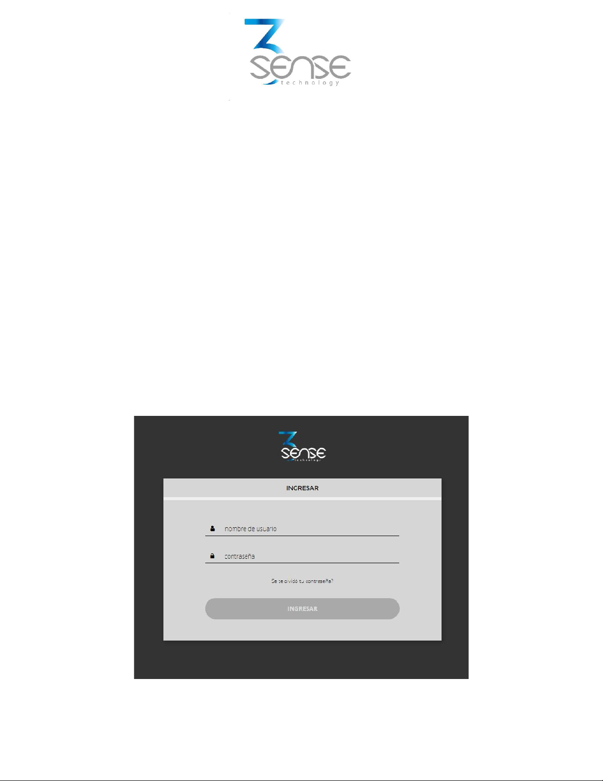
5.1. Access to Web Platform®
Using the credentials provided by the manufacturer, devices’ administrators ca n login at
login.3sense.tech:
Powered by
www.3sense.tech Nov. 2018
This device is part of 3Sense product family
The platform uses some basic elements to organize the information it manages, and facilitate
interaction with users. These are: Dashboards, Devices and Events.
An introduction to the use of each of them will be offered in this guide.
5.2. Reviewing One Device Historical Data
Dashboards are interfaces where relevant data is presented to the users. Web Platform® allows to
create custom Dashboards to integrate any information desired (if using an account with
permission to do so); however, by default it offers panels for remote monitoring of the data
published by each device linked to the platform, and panels to display Alarms or Events that have
recently occurred.
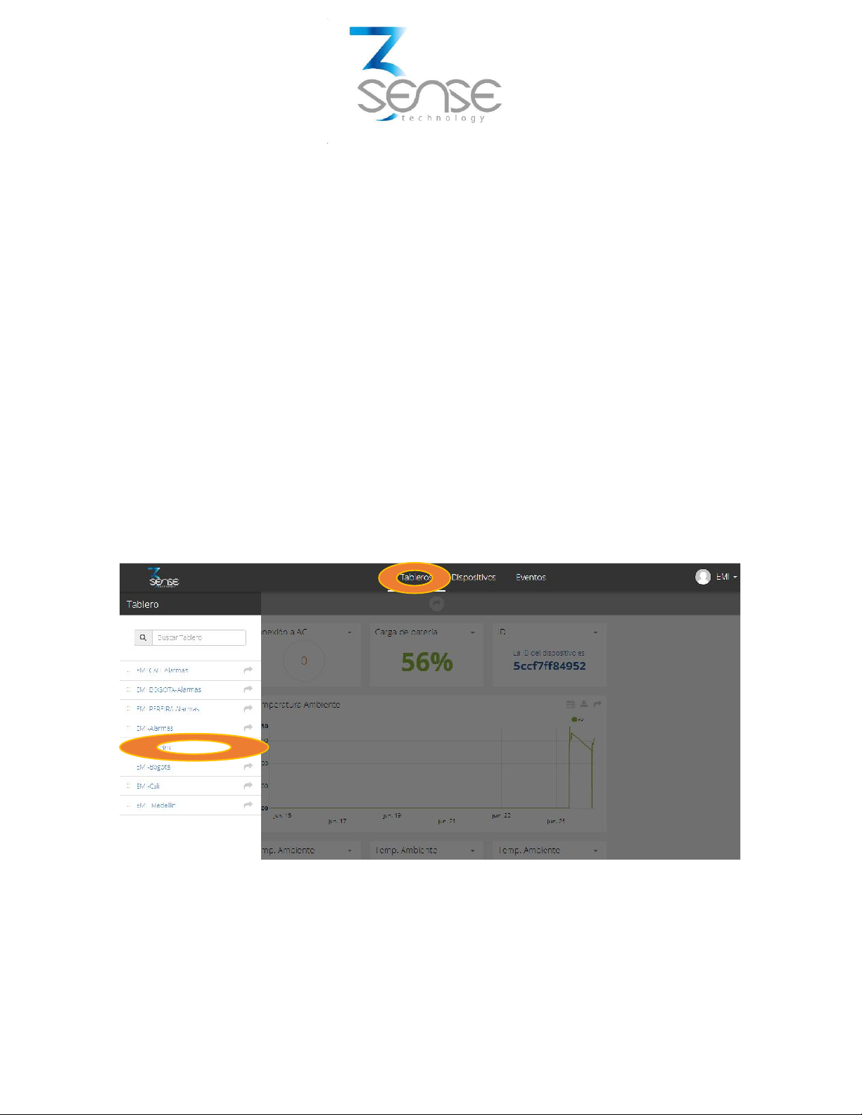
To review a Dashboard, initially follow what is indicated in 1.1, to access the platform.
Once inside, you can find the link to the section that includes all the Dashboards available to your
account, by clicking on the icon. Then, you can select the Board of your interest:
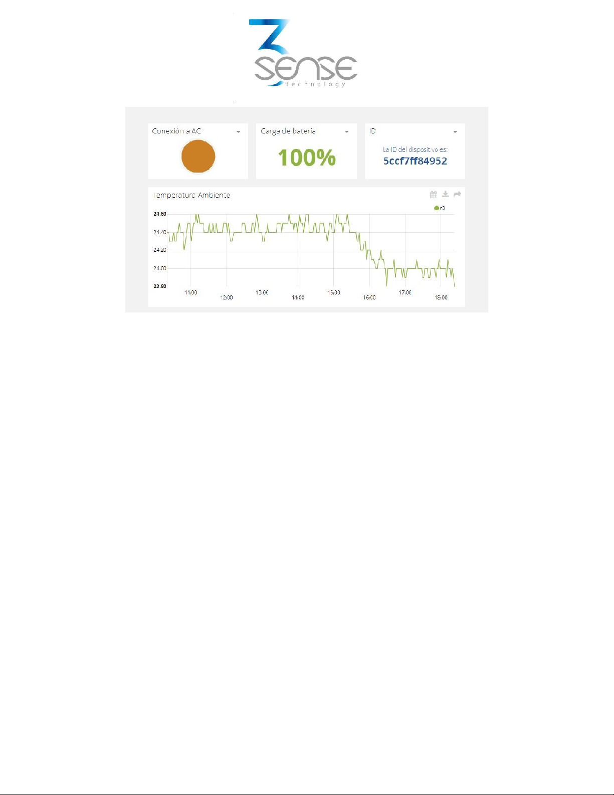
After selecting a particular Dashboard, the user is able to see the information that corresponds to
said panel in multiple graphs and visual elements:
Powered by
www.3sense.tech Nov. 2018
This device is part of 3Sense product family
To learn how to modify said elements and how to configure a Dashboard, refer to the
recommended manufacturer's guide.
5.3. Reviewing Devices, their Variables, and Configuration
A Device, in Web Platform®, is a virtual representation of a physical device that takes data from
sensors and transmits them through a particular network to the platform. Thus, each Device
visible to an account receives the data of the physical equipment acquired by the administrator of
said account.
The data received by a device is stored and organized in multiple variables.
To review a specific Device, initially follow what is indicated in 1.1, to access the platform.
Once inside, you can find the link to the section that includes all the available Devices to your
account and select the Device of your interest:

Powered by
www.3sense.tech Nov. 2018
This device is part of 3Sense product family
After selecting a particular Device, the user is able to see the information that corresponds to said
Device in multiple panels and Variables.
Reviewing the Variables of a certain Device allows checking the update status and presence of
each Variable. If is suspected that one variable is not being updated properly, after entering the
Device panel that should include it, its last activity period could be reviewed.
Powered by
www.3sense.tech Nov. 2018
This device is part of 3Sense product family
To learn how to modify the elements and configuration of a Device, refer to the manufacturer's
guide provided for it.
5.4. Reviewing Alarms and Programmed Events
In Web Platform®, Events (or Incidents) are configurable conditions that activate the sending of
alert messages via email, SMS messaging, Telegram messaging or Webhooks. Events that are in
condition to send a message, can be reviewed in a Board associated with your account, in whose
name the suffix -Alarms is included.
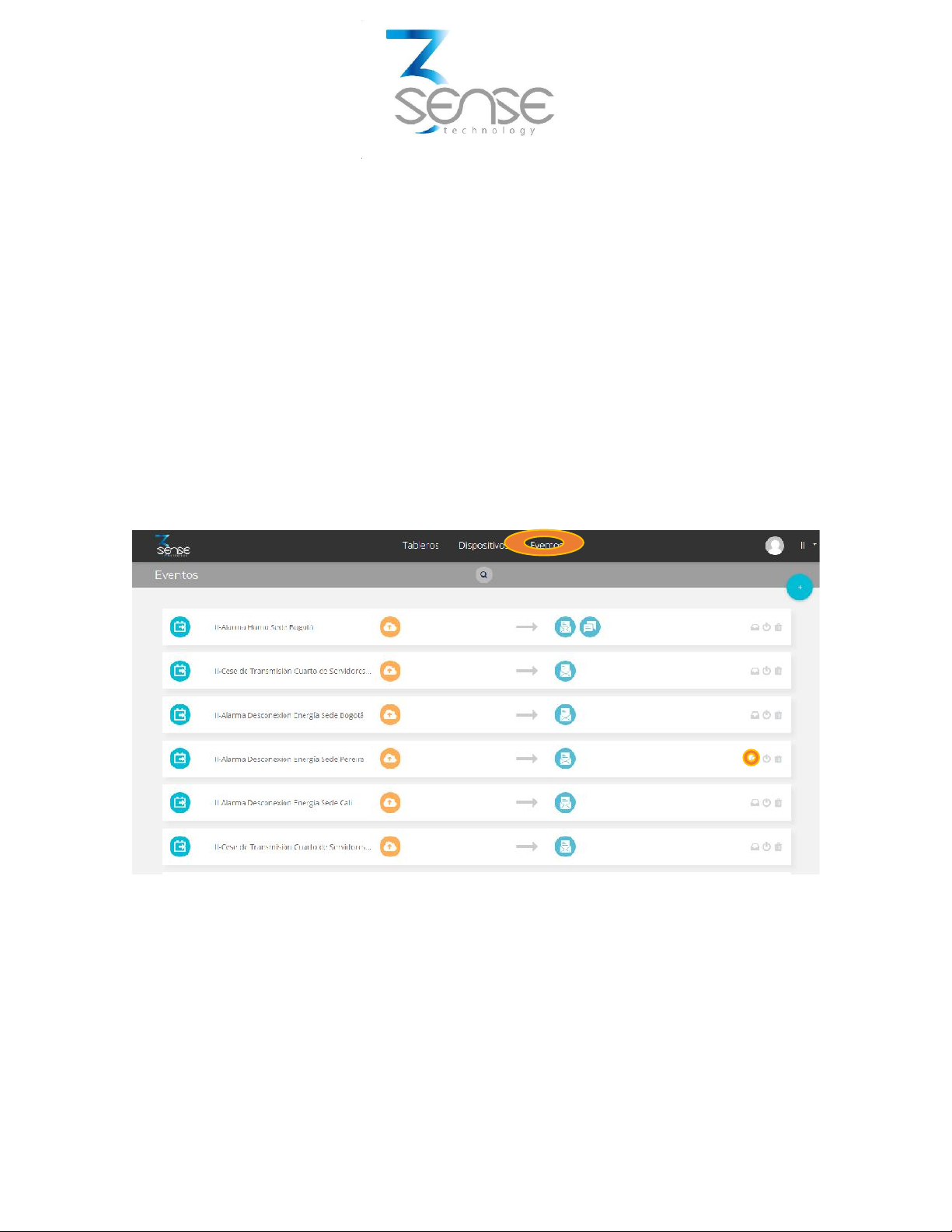
To review an Event, initially follow what is indicated in 1.1, to access the platform.
Once inside, you can find the link to the section that includes all Events available to your account
and locate the Event of your interest:
To review the last activity of an Event, the icon associated with each event can be clicked. By doing
so, you can view a table like the following:

Powered by
www.3sense.tech Nov. 2018
This device is part of 3Sense product family
To review the Dashboard with the recently activated Alarms, refer to section 1.2, and look for the
Dashboard whose name contains the suffix -Alarms.
This Dashboard will contain a table like the following:
To learn how to modify the elements and configuration of a Device, refer to the manufacturer's
guide, provided for it.
Remember that, if a certain explanation not clear, or you need more assistance, you can contact
the 3Sense technical service department. Contact Information can be found at the beginning of
this manual.
Table of contents


