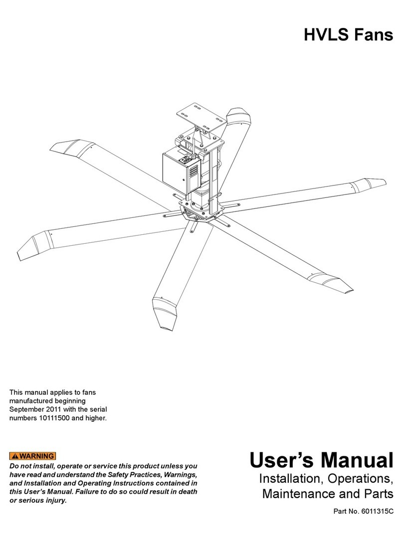
4Front Engineered Solutions HVLS User manual

Do not install, operate or service this product unless you
have read and understand the Safety Practices, Warnings,
and Installation and Operating Instructions contained in
this User’s Manual. Failure to do so could result in death
or serious injury.

Indicates an imminently hazardous situation which,
if not avoided, will result in death or serious injury.
Indicates a potentially hazardous situation which, if
not avoided, could result in death or serious injury.
Indicates a potentially hazardous situation which, if
not avoided may result in minor or moderate injury.
Notice is used to address practices not related to
personal injury.
This is the safety alert symbol. It is used
to alert you to potential personal injury
hazards. Obey all safety messages that
follow this symbol to avoid possible death or injury.

Read these safety practices before installing, operating
or servicing the fan. Failure to follow these safety
practices could result in death or serious injury.
READ AND FOLLOW THE OPERATING INSTRUCTIONS
IN THIS MANUAL BEFORE OPERATING THE FAN. If you
do not understand the instructions, ask your supervisor
to teach you how to use the fan.
Be certain to follow the instructions in this manual.
Variable Frequency Drive (VFD) fan controllers contain
high voltage capacitors. Before working on the fan
controller, ensure isolation of the main voltage supply
and verify voltage has bled off prior to beginning work.
Failure to do so may result in death or serious injury.


Fan Diameter
(Ft) Horse Power Hanging
Weight (Lb)
Maximum
Torque (Ft. Lb)
Typical
Spacing (Ft)
8 1 160
300
55
10 1 181 60
12 1 190 65
14 1 194 70
16 1 208 90
18 1 222 90
20 1 232 95
20 1-1/2 232 95
24 1 240 100
24 2 240 100

Fan information tag

Roof Slope 2/12 4/12 6/12 8/12 10/12
Roof Angle 9.5° 18.4° 26.6° 33.7° 39.8°
Fan Diameter (Ft) Recommended Extension Length (Ft) Exclusion Zone Radius (In.)
8 N/A N/A 1 1 2 15
10 N/A 1 1 2 3 18
12 N/A 1 2 3 4 22
14 1 2 3 4 5 26
16 1 3 4 5 7 29
18 2 3 5 6 8 33
20 2 4 5 7 9 36
24 3 5 7 9 11 44
Angled roof beam
Extension (optional)
Pendant
light
Exclusion zone
Length
(ft.)
36"
Roof slope = rise
run rise
run

Clamp
Clamp
Shim
A
Detail A
Universal
mounting
bracket

If building support beam is not level, ensure proper
fan clearance using the mounting information shown
on page 6 or add mounting extensions as required to
ensure clearance. See Fig. 3.
If a mounting extension has been used, it may be necessary
to obtain a longer cable from a local supplier.
Glulam bracket
Glulam

Failure to attach guy wires may result in loss of warranty.
If a mounting extension has been used, ensure that the
longer guy wires accompanying the extension are used.
Ensure that the angle formed by the guy wire with the
roof structure is less than 45º. See Fig. 8. Avoid any
sharp edges or corners to reduce fatiguing and fraying
of the guy wires.
Safety cable
Safety links Stop nut
Quick link
45° 45°

Failure to install the blade safety interlocks could result
in death or serious injury.
Blade strut
Blade
Winglet
Winglet
fasteners
6010843
6010844
Safety links Stop nut
Quick link

Before doing any electrical work, make certain the power
is disconnected and properly locked or tagged off. Failure
to do so may result in death or serious injury. All electrical
troubleshooting and repair must be done by a qualied
technician and meet all applicable codes. Do not route
control wiring for any other device through this control
box. Ensure that the voltage and phase of the incoming
power agrees with the VFD control panel and fan. Be certain
power is off when wiring to the control box. Failure to do
so could result in electrical shock, death or serious injury.
60"
Drive I/O (blue) MODBUS (gray)
Standard installation
SERVICE
Remote

Network Installation
Computer
Connector pin-out
Gateway Coupler
USB port
Category 5e ethernet cable
(supplied by 4Front)
Network Kit (6011464)
10321
1. White and orange
2. Orange
3. White and green
4. Blue
5. White and blue
6. Green
7. White and brown
8. Brown
Fan position number


Clamp
Shim Safety cable
Blade
Winglet
Motor
Gearbox
Universal mount
VFD control panel
Guy wires
Safety links

Fan speed control
Activation switch Standard installation only

Before operating the industrial fan, read and follow the
Safety Practices, Warnings and Operating Instructions
in this manual. Use by untrained personnel could result
in death or serious injury.
Ensure three position switch is in the off position before
supplying power to the fan. Allow 5 seconds for VFD to
stabilize before operating three position switch.

Before servicing the industrial fan, read and follow the
Safety Practices on page 3 and the Operation section
in this manual. Failure to do so could result in death or
serious injury.
To ensure the continued proper operation of your
industrial fan, perform the following planned maintenance
procedures.
Legend
Symbol Description
Cleaning
(Location - Frequency)
Blow with Compressed Air
(Location - Frequency)
Visually Inspect
(Replace Damaged Or Worn)
6011240 6009762

Before servicing the industrial fan, read and follow the
Safety Practices on page 3 and the Operation section
in this manual. Failure to do so could result in death or
serious injury.
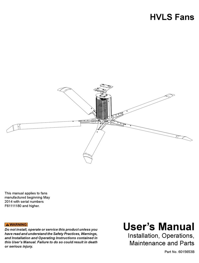
Before doing any electrical work, make certain the power
is disconnected and properly locked or tagged off. Failure
to do so may result in death or serious injury. All electrical
troubleshooting and repair must be done by a qualied
technician and meet all applicable codes. Do not route
control wiring for any other device through this control
box. Ensure that the voltage and phase of the incoming
power agrees with the VFD control panel and fan. Be certain
power is off when wiring to the control box. Failure to do
so could result in electrical shock, death or serious injury.

Service port
Patch cable
fan does not operate
Other manuals for HVLS
1
Table of contents
Other 4Front Engineered Solutions Fan manuals