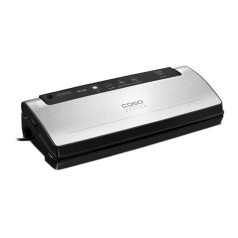
4titude 4s2 User manual

4s2
Variable Temperature Thermal Sealer
foto

4s2 Variable Temperature Thermal Sealer User Manual
All rights reserved.
No part of this publication may be reproduced, transmitted, transcribed, stored
in a retrieval system, or translated into any language, or computer language, in
any form, or by any means, electronic, mechanical, magnetic, optical, chemical,
or other, without the prior written permission of the manufacturer.
The manufacturer reserves the right to revise this publication and to make
changes from time to time in the contents hereof without obligation to notify any
person of such revision or changes.
Unless otherwise specified, references to names or parts are purely casual and
are used to illustrate the product described.
The document is for information only.
The manufacturer accepts no liability for errors contained herein or for incidental
or consequential damages with the performance or use of this material.
System Components
The following components are part of the 4s System (product code 4ti-0650):
• 4ti-0650 - 4s Heat Sealer
• Power Cable
• Manual & Quick User Guide
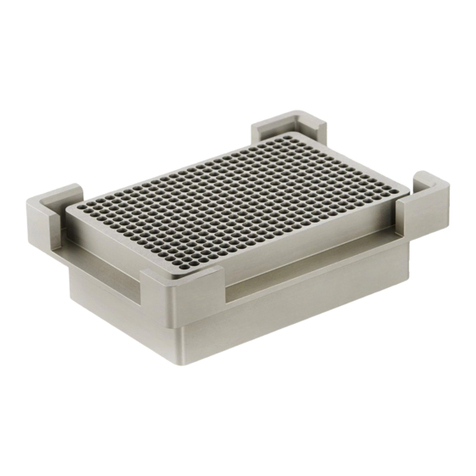
• 4ti-0615 - Plate Carrier
• 4ti-060 - Weighted Platten
Replacement accessories and optional extras are to be ordered separately.
• 4ti-06 5 - Plate carrier for 96well PCR Plates (optional extra)
• 4ti-061 - Sealing Frame (supplied FOC with 4ti-06 5)
• 4ti-06 6 - Warranty extension 1year (optional)
• 4ti-06 7 - Warranty extension years (optional)
Version: h 01/02/2010
i

PAG IND X
1 Introduction 1
1. Chapter Index
1.3 Safety
1.4 Applicable Rules 3
1.5 Technical Specifications 4
General Specification 5
.1 Sealer Parts 5
.1.1 Control Panel 6
.1. Rear Power Interface 7
3 Installation 8
3.1 Unpacking and start-up 8
3. Voltage Check 8
4 Set-Up 10
4.1 Set-Up Operating Mode 10
4. Set-Up, Stand-By, Power-Down, Buzzer 11
5 Basic Functions 1
5.1 Run Mode 1
5. Stand-By Mode 14
5.3 Power-Down Mode 14
5.4 Drawer Locking 14
6 Troubleshooting 15
6.1 Introduction 15
6. Error Messages 15
6.3 Cleaning the heating element 16
7 Maintenance 18
7.1 Regular Maintenance 18
8 Accessories & Consumables 19
8.1 Plate Types 19
8. Thermal Sealing Plastic and Sealing Film Types 19
8.3 Plate Carriers 19
9 Sealing Parameters 0
10 Shipping Instructions 1
11 Warranty
ii

1. INTRODUCTION
1.1 Introduction
The variable temperature thermal Sealer 4s2 is a semiautomatic instrument
designed to seal sample plates made from various polymers.
The sealer can be used with most plate types and sealing films available. Both
temperature and time are variable and can be optimised to suit each sealing
plate and film.
When the 4s is ready to start the operator needs to position the sample plate
together with a foil or film on the plate carrier. The sealing operation starts once
the drawer with the plate carrier has been closed. Film and sample plate will
then automatically be brought in contact with the heating element.
As soon as the sample plate is in contact with the heating element a countdown
timer starts and after the chosen sealing time the motor automatically moves the
sample plate away from the heating element and the operator can remove the
sealed sample plate for further processing.
Chapter
1
1

1.2 Chapter Index
To use the 4s correctly and to obtain the best results, please read this manual
carefully.
Chapter 1
Introduction
Warnings and Technical Specifications
Chapter 2
General Description
Chapter 3
Installation
Chapter 4
Set-Up
Chapter 5
Basic functions
Chapter 6
Troubleshooting
Chapter 7
Maintenance
Chapter 8
Accessories &
Consumables
1.3 Safety
Before using the sealer please read the following safety notes.
This product must only be used in accordance with proper safety standards and
procedures, together with the instructions included in this manual.
The sealer has been designed and manufactured to conform to international
safety specifications.
It’s essential that the users know the potential hazards associated with the
equipment.
All operators should know and observe the safety precautions and warnings
given in this section before starting to use the instrument.
If the unit is used in a way not specified by the manufacturer, the protection
provided by the equipment may be ineffective.

The following caution and safety signs are used in this manual:
WARNING:
Refer to manual
The machine is designed for indoor laboratory use only, at an altitude of less
than 00m above sea level, within a temperature range of 15°C to 35°C and a
relative humidity range of 5% to 85% non condensing.
If the instrument is stored outside these ranges, it should be left to stand until it
equilibrates to within the above limits.
Ensure that the voltage selection switch is set to the correct voltage and that the
correct fuse for the required voltage setting is fitted.
Do not work outside the rated power supply range.
Use the cleaning method recommended by the manufacturer.
Ensure the unit is only connected to an earthed supply.
There are no user accessible or serviceable parts inside the unit. Do not remove
the unit’s cabinet.
WARNING:
Hot surface
The hot plate can reach temperature up to 00°C,
Care must be taken not to touch it or serious burns may occur.
The equipment will maintain a high temperature for a considerable time after
switching off and it is essential to wait before starting cleaning operations.
Sealed sample plates may remain hot for some seconds after sealing and should
be handled with care.
WARNING:
Risk of electrical shock (high voltage)
This equipment should only be dismantled by properly trained personnel,
removing the top case exposes potentially lethal mains voltages.
1.4 Applicable rules
006/95/CE Low Voltage Directive
004/108/CE Electromagnetic Compatibility Directive
00 /96/CE amended 003/108/CE WEEE Directive
3

1.5 Technical Specifications
M CHANICAL
Dimensions
Height 310 mm.
Depth 275 mm.
Width 181 mm.
Weight
9
kg
L CTRICAL
Voltage 230/115/100 ±10% Vac
Frequency 47/63 Hz
Power 300 W
NVIRONM NTAL
Temperature range Operative: 18°C - 35°C
Storage: -20°C – 40°C
Relative humidity 20% - 80% not condensing
S T UP PARAM T RS
Sealing temperature: OFF or from 120°C to 200°C
Step: 1°C
Default: OFF
Sealing time: up to 10 seconds
Step: 0.5 seconds
Default: 3 seconds
Stand by cycle: “no” stand-by or from 1 to 99 minutes
Step: 1 minutes
Default: 60 minutes
Stand by temperature: 60°C, not programmable
Power down time: from 1 to 24 hours
Step: 1 hour
Default: 10 hours
Power down temperature: ambient
Warning sound (Buzzer): ON/OFF
Default: ON
4

2. G N RAL SP CIFICATION
2.1 Sealer Parts
• Casing (1)
• Control panel ( )
• Rear Power Interface (3)
• Heating element (4)
• Plate carrier (5)
• 96well PCR Plate Adapter (6) (optional)
• Weighted platten (7)
• Sealing Frame (8)
Chapter
2
5
1
3
4
5
6
7
Figure 1
8

• Control panel
Figure – Control Panel
Display:
Three Digit L D display
Keys:
(1) M: Set-up/Run mode key
(2)
: Directional key (up)
(3)
: Directional key (down)
Led:
(4) Status Indicator, Amber
1
2
3
4
6

2.1.2 Rear Power Interface
Figure 3– Rear Power Interface
1. Power Setting 115/230 Vac and Fuse Holder
. I/O Power Switch
3 Mains Power Plug
2
1
3
7

3. INSTALLATION
3.1 Unpacking and start-up
After unpacking retain all packing material and fixtures, as the unit must
always be transported in its original packaging to avoid damage.
The manufacturer accepts no responsibility for damage incurred unless the unit
is correctly packed and transported in this way.
Remove the 4s unit from its packaging.
The unit has to be placed on a level surface, away from direct sunlight
ensuring access to the power switch at the back of the unit.
Ensure that the vents on the casing are not obstructed.
The mains voltage selector switch should be checked to ensure that the voltage
has been set at the correct value.
Connect the unit to the mains power supply and switch on the switch I/O of
the rear power interface.
If the heater within the unit is receiving power the amber LED on the control
panel will be illuminated.
After switching on wait until the amber LED light stops flashing (the set
temperature is reached and the unit is ready to seal).
3.2 Voltage Check
Be sure that the equipment is not connected to the mains power.
At the rear of the 4s is the connection panel with
Power setting 30/115 Vac and Fuse Holder
I/O Power Switch
Mains Power Plug.
The set voltage is displayed in white on red background on the power setting
and fuse holder.
Chapter
3
8

Figure 3.A Figure 3B
To change the voltage setting proceed as follows:
1. Open fuse holder compartment with a screwdriver, figure 3A.
. With the screwdriver lever out the fuse holder, figure 3B.
3. Replace the two fuses according to the table below:
Power Voltage (EN 601 7)
115v 3.15A (T)
30v A (T)
Table
4. Insert the fuse holder keeping the set voltage label at the top.
5. Close the fuse compartment by pressing gently.
6. If the fuse holder is inserted correctly you can read the voltage selected.
9

4. S T-UP
4.1 Set-up Operating Mode
Power up the unit (switch on mains switch at the back of the unit).
To enter into the set-up mode for time and temperature settings, briefly press
and release the M key.
The display shows the last set sealing temperature (flashing).
The temperature can be decreased or increased using the keys
temperature “OFF” or between 1 0°C and 180°C with steps of 1°C.
see page 0 for recommended sealing temperatures.
By pressing the M key again the new temperature value is stored and the
sealing time can be set next.
The display shows the symbol “t” and the last set sealing time (flashing).
The sealing time can be decreased or increased with the keys
from 0-10 seconds in 0.5 second steps.
See page 0 for recommended sealing times.
Press the M key again to store the new sealing time value and to exit from the
set-up menu.
The unit returns into “run mode” (see page 1 ) and the actual temperature of
the heating element is shown in the display.
Chapter
4
10

4.2 Set-up, Stand-by, Power-down, Buzzer
To enter into set-up mode for stand-by, power-down and audible warning, press
the M key for 10 seconds, then release.
The display shows the symbol “L” (flashing) and the last set stand by time
(displayed as minutes).
The stand-by time is the time after which the heater temperature is
automatically reduced to 60°C when the unit is left idle.
The stand-by time can be decreased or increased with the keys
“no” stand-by or between 1 minute and 99 minutes with steps of 1minute.
By pressing the M key again the new stand by time is stored and the power-
down time can be set next.
The display shows the symbol “P” (flashing) and the last set power-down time
displayed as hours).
The power-down time is the time after which the heater is switched off
automatically when the unit is left idle.
The power down-time can be decreased or increased with the keys
between 1 hour and 4 hours with steps of 1 hour.
By pressing the M key again the new power down time value is stored and the
audible warning (buzzer) can be set next.
The display shows the symbol “S” (flashing) and the last set buzzer function.
The buzzer function can be enabled (“on”) or disabled (“no”) with the
keys.
By pressing the M key again the buzzer function is stored and the unit returns
into “run mode” (see page 1 ) and the actual temperature of the heating
element is shown in the display.
11

5. BASIC FUNCTIONS
5.1 “Run” Mode
Switch on the unit. The unit will automatically go into the starting position with
the drawer released and the plate lifting platform in “low” position.
In starting position the unit will automatically begin to warm up the heating
element. The display shows the temperature increase in real time with the amber
LED flashing.
When the heating element reaches the set temperature an audible beep is
emitted and the amber LED remains permanently illuminated.
The system is ready for sealing and the sample plate can be loaded onto the
appropriate plate carrier:
- All fully skirted SBS standard plates (except 96well PCR plates) can be loaded
onto the standard plate carrier. However, for easier handling of shallow well
plates we recommend to place the standard plate carrier (4ti-0615) inside the
adapter for 96well PCR plates (optional extra, code 4ti-06 5).
- All 96well PCR plates should be inserted into the 96well PCR plate adapter
(product code 4ti-06 5, see below). Note: When using the 96well PCR plate
adapter the standard plate carrier should be removed from the drawer.
Figure 4.B
The standard plate carrier can be
placed inside the adapter for
96well PCR plates (op
tional). This
assembly is recommended for
skirted shallow well plates such
as 384well PCR plates.
Chapter
5
Figure 5.A
Plate Adapter for 96well PCR Plates
(optional, code 4ti
-
0
6 5)
1
Figure 5.B
Plate Adapter for 96well PCR Plates
shown with non
-
skirted plate
Figure 4.A
Use the standard plate carrier for
deep well plates

Place the sealing film over the plate, ensuring that the sealing surface is face
down (Figure 6.A). When using heat sealing films that have a tendency to curl
(for example 4titude Peel Seal (product code 4ti-05 1), DMSO Resistant Seal
(4ti-0587) and Clear Weld Seal Mark II (4ti-0575)) use the sealing frame which is
supplied with the 4ti-06 5 adapter. For deep well plates place the weighted
platten on top of the sealing film (Figure 6.B). For most other plates we
recommend the use of the sealing frame (Figure 6.C).
Note: The sealing frame can only be used in conjunction with the 4ti-06 5
adapter
Push the drawer in fully and hold until you can hear the motor pushing up the
lifting platform which activates the door locking mechanism. The microplate with
the sealing film will now be lifted up and brought into contact with the heating
element.
Note: If the drawer is not pushed in fully the locking mechanism may fail and the
motor will stop moving. An error message will be displayed and a continuous
audible beep will be emitted. To rectify this and to continue with the sealing
process push the drawer in fully until you can a beep. If the problem persists it
may be necessary to switch the unit off and then on again.
As soon as the sample plate makes contact with the heating element the display
shows the symbol “t” and the countdown of the pre-selected sealing time starts.
When the countdown timer reaches zero the unit emits an audible beep. The
motor returns to the home position and the drawer is released. The operator can
pull out the drawer and remove the sealed plate.
The unit will emit an audible beep as soon as the heating plate has reached the
pre-selected temperature again and a new cycle can be started within a few
seconds.
NOT : Foil backed film may remain hot for a number of seconds after sealing.
Care should be taken in handling these plates.
13
Figure 7
Close the drawer
to start sealing.
Figure 6.A
Position sealing film on plate
Figure 6.B
Position weighted platten
above sealing film
Figure 6.C
Position sealing frame above
sealing film

5.2 “Stand-by” Mode
If left idle for a prolonged time the sealer will automatically switch into stand-by
mode (factory set at 60 minutes) and the temperature of the heating plate will
be reduced to 60°C.
When entering into stand-by mode the display shows the decrease of the
temperature in real time and the amber LED is switched off.
The temperature of the heating element will be maintained at 60°.
The display shows the actual temperature of the heating element and not the set
sealing temperature.
By pressing any key the unit will automatically begin to warm up the heating
plate to the pre-selected sealing temperature.
Refer to section 4. to change the time after which the unit switches into stand-
by mode or to switch off the stand-by function.
5.3 “Power-down” Mode
If the unit remains idle in stand-by mode for a prolonged time the system will go
into power down mode and the heating element will be switched off (factory set
at 10 hours). The amber LED is switched off.
The display shows the temperature decrease until it reaches 45°C, after this “LO”
will be displayed.
By pressing any key the unit will automatically begin to warm up the heating
element to the pre-selected sealing temperature.
Refer to section 4. to change the time after which the unit switches into power-
down mode.
5.4 Drawer Locking
It is possible to lock the drawer for transport or when the unit is not used to
prevent damage or dust contaminating the internal parts of the unit.
To lock the drawer proceed as follows:
• While pressing the key close the drawer
• The plate lifting platform moves up and the drawer is locked
• Switch OFF the unit
To unlock the drawer switch ON the unit.
14

6.TROUBL SHOOTING
6.1 Introduction
Possible error messages generated by the 4s are summarised in this chapter.
If the solutions given below do not solve the problem, please contact 4titude or
their authorised local distributor.
6.2 rror Messages
The display may show one of the following error codes. An intermittent audible
warning sound will be emitted at the same time.
r1: the system cannot reach the starting position within a defined
time
r2: the lifting platform does not remain in the elevated position
r3: the motor cannot move the lifting platform towards the
heating plate within a defined time
r4: the motor cannot move the lifting platform to the low position
within a defined time
r5 motor over current
r6 temperature sensor opened or disconnected
r7 “open drawer sensor” active during elevation movement;
r8 “platform in low position sensor” active during elevation
movement.
The errors will remain displayed until the problem is solved. To clear the error
please retry the operations that generated the error, e.g. error 7 may occur if the
drawer is pushed in but released before the motor sets in motion. To solve the
problem please push in the drawer again and hold until the motor is activated.
If any of the above errors persists switch “OFF” the unit and then switch “ON”
again.
If within 10 seconds the problem is not solved the heated plate is automatically
deactivated to avoid sample damage.
If the problem is solved within 10 seconds the unit will automatically return to
“run mode”.
Chapter
6
15

6.3 Cleaning the heating element
If the operator inserts the sealing film upside down on the microplate the sealing
film may get stuck on the heated sealing plate. To clean it proceed as follows:
Switch “OFF” the unit
Disconnect the unit from the mains power supply
Do not attempt to clean the unit until it has cooled down to near
room temperature
Release the lever on the back of the unit counterclockwise (see figure);
The drawer can now be fully removed from the unit
Peel off the sealing film by hand and clean with a paper towel if required.
Please note that the cleaning operation is much easier when the sealing film is
near ambient temperature!
16
Figure 8.A
Lever in “locked”
position
Figure 8.B
Remove drawer

Reinsert the drawer into the unit
Move the lever on the back of the unit clockwise to secure the drawer
mechanism (see figure)
Switch “ON” the unit.
17
Figure 8.C
Lever in “open”
position
Other manuals for 4s2
2
Table of contents
Other 4titude Food Saver manuals