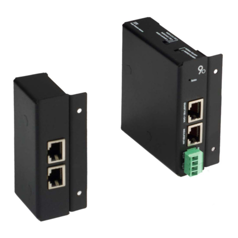
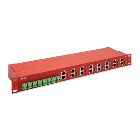
9dot LiteSync User manual

1
LITESYNC MANUAL VER. 2 REV. 0
LITESVNC

2
LITESYNC MANUAL VER. 2 REV. 0
Important notes .........................................................................................................................................................................3
Safety ..........................................................................................................................................................................................4
General warnings and precautions ............................................................................................................................................4
Certifications and compliances ..................................................................................................................................................4
Guarantee ...................................................................................................................................................................................4
General description ....................................................................................................................................................................5
LiteSync features ........................................................................................................................................................................6
Simple installation .............................................................................................................................................................................................................................. 6
Cambium Networks synchronization ................................................................................................................................................................................................. 6
Manages any type of PoE .................................................................................................................................................................................................................. 6
Certified partners ................................................................................................................................................................................................................................ 6
More power ........................................................................................................................................................................................................................................ 6
Short circuit and overvoltage protection ............................................................................................................................................................................................ 6
Galvanic isolation ............................................................................................................................................................................................................................... 6
Half unit rack mount ........................................................................................................................................................................................................................... 6
Label ........................................................................................................................................................................................................... 7
Technical specifications .............................................................................................................................................................8
Installation .................................................................................................................................................................................9
Physical interface ..................................................................................................................................................................... 10
LED coding ............................................................................................................................................................................................... 10
General state of the unit .................................................................................................................................................................................................................... 10
Legend LED 1 and LED 2 ................................................................................................................................................................................................................... 10
Blocks diagram ......................................................................................................................................................................... 11
Input power .............................................................................................................................................................................. 12
Special case -48V ............................................................................................................................................................................................................................ 12
Output power ........................................................................................................................................................................... 12
Synchronization pulse .............................................................................................................................................................. 13
GigaKey ............................................................................................................................................................................................................................................ 13
Synchronization ................................................................................................................................................................................................................................ 14
Official distributors ................................................................................................................................................................. 16

3
LITESYNC MANUAL VER. 2 REV. 0
Important notes
Warnings and cautions must be read and understood before installing 9dot products. Otherwise, personal injury could
occur.
The photographs, diagrams and figures contained in this manual are for illustrative purposes only. They may not
match to your installation.
9dot will not be liable for eventual damage or injury involving its hardware if it is used in any way inconsistent with
its intended purpose, or if it is installed or used in an untested manner or is improperly maintained.
The material in this document is for informational purposes only and is subject to change without notice. While
reasonable efforts have been made in the preparation of this document to ensure its accuracy, 9dot assumes no
responsibility for errors or omissions in this document or for the use of the information contained therein. 9dot
reserves the right to make changes to the design of the product without reservation and without prior notice to its
users.
The operator is advised to review the drawings and illustrations contained in this manual before proceeding. If you
have any questions regarding the safe operation of this power system, please contact 9dot or your nearest 9dot
distributor1.
For more information, visit www.9dot.it
For technical support, please contact:
Email: support@9dot.it
1
See section "Official Distributors"

4
LITESYNC MANUAL VER. 2 REV. 0
Safety
This manual contains important safety instructions that must be followed during installation, operation, and maintenance of
the product. Review the drawings and illustrations in this manual before proceeding. If you have any questions regarding the
safe installation or operation of this product, please contact 9dot or your nearest 9dot representative. Please keep it in a safe
place for future reference.
To reduce the risk of injury and to ensure continued safe operation of this product, the following terms have been incorporated
into this manual:
ATTENTION: indicates safety information intended to prevent damage to people, materials or equipment
IMPORTANT NOTE: additional clarifications on some features, terminology, reminders, etc.
Where they appear, please take more care and attention.
General warnings and precautions
You should read and understand the following warnings before installing the 9dot LiteSync and its components. Otherwise, it
could cause personal injury.
• Read and follow all instructions included in this manual.
• Don't work alone in dangerous conditions.
• Only qualified personnel may install, use, and repair this system and its components.
• Always assume electrical connections or conductors are live. Turn off all switches and recheck connections with a
voltmeter before installation or maintenance.
• Keep the installation area clean and dust-free during and after installation.
• Wear safety glasses when working in conditions that can be dangerous to the eyes.
Certifications and compliances
The equipment complies with ICES, FCC rules and regulations, European CE standard and RoHS directive.
Guarantee
To know the guarantee of our products, consult with our nearest distributor. See the “Official Distributors” section of this
document.

5
LITESYNC MANUAL VER. 2 REV. 0
General description
LiteSync is designed to supply power to devices on standard Power over Ethernet (PoE).
It is equipped with 2 integrated Gigabit Ethernet ports and can acquire the synchronization pulse via integrated GPS and Sync
Input port.
On the front there is a group of 3 LED that indicates the status of the unit and the synchronization presence.
It has 2 pairs of ports: injectors to power and synchronize devices in the lower part, connectors to connect the LAN network
in the upper part. Each single door has its own status LED.
On the front of the unit there are slots for inserting the GigaKey keys that allow you to select the output pin of the PoE port
without the use of microswitches in order to provide PoE to a wide range of devices.
LiteSync can be powered redundantly via two connectors. Each connector has its own power supply LED indicator. On the
back is the grounding terminal.
The Sync input port allows you to acquire the synchronization pulse from an external source through the RJ12 connector. You
can select the sync source (AUX: Sync input; GPS: GPS Antenna) through the source selector.
An external GPS antenna can be connected to this connector which will be used to generate synchronous pulses.
1
LED INDICATORS
2
POE PORTS
3
SLOT GIGAKEY
1
3
2
4
5
6
4
POWER CONNECTOR
5
SYNC INPUT PORT
6
ANTENNA CONNECTOR
Figure 1 - LiteSync unit
PotPORT
2
INSULATED
LAN
SYNC
INPUT
GPS
ANTENNA
MAIN
POWER
REDUNDANT
INPUT
(
24
-
60
V
DO
GiGABfT
Pot
+
DATA
UTESYNC
PoE
KYE
SLOT
I
UTESYNG
Pot
KYE
SLOT
2
QGA
8
IT
PoE
DATA

6
LITESYNC MANUAL VER. 2 REV. 0
LiteSync features
Simple installation
The LiteSync unit is ready to be installed. Just insert the GigaKey, connect the GPS antenna (if synchronization is required) and
power the device.
Cambium Networks synchronization
LiteSync can insert into the PoE ports the sync pulse used by Cambium Networks devices to sync the transmission.
Manages any type of PoE
Each port can be configured to handle a different type of injection map, with or without sync pulse. The configuration of the
power supply pinout is simple and does not require any IT skills: just insert the specific electronic GigaKey and the port is
configured.
Certified partners
LiteSync is a standard PoE injector capable to power any device in a range from 24V to 56V.
To offer increasingly heterogeneous and compatible solutions, we have also certified our product with the main vendors in
the TLC world, such as Cambium Networks, Ceragon and Intracom Telecom, who have tested their solutions both in the
laboratory and in the field.
Multiple and redundant temporization source
LiteSync has a built-in GPS receiver and can acts as master or slave with other units such us GigaSync or CMM5 (of Cambium
Networks) through the Sync Input port.
More power
Up to 3A (145W@48V) per port.
Short circuit and overvoltage protection
Connected devices are protected against short circuits, electrostatic surges and electric shocks. The combination of different
types of arresters maximizes efficiency and reduces the action time.
Galvanic isolation
Galvanic isolation protects circuits and people from overvoltage between the input side and the output side. This results in
the best protection for your devices and for you.
Half unit rack mount
LiteSync is 1U tall, can be installed in a rack using the half unit flange or paired with another LiteSync.

7
LITESYNC MANUAL VER. 2 REV. 0
Label
This device will have a label attached with relevant information us we describe below.
As we can see, on the label it is indicated:
The product code: GS-LT, with a brief description.
The serial number.
The part number P/N.
Indications in accordance with the standards FCC, CE and RoHS.
The indications of power requirements and the operating temperature range.
The image of the garbage container indicates that this equipment should not be placed in household containers. Instead, it
must be disposed of properly in compliance with current regulations.
Figure 2 - Example of LiteSync label
GS
-
LT
#
LiteSync
Serial
:
1
9
ma
@
1
Power
requirements
:
21.4
-
57
VDC
=
"
=
"
=
up
to
3
A
per
Port
Operating
temperature
:
-
20
to
+
45
°
C
Made
in
Italy
-
P
/
N
:
02101912110100
-
9
DOT
Srl
-
www
.
9
dot
.
it

8
LITESYNC MANUAL VER. 2 REV. 0
Technical specifications
BASE UNIT
Product code GS-LT
ELECTRICAL SPECIFICATIONS
Operating voltage [V] Clamps: +/- 24 to 60 DC
Main power connector 2 x wire terminals 2 x 1.31 mm2
Operating power [W]
< 4
GND connector
Screw M4
Active protection Short circuit protection, over voltage control, overload control
Unit led indicators Sync; Status and Alarm
Door led indicator LED RGB per port
Power LED indicator Power presence
Typical current per port [A] (*)
3
Typical current per unit [A] 6
Peak current protection [kA] 15
Overvoltage protection [V] 90
Protection mode All lines (1-8) protected (L-L) and (L-G)
SPD technology 2 phases: TVS, GDT
Gigabit transformer
SYNCHRONIZATION SPECIFICATIONS
External GPS connector N-Type female
Sync input compatibility GigaSync by 9dot; uGPS®, cnPulse® and CMM5® by Cambium Networks
Sync connectors Sync input: RJ12
Synchronicity method Cambium Sync
NETWORK/PoE SPECIFICATIONS
Ethernet / PoE connector Jack RJ45 shielded
Network transmission speed 10BaseT; 100BaseT; 1000BaseT
MECHANICAL SPECIFICATIONS
Dimensions (LxPxH) [mm] 218 x 135 (162 with antenna connector) x 45
Weight [Kg] 1
Material Varnished iron
ENVIRONMENTAL SPECIFICATIONS
Operating ambient temperature [°C] -20 to +45
Operating humidity without condensation
[%]
5 to 95
®
uGPS, cnPulse and CMM5 are trademarks or registered trademarks of Cambium Networks.
IMPORTANT NOTES:
(*) The typical current of 3 A per port can be achieved if the PoE configuration chosen to power a device is through
one of the GigaKey: GS-K-AB or GS-K-9.S because they both use all four pairs of conductors for power. If instead we
use the other GigaKeys: GS-K-B or GS-K-BR, the typical current per port will be 1.5A2.
(*) Although the typical value indicates that the current of 3A can flow continuously and indefinitely, this value should
not be exceeded.
2
See section “GigaKey”

9
LITESYNC MANUAL VER. 2 REV. 0
Figure 3 - LiteSync with fixing tabs at 90°
Installation
The LiteSync is designed for installation in a 19 "rack cabinet, however the fixing flaps can be rotated 90 ° for wall mounting.
Included are mounting tabs, one short and one long to complete the half rack unit.
IMPORTANT NOTE: Use only the fixing screws supplied with the device for fixing the fins; the use of different fixing screws
can cause irreparable damage to the device.
To the correct operation of the surge arresters, is essential to ground the rack cabinet and connect the grounding terminal on
the back.
This makes it possible to mount two LiteSync on one rack unit.
Figure 5 - two LiteSync on one rack unit
Figure 4 - long mounting flap to complete the half rack unit
I
k
&
o
o
9
hlKTi
H
HkHIIUII
IOUC
4
M
IP
.
'
mtBMU
IMAMU
*
y
.
w
>
i
+
w
i
!
LITE
-
r
»
i
f
iw
-
ftSUfBiA
hiwrj
muon
*
.
H
M
MM
MR
•
tr
’
''
•
-
TT
*
-
4
r
:
tT
4
l
*
MI
*
*
M
'
J
»
1
1
'
rm
»
jrrsW
(
fiC
<
r
-
?
KT
i
aswM
^
m
i
«
snc
\
c
»
W
2
O
0
Vht
-
ro

10
LITESYNC MANUAL VER. 2 REV. 0
Before turning on the device it is advisable to connect the ground terminal, fix the chassis to the cabinet or to the wall, insert
the chosen GigaKey keys and connect the signal cables, in particular:
• Ethernet cables.
• Coaxial cable and GPS antenna or cable with RJ12 connector (in case you need to acquire the sync pulse).
• Wire up the power supply (optional standalone power supply ACDC-48 or ACDC-24 supplied by 9dot).
• Connect the power supply pins of the power supply paying attention to the polarity adopted.
• Connect the power supply to the electricity.
These cables are not supplied with LiteSync and must be purchased separately3.
Physical interface
LED coding
General state of the unit
To know the general status of LiteSync, consider the first 3 LEDs arranged vertically on the left of the front.
LED Color Description
GPS green flashing 200ms
presence of the synchronization pulse from integrated GPS
AUX green flashing 200ms
presence of the sync pulse from the SYNC INPUT port
STATUS
Blue fixed
properly functioning device
Table 1 - general status indication LEDs
Legend LED 1 and LED 2
Color Description
Red flashing
port
disabled due to a short circuit
R
ed
GigaKey inserted incorrectly or invalid
Viol
et flashing
GigaKey is missing
Blue flashing
port enabled, no load connected
Blue port enabled with Cambium Sync and load detected
Table 2 - LED indications on the cartridge
3
Consultare la sezione “Antenna GPS” per vedere gli accessori venduti da 9dot

11
LITESYNC MANUAL VER. 2 REV. 0
Blocks diagram
The electronic design shows the presence of two main structures:
(•) a CPU guarantees the correct operation of all the basic electronics and performs the voltage and current
measurement
(•) the power components. The isolated converter is powered via one or both pairs of input terminals
The following is a schematic detail of the LiteSync design structure.
The power inputs, connectable through two redundant connectors, they have the negative pole interconnected and no
conversion is made to the applied voltage, so it will be the same voltage that comes out of the PoE port.
In this way it is possible to connect several voltages simultaneously, for example:
Input power 1
48V
Input power 2
24V
LED
MAIN INPUT POWER
CPU
SYNC
GPS
LED
SYNC IN
LEDs
VOLTAGE & LOAD
MEASUREMENT
GENERATION OF
SYNCHRONY
IMPULSES
KEY DETECTION
OUTPUT
PORTS
ON/OFF
PROTECTION
LED
REVERSE POLARITY
PROTECTION
CPU
HW
ISOLATED DCDC
converter
Figure 6 - Blocks diagram of the LiteSync electronic design

12
LITESYNC MANUAL VER. 2 REV. 0
Input power
The technical information of the input power is detailed below:
Input voltage Self-consumption Max load
Main input power +/- 24 - 60V DC 4W 360W
Table 3 - Voltage range, self-consumption and maximum load of the input power
To turn on the device it must be powered via redundant terminals on the front (optional standalone power supply ACDC-48
or ACDC-24 provided by 9dot).
The main input has an isolated DCDC converter that powers the CPU. In this way, maximum immunity from voltage surges
present on the power supply lines is guaranteed.
The main input admits polarity inversion, that is, a negative voltage can be connected to its terminals without problems.
IMPORTANT NOTES:
• The negative poles of the power connectors are directly connected. The reverse polarity protection does not protect
the device in the event that the two negative poles are connected to voltages not suitable for being short-circuited
together.
• The redundant power supply terminals can be used simultaneously, even with different voltages. In the case of two
different power supplies (for example 48V and 24V), LiteSync will power the output devices with the highest active
voltage.
Special case -48V
If you have a voltage of -48V (as often happens in some telecommunication systems), just connect the 0V cable to the positive
(+) terminal and the -48V to the negative (-) terminal according to the indications on the LiteSync silk-screen printing.
Output power
The main function of the PoE injector of this device is to allow the powering of other equipment on the network. LiteSync is a
passive injector.
IMPORTANT NOTES: Unlike active PoE, passive PoE does not use any protocol to determine the type of device to be powered;
it simply applies a type of voltage to its port without identifying which type of PoE standard or supply voltage the connected
load is compatible with. Using an unsuitable voltage and / or wrong pin out can cause irreparable damage to the powered
device.
It is possible to power a wide range of devices that accept different voltages as this cartridge essentially replicates the voltage
from the power terminals to the PoE output ports without applying any conversion.
This offers great versatility when it comes to connecting several PoE devices in the same infrastructure as each cartridge can
be powered at a different voltage than the rest.
In addition to supporting different voltages, the PoE Injector has the possibility to select the pin out of the PoE output ports,
by inserting a simple key, called GigaKey, thus allowing it to power a wide range of devices on the market.
To find out if your PoE device can be powered via LiteSync, just check the pin out that the GigaKey allows you to select and see
if it matches the input pin out of your equipment.4.
4
See the "GigaKey" section

13
LITESYNC MANUAL VER. 2 REV. 0
Special case -48V
There are facilities that require -48V power over the network, this option is perfectly feasible with LiteSync. We simply have
to connect the -48V to the input
5
and then choose the correct GigaKey in order to get -48V on the PoE ports based on the input
pin out of the devices we want to connect.
Protection
LiteSync detects the applied load value in real time. In the event of a sudden overload or short circuit, the protection intervenes
and interrupts the supply of the output voltage for 10 seconds. At the end of the period of inactivity, the voltage is supplied
again. During the period of suspension due to overload, the LED of the corresponding port flashes red.
On each port there are double phase surge arresters TVS (Transient Voltage Suppression) and GDT (Gas Discharge Tube).
Synchronization pulse
LiteSync offers the possibility to inject, through the same PoE port, the synchronization pulses compatible with the proprietary
Cambium Sync method that allows you to work with Gigabit Ethernet (1000BaseT). This means that the injector will allow
you to take advantage of the synchronization
6
of network devices compatible with the method mentioned above.
GigaKey
This is the generic name which identify the selection keys of the output pinout of each PoE port.
The GigaKey has been designed to avoid handling with the microswitches or jumpers that normally perform this function, but
are subject to errors. This simplifies selection, executable simply by inserting the chosen key into the slot corresponding to
the PoE port.
If desired, you can select a different GigaKey for each PoE port on the same cartridge.
At the moment, 4 different GigaKey have been developed that allow a wide range of compatibility between devices on the
market. They are easy to identify by their code and different colors.
Pinout GigaKey
Code
GS
-
K
-
9.S
GS
-
K
-
AB
GS
-
K
-
B
GS
-
K
-
BR
Name on the GigaKey
9.
SYNC
A+B
B
Brp
PoE mode A + B reverse polarization A + B B B reverse polarization
wires 1,2 DC + DC +
wires
3,6
DC
–
DC
–
wires 4,5 DC – DC + DC + DC –
wires 7,8 DC + DC – DC – DC +
COMPATIBILITY (*)
Cambium 450m
•
Cambium 450i • •
Cambium 450
•
IEEE 802.3af/at •
10/100Base
-
T PoE
•
1000Base-T PoE • •
Intracom / Siae • •
Mikrotik / Ubiquiti
• •
Ceragon •
Table 4 - Pinout GigaKey
5
As explained in the "Input power" section
6
See the "Synchronization" section
9
11
minim
mm
d
è
i
JU
&
JUl
9
o
9
.
SYNC

14
LITESYNC MANUAL VER. 2 REV. 0
(*) These are just some of the devices that can work with LiteSync. The list is very long, if you want to know if your equipment can connect to LiteSync, do not
hesitate to contact us.
Pay attention to the direction of insertion of the GigaKeys in the slots: the correct position is with the screen printing facing
upwards.
Synchronization
Many telecommunication networks require synchronization precision for their correct operation and, therefore, avoid self-
interference and reduce noise generated by the network. In this way, frequencies can also be reused and spectrally efficient.
This is possible to achieve if co-located devices are synchronized.
To synchronize the equipment, you must have a standard signal that serves as a reference to accurately determine the
corresponding data send and receive slots. This signal is known as a sync pulse and it will allow all synchronized devices to
send and receive data in the same period of time: uplink (sending data) and downlink (receiving data) so that when one
receives information, none of the others are sending.
The reference signal to generate the synchronization pulse, also known as "1PPS" or "pulse per second", can be obtained in
different ways:
Through the external GPS antenna
Through the LiteSync “Sync Input” port, connecting:
o “Sync output” port of GigaSync
o Cambium Networks uGPS
o Cambium Networks cnPulse
o Cambium Networks CMM5
With this sync pulse, the LiteSync can perfectly replicate the Cambium Networks sync mode as described in the following
table:
External antenna Sync Input
Method of synchronization GPSA (*) GigaSync uGPS cnPulse CMM5
Cambium Sync
(§)
Table 5 - Several ways to obtain Cambium Networks synchronization method
(*) Product sold by 9dot. It must be purchased separately.
(§) It depends on the source of synchronization that provides the pulse.
GPS antenna
The external antenna must be connected to the N-type female connector that is installed on the front of the LiteSync and
requires a good view of the sky. It does not need to be mounted at the highest point of the tower.
Products sold by 9dot
Supplied with every LiteSync, 9dot provides a compatible GPS antenna; also available separately.
9dot can also provide the coaxial cables needed to connect the antenna to the chassis which must be purchased separately.
Below are the details of these products:
Product code
(*)
Description
GS
-
GPSA
Universal
GPS
antenna with mounitng
kit
N2N5LMR RF Cable 400 N/M - N/M Length. 5mt
N2N10LMR RF Cable 400 N/M - N/M Length. 10mt
N2N20LMR
RF Cable
400 N/M
-
N/M
Length
. 20mt
ACDC-48 Standalone AC / DC CONVERTER 48V 350W power supply. Cables are not included
ACDC-24 Standalone AC / DC CONVERTER 24V 350W power supply. Cables are not included
Table 6 - accessories supplied by 9dot

15
LITESYNC MANUAL VER. 2 REV. 0
The antenna connected to the LiteSync must be active; the GPS chip integrated in the LiteSync supplies a 3.3V DC voltage on
the N connector, to power the filters and amplifiers inside the antenna; for the same reason it is essential, to ensure the
operation of the GPS system, that the RF protections inserted between LiteSync and GPS antenna allow the power to pass
through (DC Pass).
Sync Input
Sync Input is a port used to acquire the sync pulse that does not come directly from an external antenna.
Pinout Sync Input
RJ1
2
Pin
Sync
V
olta
g
e
range
1 RX + 5 – 12V DC
2 n/c
3 n/c
4 n/c 5V (power to uGPS/cnPulse)
5
GND
6 GND
Table 7 - LiteSync sync input port pin out
uGPS
You can connect a Cambium Networks uGPS device to the Sync Input port.
cnPulse
cnPulse is the new version of the sync generator from Cambium Networks.
CMM5
CMM5 is a cluster management module manufactured by Cambium Networks that replicates the device's sync pulse through
an output port. If you have a CMM5 in your configuration, you can get the sync pulse and connect it to the LiteSync sync input
port. This will allow you to generate the Cambium Sync method.

16
LITESYNC MANUAL VER. 2 REV. 0
Official distributors
EUROP
A
, ASIA
&
AFRICA
Telcomms Srl
Via Giuntini 25 int. 22
56023 Navacchio (PI), Italy
(+39) 050 8068086
www.telcomms.it
Skylinks Telecoms
Unit 31, Ramstown, Gorey Business Park, Co.
Wexford, Y25 HC67, Ireland
0402 21955
www.skylinkstelecoms.ie
VanCo
U Čokoládoven 9
143 00 Praha 12, Czech Republic
+420 246 035 451
www.vanco.cz
Wifidom
Offices
Calle Valencia 63
08015 Barcelona, Spain
Headquarters
Avenida de la Industria, 32 28108 Madrid,
Spain
Offices
(+34) 933 90 59 54
Headquarters
(+34) 918 29 77 85
info@wifidom.com
www.wifidom.com
Winncom Technologies Regional
Presence
Ireland
Suite 144 The Capel Building Suite 5, Mary's
Abbey,
Dublin 7, Ireland
+353 1 871-6316
www.winncom.com

17
LITESYNC MANUAL VER. 2 REV. 0
USA & CANADA
Streakwave Wireless, Inc. Headquarters
840 Jury Ct, San Jose, CA 95112, USA
Utah sales and distribution
1420 S 4800 W Suite B, Salt Lake City, UT
84104, USA
Ohio sales and distribution
11777 Enterprise Dr, Cincinnati, OH 45241,
USA
(888) 604-5234
www.streakwave.com
Winncom Technologies World Headquarters
28900 Fountain Pkwy, Unit B Solon, Ohio
44139, USA
+1 (440) 498-9510
www.winncom.com
LATINA AMERICA
&
THE CARIBBEAN
Winncom Technologies CALA Offices
3840 W 104th Street, Unit 6, Hialeah, FL 33018, USA
440-519-2984 or 1-888-946-6266 EXT 146
Spanish and English
sales.latinamerica@winncom.com
www.winncom.com
Visit us on our website: www.9dot.it
9dot is a registered trademark of 9dot in the European Union. Copyright © 2020 9dot.
Due to continuous product development, 9dot reserves the right to change specifications without prior notice.
CENTRAL ASIA & AUSTRALIA
Winncom Technologies Regional Presence
Uzbekistan
35, 6th passage, A. Kahhar St., Tashkent
100025, Uzbekistan
+99 (871) 150-3939
+99 (871) 150-2679
For US callers: 1 (440) 505-0135 office code
802, Operator: 309, Sales: 332/333
sales.ca@winncom.com
www.winncom.uz
Streakwave Pty Ltd
Ground Floor - 470 St Kilda Road
MELBOURNE VIC 3004
+61 3 9001 4295
sales@streakwave.com.au
Table of contents
Other 9dot Laboratory Equipment manuals
Popular Laboratory Equipment manuals by other brands

Matrix
Matrix WellMate user manual

Labnet
Labnet VorTemp 1550 instruction manual

Agilent Technologies
Agilent Technologies PSG Series Service guide

Nippon Genetics
Nippon Genetics FastGene FAS-Digi PRO manual

Thermo Scientific
Thermo Scientific OWL HEP-1 Operating and maintenance manual

Hanil
Hanil Fleta 5 quick guide