A-EON COBRA 50 2007 User manual

2007 NEW COBRA 50
SERVICE MANUAL
FOREWORD
This service manual is designed primarily for use by certified Aeon Master Service
Dealer technicians in a properly equipped shop and should be kept available for
reference. All references to left and right side of the vehicle are from the operator's
perspective when seated in a normal riding position.
Some procedures outlined in this manual require a sound knowledge of mechanical
theory, tool use, and shop procedures in order to perform the work safely and correctly.
Technicians should read the text and be familiar with
service procedures before starting
the work. Certain procedures require the use of special tools. Use only the proper tools
as specified.
UNDERSTANDING MANUAL SAFETY LABELS AND DIRECTIONS
Throughout this manual, important information is brought to your attention by the following symbols:
SAFETY ALERT WARNING indicates a potential hazard that may result in severe injury or death to the operator, bystander
or person(s) inspecting or servicing the vehicle.
SAFETY ALERT CAUTION indicates a potential hazard that may result in minor personal injury or damage to the vehicle.
CAUTION indicates special precautions that must be taken to avoid vehicle damage or property damage.
NOTE:
NOTE provides key information by clarifying instructions.
IMPORTANT:
IMPORTANT provides key reminders during disassembly, assembly and inspection of components.

1
GENERAL INFORMATION 1
MAINTENANCE 2
CVT 3
ENGINE / TRANSMISSION 4
FUEL SYSTEM 5
BODY / SUSPENSION / STEERING 6
BRAKES 7
ELECTRICAL 8
2
3
4

GENERAL INFORMATION
CHAPTER 1
GENERAL INFORMATION 1
INFORMATION . . . . .……………... . . . . . . . . . . . . . . . . . . . . . . . . . . . . . . . . . . . . . . . . . . 1.2
ENGINE SERIAL NUMBER LOCATION . . . . . . . . . . . . . . . . . . . . . . . . . . . . . . . . . . . . . 1.2
VEHICLE IDENTIFICATION NUMBER LOCATION. . . . . . . . . . . . . . . . . . . . . . . . . . . . . 1.2
GENERAL SPECIFICATIONS . . . . . . . . . . . . . . . . . . . . . . . . . . . . . . . . . . . . . . . . . . . . . . 1.3
MODEL: 2007 NEW COBRA 50 . . . . . . . . . . . . . . . . . . . . . . . . . . . . . . . . . . . . . . . . . . . 1.3
VEHICLE COMPONENT INSPECTION LOCATIONS………………………………………1.4
1.1
5GENERAL INFORMATION
6MODEL INFORMATION
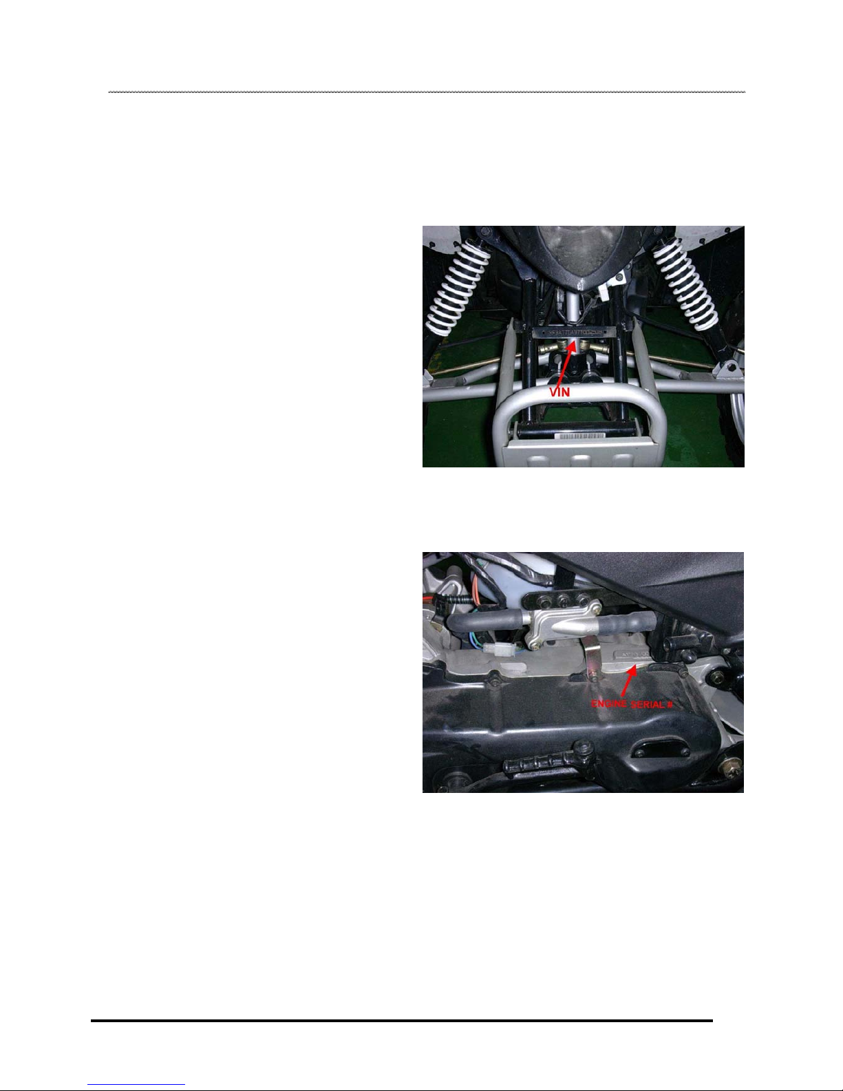
VIN Identification
Engine Serial Number Location
Whenever corresponding about an engine, be sure to refer to
the engine serial number. This information can be found
stamped on the top LH side of the crankcase as shown below.
Vehicle Identification Number Location
The vehicle identification number (VIN) and engine serial
number are important for identification purposes. See the
illustrations
1.2

GENERAL INFORMATION
8
GENERAL SPECIFICATIONS
DESCRIPTION COBRA 50
ENGINE TYPE 2-Stroke, Horizontal
DISPLACEMENT 49.3 cc
BORE STROKE 40*39.2
COMPRESSION RATIO 7.6:1
MAX. TORQUE 3.73 N-m/ 5724 rpm
STARTING Electric/ Kicker
LUBRICATION / OIL CAPACITY Oil Injection / 1 Liter
TRANSMISSION Automatic (C.V.T system)
TIRE FRONT 19*7-8
REAR 18*9.5-8
OVERALL DIMENSION 1676*961.5*1007 mm
GROUND CLEARANCE 112 mm
SUSPENSION FRONT Duo- shocks with single A-arm
REAR Swing arm with Single shock
BRAKE FRONT Drum
REAR Disc
WHEELBASE 1051 mm
SEAT HEIGHT 800 mm
DRY WEIGHT 129 kg
MAX. LOAD 140 kg
FUEL Unleaded Gasoline
FUEL CAPABILITY 5 Liter
1.3
GENERAL INFORMATION
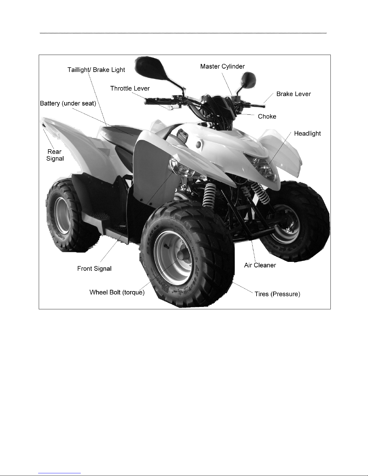
Vehicle Component Inspection Location

MAINTENANCE CHAPTER 2
MAINTENANCE
PERIODIC MAINTENANCE CHART. . . . . . . . . . . . .. . . . . . . . . . . . . . . . . . . . . . . . . . . . . 2.3
PERIODIC MAINTENANCE OVERVIEW. . . . . . . . . . . . . . . . . . . . . . . . . . . . . . . . . . . . . 2.3
PRE-RIDE - 40 HOUR MAINTENANCE INTERVAL . . . . . . . . . . . . . . . . . . . . . . . . . . . . 2.4
50 - 300 HOUR MAINTENANCE INTERVAL . . . . . . . . . . . . . . . . . . . . . . . . . . . . . . . . . . 2.5
GENERAL VEHICLE INSPECTION AND MAINTENANCE. . . . . . . . . . . . . . . . . . . . . . . . 2.6
FRAME, NUTS, BOLTS AND FASTENER INSPECTION . . . . . . . . . . . . . . . . . . . . . . . . 2.6
STANDARD TORQUE SPECIFICATIONS. . . . . . . . . . . . . . . . . . . . . . . . . . . . . . . . . . . . 2.6
KICK-START LEVER AND OPERATION. . . . . . . . . . . . . . . . . . . . . . . . . . . . . . . . . . . . . 2.6
FUEL SYSTEM AND AIR INTAKE . . …. . . . . . . . . . . . . . . . . . . . . . . . . . . . . . . . . . . . . . . 2.7
FUEL SYSTEM SAFETY . . . . . . . . . . . . . . . . … . . . . . . . . . . . . . . . . . . . . . . . . . . . . . . . 2.7
SPEED CONTROL SYSTEM . . . . . . . . . . . . . . . . . … . . . . . . . . . . . . . . . . . . . . . . . . . . . 2.7
THROTTLE STOP SPEED CONTROL SYSTEM. . . . . . . . . ... . . . . . . . . . . . . . . . . . . . . 2.8
CHOKE CABLE ADJUSTMENT. . . . . . . . . . . . . . . . . . . . . . . . . . . . ... . . . . . . . . . . . . . . 2.8
IDLE SPEED ADJUSTMENT . . . . . . . . . . . . . . . . .. . . . . . . . . . . . . . . . . . . . . . . . . . . . . 2.8
FUEL LINES . . . . . . . . . . . . . . . . . . . . . . . . . . . . . . . . . . . . . . . . . . . . . . . . . . . . . . . . . . 2.8
PILOT AIR SCREW ADJUSTMENT. . . . . . . .. . . . . . . . . . . . . . . . . . . . . . . . . . . . . . . . . 2.9
FUEL FILTER . . . . . . . . . . . . . . . . . . . . . . . . . . . . . . . . . . .. . . . . . . . . . . . . . . . . . . . . . . 2.9
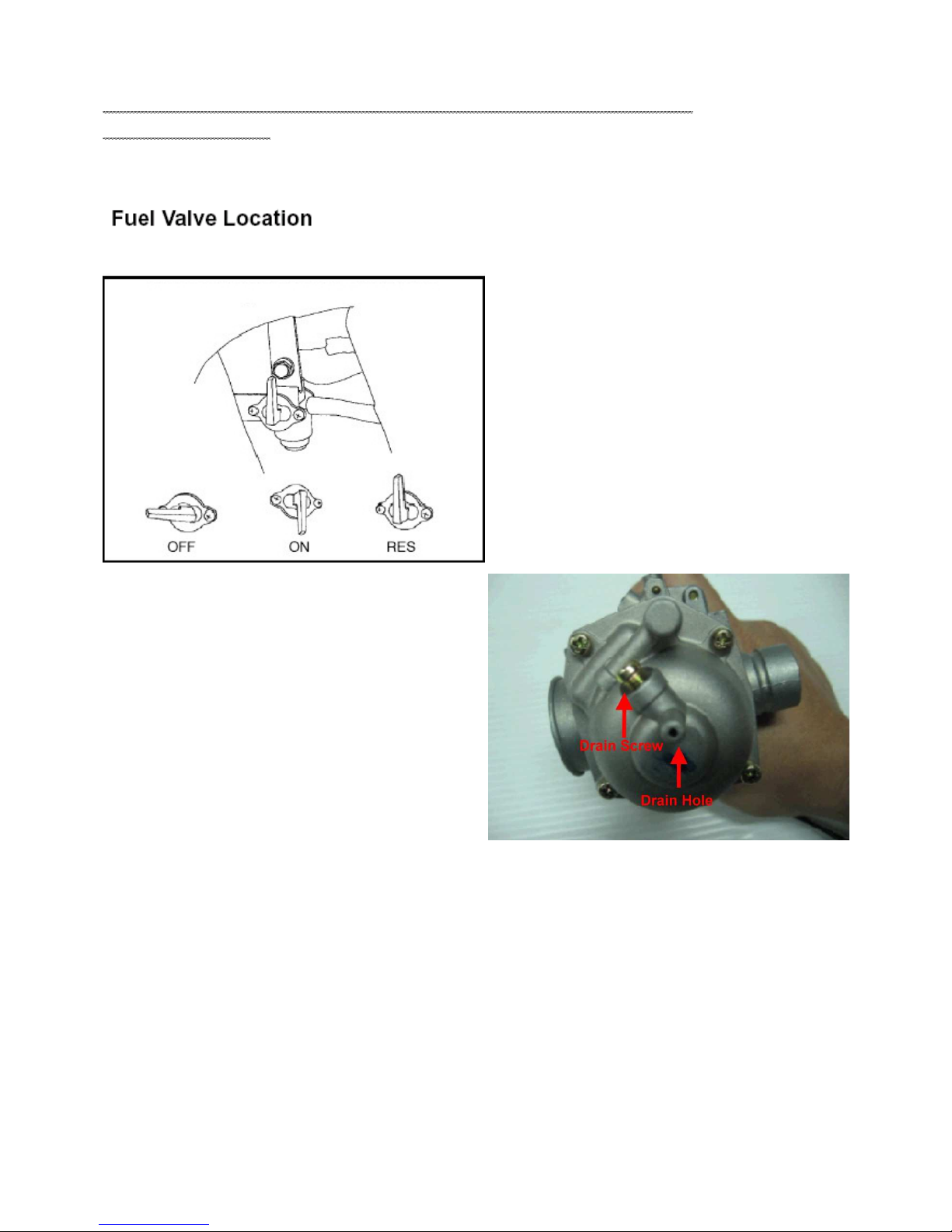
FUEL VALVE LOCATION. . . . . . . . . . . . . . . . . . . . . . . . . . . . . . . . . . . . . . . . . . . . . . . . 2.10
CARBURETOR DRAINING . . . . . . . . . . . . . . . . . . . . . . . . . . . . . . . . . . . . . . . . . . . . . . 2.10
AIR FILTER SERVICE . . . . . . . . . . . . . . . . . . . . . . . . . . . . . . . . . . . . . . . . . . . . . . . . . . 2.11
ENGINE . . . . . . . . . . . . . . . . . . . . . . . . . . . . . . . . . . . . . . . . . . . . . . . . . . . . . . . . . . . . . . 2.12
ENGINE OIL LEVEL . . . . . . . . . . . . . . . . . . . . . . . . . . . . . . . . . . . . . . . . . . . . . . . . . . . . 2.12
ENGINE OIL AND FILTER CHANGE. . . . . . . . . . . . . . . . . . . . . . . . . . . . . . . . . . . . . . . 2.12
ENGINE MOUNTS . . . . . . . . . . . . . . . . . . . . . . . . . . . . . . . . . . . . . . . . . . . . . . . . . . . . . 2.13
ENGINE FASTENER TORQUE . . . . . . . . . . . . . . . . . . . . . . . . . . . . . . . . . . . . . . . . . . . 2.13
CVT DRYING. . . . . . . . . . . . . . . . . . . . . . . . . . . . . . . . . . . . . . . . . . . . . . . . . . . . . . . . . . 2.13
TRANSMISSION AND FINAL DRIVE . . . . . . . . . . . . . . . . . . . . . . . . . . . . . . . . . . . . . . . 2.14
TRANSMISSION LUBRICATION . . . . . . . . . . . . . . . . . . . . . . . . . . . . . . . . . . . . . . . . . . 2.14
TRANSMISSION LUBRICANT LEVEL. . . . . . . . . . . . . . . . . . . . . . . . . . . . . . . . . . . . . . 2.14
TRANSMISSION LUBRICANT CHANGE. . . . . . . . . . . . . . . . . . . . . . . . . . . . . . . . . . . . 2.14
DRIVE CHAIN INSPECTION -. . . . . . . . . . .. . . . . . . . . . . . . . . . . . . . . . . . . . . . . . . . . . 2.15
DRIVE CHAIN ADJUSTMENT - . . . . . . . . . . . . . . . . . . … . . . . . . . . . . . . . . . . . . . . . . . 2.15
SPROCKET INSPECTION . . . . . . . . . . . . . . . . . . . . . . . . . . . . . . . . . . . . . . . . . . . . . . . 2.16
ELECTRICAL AND IGNITION SYSTEM . . . . . . . . . . . . . . . . . . . . . . . . . . . . . . . . . . . . . 2.17
BATTERY REMOVAL. . . . . . . ... . . . . . . . . . . . . . . . . . . . . . . . . . . . . . . . . . . . . . . . . . . 2.17

2.1
BATTERY CLEANING . . . . . . . . . . . . . . . . . . . . . . . . . . . . . . . . . . . . . . . . . . . . . . . . . . 2.17
BATTERY INSTALLATION. . . . . . . . . . . . . . . . . . . . . . . . . . . . . . . . . . . . . . . . . . . . . . . 2.17
BATTERY STORAGE. . . . . . . . . . . . . . . . . . . . . . . . . . . . . . . . . . . . . . . . . . . . . . . . . . . 2.17
FUSES / FUSE HOLDER LOCATION . . . . . . . . . . . . . . . . . . . . . . . . . . . . . . . . . . . . . . 2.18
SPARK PLUG INSPECTION . . . . . . . . . . . . . . . . . . . . . . . . . . . . . . . . . . . . . . . . . . . . . 2.18
STEERING AND SUSPENSION . . . . . . . . . . . . . . . . . . . . . . . . . . . . . . . . . . . . . . . . . . . 2.19
STEERING . . . . . . . . . . . . . . . . . . . . . . . . . . . . . . . . . . . . . . . . . . . . . . . . . . . . . . . . . . . 2.19
TIE ROD END / STEERING INSPECTION . . . . . . . . . . . . . . . . . . . . . . . . . . . . . . . . . . 2.20
WHEEL ALIGNMENT. . . . . . . . . . . . . . . . . . . . . . . . . . . . . . . . . . . . . . . . . . . . . . . . . . . 2.20
TOE ADJUSTMENT . . . . . . . . . . . . . . . . . . . . . . . . . . . . . . . . . . . . . . . . . . . . . . . . . . . . 2.21
FRONT SUSPENSION INSPECTION . . . . . . . . . . . . . . . . . . . . . . . . . . . . . . . . . . . . . . 2.21
REAR SUSPENSION INSPECTION . . . . . . . . . . . . . . . . . . . . . . . . . . . . . . . . . . . . . . . 2.22
SUSPENSION SPRING ADJUSTMENT . . . . . . . . . . . . . . . . . . . . . . . . . . . . . . . . . . . . 2.22
BRAKE SYSTEM. . . . . . . . . . . . . . . . . . . . . . . . . . . . . . . . . . . . . . . . . . . . . . . . . . . . . . . 2.22
BRAKE SYSTEM INSPECTION. . . . . . . . . . . . . . . . . . . . . . . . . . . . . . . . . . . . . . . . . . . 2.22
BRAKE LEVER TRAVEL . . . . . . . . . . . . . . . . . . . . . . . . . . . . . . . . . . . . . . . . . . . . . . . . 2.22
BRAKE FREEPLAY . . . . . . . . . . . . . . . . . . . . . . . . . . . . . . . . . . . . . . . . . . . . . . . . . . . . 2.23
FRONT BRAKE ADJUSTMENT. . . . . . . . . . . . . . . . . . . . . . . . . . . . . . . . . . . . . . . . . . . 2.23
WHEELS AND TIRES . . . . . . . . . . . . . . . . . . . . . . . . . . . . . . . . . . . . . . . . . . . . . . . . . . . 2.24
WHEELS. . . . . . . . . . . . . . . . . . . . . . . . . . . . . . . . . . . . . . . . . . . . . . . . . . . . . . . . . . . . . 2.24
WHEEL, HUB AND SPINDLE TORQUE TABLE . . . . . . . . . . . . . . . . . . . . . . . . . . . . . . 2.24
WHEEL INSPECTION . . . . . . . . . . . . . . . . . . . . . . . . . . . . . . . . . . . . . . . . . . . . . . . . . . 2.24
WHEEL REMOVAL - FRONT / REAR . . . . . . . . . . . . . . . . . . . . . . . . . . . . . . . . . . . . . . 2.24
WHEEL INSTALLATION - FRONT / REAR . . . . . . . . . . . . . . . . . . . . . . . . . . . . . . . . . . 2.24
TIRE PRESSURE. . . . . . . . . . . . . . . . . . . . . . . . . . . . . . . . . . . . . . . . . . . . . . . . . . . . . . 2.25
TIRE INSPECTION. . . . . . . . . . . . . . . . . . . . . . . . . . . . . . . . . . . . . . . . . . . . . . . . . . . . . 2.25
2.2
MAINTENANCE
PERIODIC MAINTENANCE CHART
Periodic Maintenance Overview
Careful periodic maintenance will help keep your vehicle in the safest, most reliable condition. Inspection,
adjustment and lubrication of important components are explained in the periodic maintenance chart.
Inspect, clean, lubricate, adjust and replace parts as necessary. When inspection reveals the need for replacement
parts, use genuine Polaris parts available from your dealer.
NOTE: Service and adjustments are critical. If you’re not familiar with safe service and adjustment procedures, have
qualified dealer perform these operations.
Maintenance intervals in the following chart are based upon average riding conditions and an average vehicle speed
of approximately 10 miles per hour. Vehicles subjected to severe use must be inspected and serviced more
frequently.
Severe Use Definition
• Frequent immersion in mud, water or sand
• Racing or race-style high RPM use
• Prolonged low speed, heavy load operation
• Extended idle
• Short trip cold weather operation
Pay special attention to the oil level. A rise in oil level during cold weather can indicate contaminants collecting in
oil sump or crankcase. Change oil immediately if the oil level begins to rise. Monitor the oil level, and if it continues
rise, discontinue use and determine the cause or see your dealer.
Maintenance Chart Key
The following symbols denote potential items to be aware of during maintenance:
■ = CAUTION: Due to the nature of these adjustments, it is recommended this service be performed by
authorized Polaris dealer.
◆ = SEVERE USE ITEM -- See Above
NOTE: Inspection may reveal the need for replacement parts. Always use genuine Aeon parts.
Improperly performing the procedures marked with a■
could
result in component failure and lead to serious injury
or death. Have an authorized Polaris de
aler perform these
services.
2.3
MAINTENANCE
Pre-Ride - 40 Hour Maintenance Interval
Periodic Maintenance Chart
ITEM
Maintenance Interval
(whichever comes first) Remarks
Hours Calendar KM
■Steering - Pre-Ride - Check for free operation
◆ Front- Suspension - Pre-Ride - Make adjustments as needed.
◆ Rear- Suspension - Pre-Ride - Make adjustments as needed.
Tire - Pre-Ride - Make adjustments as needed.
◆ Brake lever travel - Pre-Ride - Make adjustments as needed.
Brake system - Pre-Ride -Check Operation
Drive chain - Pre-Ride - Check condition and slack; refer
to “drive chain adjustment”
Brake light - Pre-Ride - Check for proper operation.
Throttle - Pre-Ride - Check Operation
Wheels/ Fasteners - Pre-Ride - Make adjustments as needed.
Frame fasteners - Pre-Ride - Make adjustments as needed.
◆ Engine oil lever Pre-Ride Make adjustments as needed.
Air filter Pre-Ride Inspect; clean often, replace as
needed.
◆ Air box sediment tube Daily Drain deposits when visible.
Head lamp/ tail lamp Daily Check operation; apply dielectric
grease if replacing.
CVT housing Weekly Drain water as needed, check
often if operating in wet
conditions.
■ Brake lever travel 10H Monthly 150 Inspect regularly.
◆ Brake freeplay 10H Monthly 150 Inspect regularly.
■ Spark plug 10H Monthly 150 Clean; check condition; adjust
gap; replace as needed.
Idle speed 10H Monthly 150 Check; adjust as needed.
■ Choke 10H Monthly 150 Check for proper operation.
Battery 20H Monthly 300 Check terminals; clean; test.
◆ Transmission oil change 40H 12M 650 Inspect level; change yearly;
perform break-in oil change after
the first 10 hours of operation.
◆ Oil pre-filter screen 40H 12M 650 Clean filter at every oil change;
clean annually if ATV is operated
less than 10 hours.
■ Perform these procedures more often for vehicles subjected to severe use.
◆ Have an authorized Polaris dealer perform these services.
2.4
MAINTENANCE
50 - 300 Hour Maintenance Interval
Periodic Maintenance Chart
ITEM
Maintenance Interval
(whichever comes first) Remarks
Hours Calendar KM
◆General lubrication 50H 3M 800 Lubricate all grease fittings,
pivots, & cables.
■ Carburetor float bowl 50H 6M 800 Drain bowl periodically and prior
to storage.
■ Throttle cable 50H 6M 800 Inspect; adjust; lubricate; replace
if necessary.
■ Choke cable 50H 6M 800 Inspect; adjust; lubricate; replace
if necessary.
◆ Carburetor intake flange 50H 6M 800 Inspect for proper sealing / air
leaks.
■ Brake shoe wear 50H 6M 800 Inspect; replace as needed.
■ Drive belt 50H 6M 800 Inspect; replace as needed.
■ Fuel system 100H 12M 1500
Check for leaks at tank cap, lines,
fuel valve, filter, carburetor,
replace lines every two years.
■ Fuel filter 100H 12M 1500 Replace yearly.
◆ Engine mounts 100H 12M 1500 Inspect.
◆ Exhaust muffler/ pipe 100H 12M 1500 Inspect.
■ Ignition timing 100H 12M 1500 Inspect.
◆ Wring 100H 12M 1500
Inspect for wear, routing,
security; apply dielectric grease
to connectors subjected to water,
mud, etc.
■ Clutch ( drive & driven ) 100H 12M 1500 Inspect; clean; replace worn
parts.
■ Front wheel bearings 100H 12M 1500 Inspect; replace as needed.
■ Toe adjustment - - - Inspect periodically; adjust when
parts are replaced.
■ Perform these procedures more often for vehicles subjected to severe use.
◆ Have an authorized Aeon dealer perform these services.

2.5
MAINTENANCE
Frame, Nuts, Bolts and Fastener Inspection
Periodically inspect the torque of all fasteners in accordance with the maintenance schedule. Check that all cotter pins are in
place. Refer to specific fastener torques listed in each chapter.
Standard Torque Specifications
The following torque specifications are to be used as a general guideline. There are exceptions in the steering, suspension, and
engine areas. Always consult the exploded views in each manual section when available for torque values of fasteners before
using standard torque.
Standard Fastener Torques
Thread Size TORQUE (ft. lbs. / in. lbs.) TORQUE (Nm)
5 mm bolts and nuts 39-52 in. lbs. 4.5-6 Nm
6 mm bolt and nuts 69-104 in. lbs. 8-12 Nm
8 mm boltsand nuts 13-18 ft. lbs. 18-25 Nm
10 mm bolts and nuts 22-29 ft. lbs. 30-40 Nm
12 mm bolts and nuts 36-43 ft. lbs. 50-60 Nm
4 mm screws 22-30 in. lbs. 2.5-3.4 Nm
5 mm screws 30-43 in. lbs. 3.5-5 Nm
6 mm Hex bolts 87-121 in. lbs. 10-14 Nm
8 mm Hex bolts 17-22 ft. lbs. 24-30 Nm
10 mm Hex bolts 25-32 ft. lbs. 35-45 Nm

Kick-Start Lever and Operation
If the battery becomes too weak to start the engine, use the
kick start lever to start the engine until the battery is serviced.
1. Position the vehicle on a level surface.
2. Shift the transmission into neutral (if equipped).
3. Lock the parking brake.
4. Push the engine stop switch up to the RUN position.
5. Turn the key ON.
6. Fold out the kick start lever and place your foot on the
lever. Thrust your heel downward to crank the engine.
7. After the engine has started, fold the kick-start lever into
place.
2.6
MAINTENANCE
FUEL SYSTEM AND AIR INTAKE
Fuel System Safety
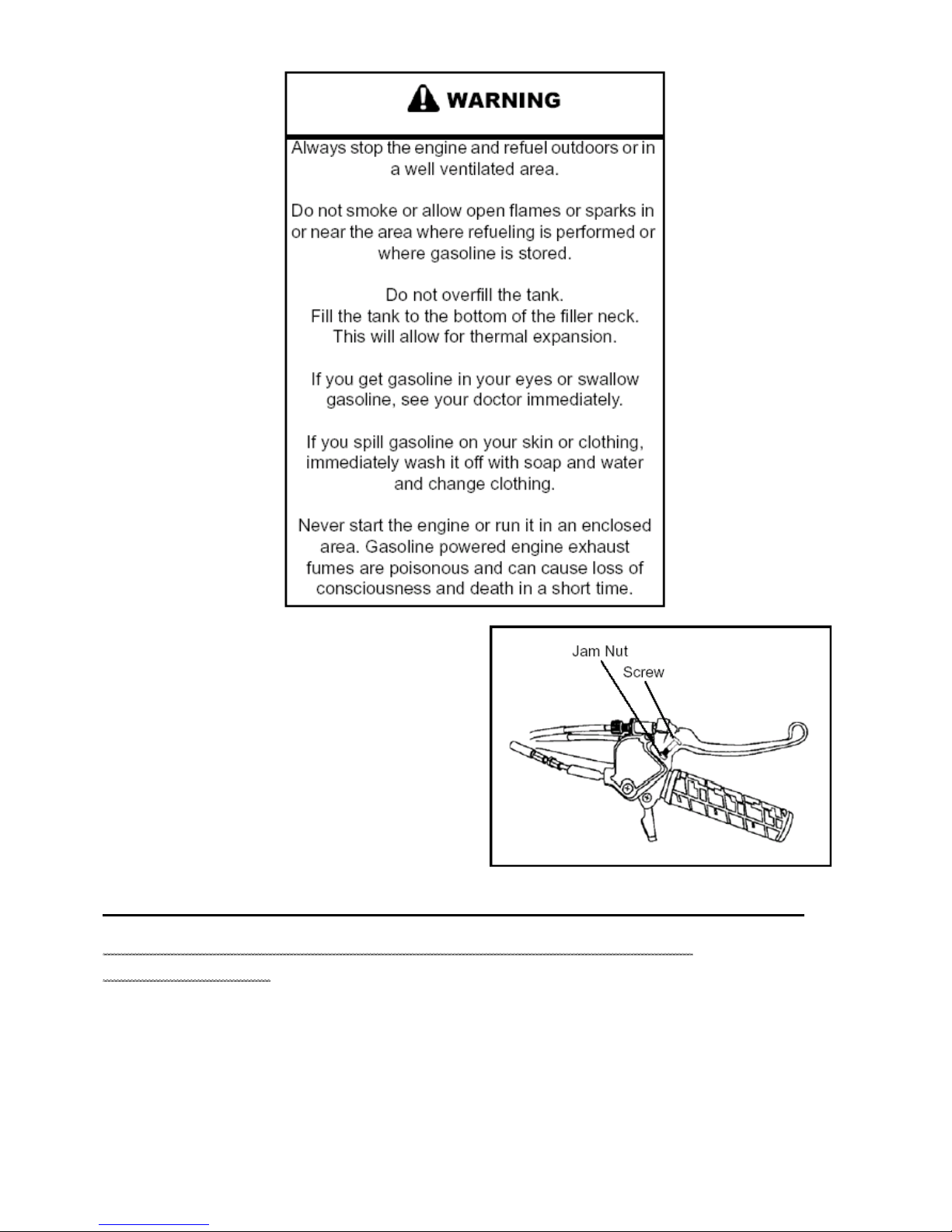
Throttle Stop Speed Control System
Use the following procedure to control how far the throttle
opens.
IMPORTANT: This procedure should be performed
by consumers only when they determine that their
child is capable of handling the additional speed.
1. Loosen the jam nut.
2. Turn the screw inward to reduce speed or outward to
increase speed.
3. Tighten the jam nut after adjusting.
2.7
MAINTENANCE
Choke Cable Adjustment
Verify free play of 1.6-4.76 mm (1/16-3/16”) and smooth
operation of choke cable.
Adjustments to the freeplay can be made by loosening the
choke cable adjustment in or out to gain the desired
freeplay.
If smooth choke operation is not obtainable, inspect choke
cable for kinks or sharp bends in routing.
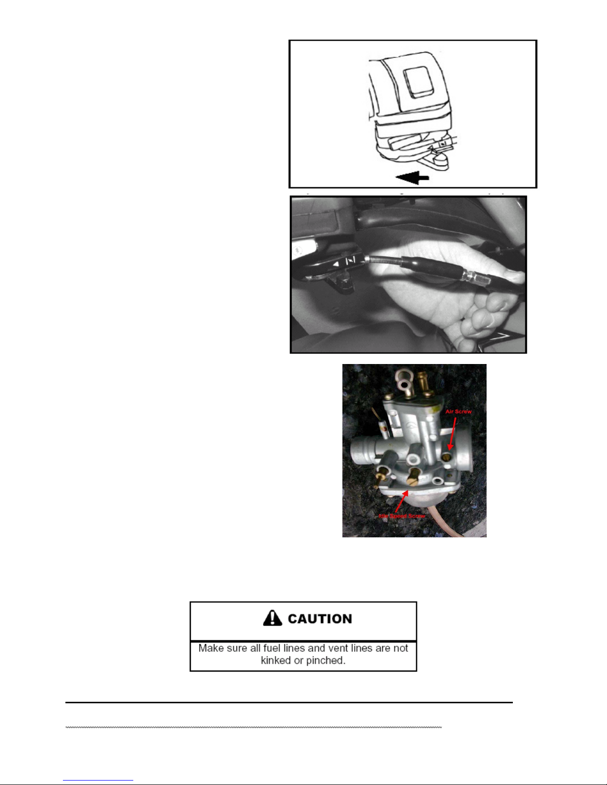
Idle Speed Adjustment
1. Start engine and warm it up thoroughly.
2. Adjust idle speed by turning the slide adjustment screw
in (clockwise) to increase or out (counterclockwise) to
decrease RPM. (Refer to illustration).
Idle Speed
1500 ± 100
Fuel Lines
1. Check fuel lines for signs of wear, deterioration, damage, or leakage. Replace if necessary.
2. Be sure fuel lines are routed properly and secured with cable ties.
3. Replace all fuel lines every two years.
2.8
MAINTENANCE
Air Screw Adjustment
1. Set idle speed to specification. Always check throttle
cable
freeplay after adjusting idle speed and adjust if necessary.
2. To adjust the mixture screw setting, you will need to use
the Adjustment Screwdriver. Slowly turn the mixture
screw clockwise until engine idle RPM begins to decrease.
Stop turning at this point.
3. Slowly turn mixture screw counterclockwise until idle
speed returns to maximum RPM. Continue turning
counterclockwise until idle RPM begins to drop. Stop
turning at this point.
4. Center the mixture screw between points in Step 2 and
3.
5. Readjust idle speed if not within specification.
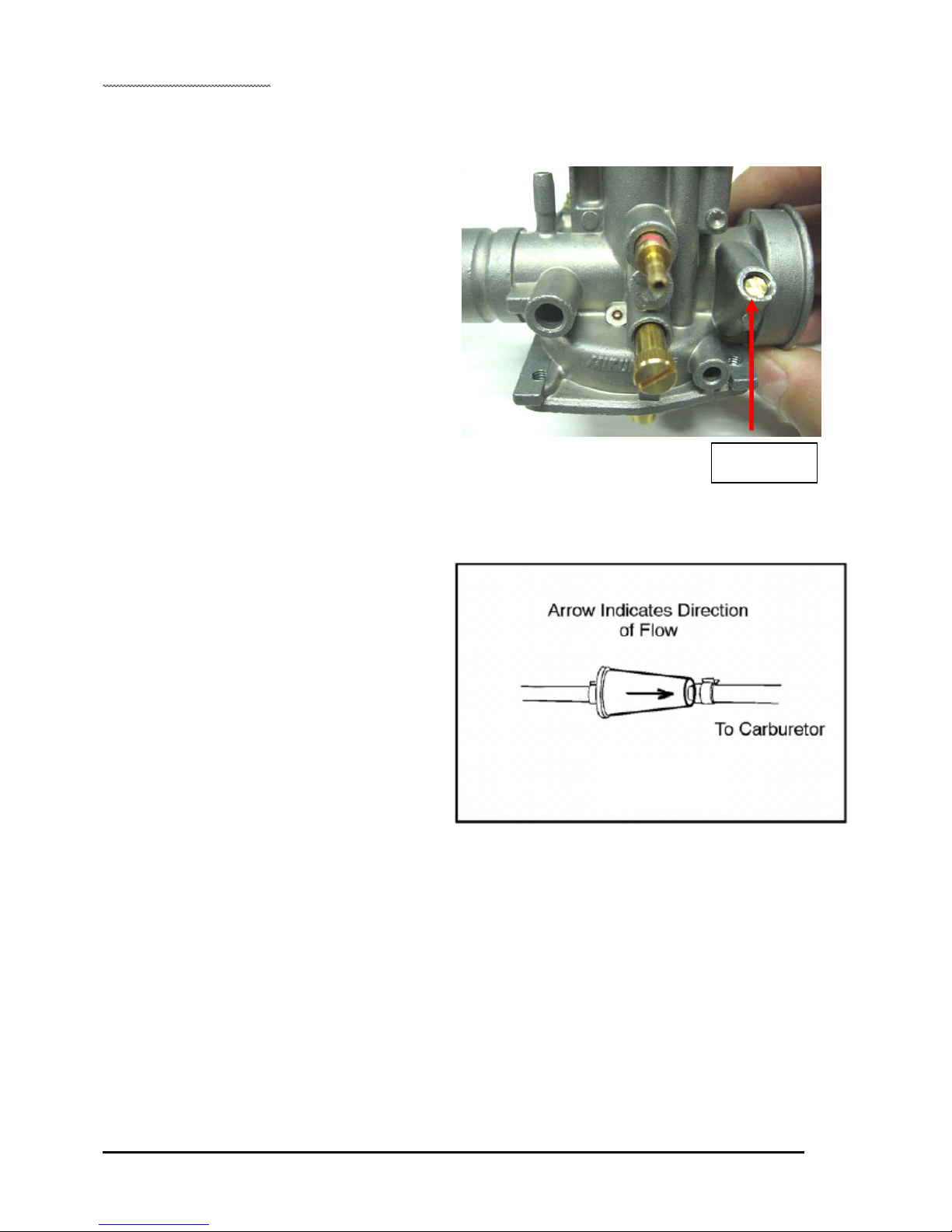
Fuel Filter
The fuel filter should be replaced in accordance with the
“Periodic Maintenance Chart” or whenever sediment is
visible
in the filter.
Fuel Filter Location - Located in-line between fuel
valve and carburetor inlet.
To service the fuel filter:
1. Shut off fuel supply at fuel valve.
2. Remove line clamps at both ends of the filter.
3. Remove fuel lines from filter.
4. Install new filter and clamps onto fuel lines.
5. Turn fuel valve to ‘ON’.
6. Start engine and inspect for leaks.
2.9
Air Screw
MAINTENANCE
Carburetor Draining
The carburetor float bowl should be drained periodically to
remove accumulated moisture or sediment from the bowl, or
before extended periods of storage.
1. Turn fuel valve to the ‘OFF’ position.
2. Place a container beneath the bowl drain hose.
3. Loosen drain screw and allow fuel in the float bowl and fuel
line to drain completely.
4. Inspect the drained fuel for water or sediment.
5. Tighten drain screw.
6. Turn fuel valve to “ON”.
7. Check for fuel leaks.
8. Start engine and re–check for leaks.

2.10
MAINTENANCE
Air Filter Service
1. Release the screw and remove the cover.
2. Remove the foam air filter. Wash the foam filter in warm
soapy water, then rinse and let it dry. If the filter is damaged,
install a new foam filter.
3. Apply a commercially available foam filter oil to the foam
filter.
4. Reinstall the screen, foam filter and air box cover. Secure
the clips.
5. The inlet pipe must toward rear of vehicle.
2.11
MAINTENANCE
ENGINE
Transmission Oil Level
Maintain the oil level within the safe range on the filler plug.
Do not overfill.
To check the oil level:
1. Position the vehicle on a level surface.
2. Remove the filler plug.
3. Check oil lever by glass widow.
NOTE: Rising oil level between checks in cool
weather driving, can indicate moisture collecting in
the oil reservoir. If the oil level is over the full mark,
change the oil.
4. Add the recommended oil as needed.
NOTE: Do not fill the over the normal oil operating
range. Filling over the normal operating range could
cause a mist of oil to enter the air box.
5. Reinstall the filler plug.
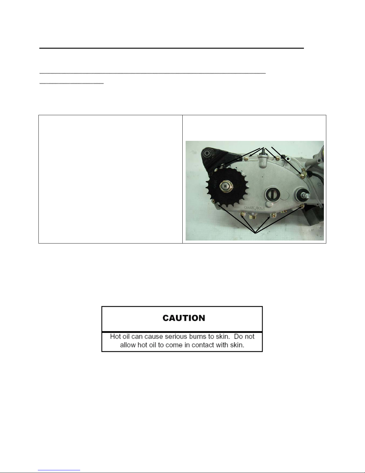
Transmission Oil Change
1. Position the vehicle on a level surface.
2. Clean area around the drain plug.
3. Run engine two to three minutes until warm.
4. Stop the engine.
5. Place a drain pan beneath the mission case.
6. Remove the drain plug. Allow the oil to drain completely.
7. Inspect the O-ring on drain plug, replace if needed.
NOTE: The sealing surfaces on the drain plug and
crankcase should be clean and free of burrs, nicks
or scratches.
11. Remove the dipstick. Add 30 oz. (900 ml) of recommended oil. Do not overfill.
12. Reinstall the filler plug.
13. Start the engine. Allow it to idle for one to two minutes.
Table of contents
Other A-EON Offroad Vehicle manuals


 owner's manual")


