A.M.Leonard AM70LP User manual

OWNER’S MANUAL
OWNER’S MANUALOWNER’S MANUAL
OWNER’S MANUAL
MODEL
MODEL MODEL
MODEL AM70LP
AM70LPAM70LP
AM70LP

1.Remove components from carton
and place spreader upside down on a
padded surface. For easier assembly,
remove the defector shield by loosening
the two wing bolts. Install LH. & RH.
handle braces to frame as shown using
four (4) 1/4-20 x 2 1/4” hex bolts and
nuts but do not tighten.
ASSEMBLY
ASSEMBLYASSEMBLY
ASSEMBLY
3.Turn spreader upright and install end of
handle tube with DOT between handle
braces as shown. Secure with (2) 1/4-20 x
1 1/2” hex bolts and nuts. Tighten bolts left
loose in Step #1.
2.Slide wheels onto end of axle with
the hub facing toward frame. Wheels are
identical to ease assembly. Align the
hole in the wheel hub and the hole in the
axle as shown. Secure drive wheel to
axle with 3/16 dia x 2” cotter pin. Insert
1/8 dia x 1 1/4” cotter pin in the hole
near the end of axle to retain free
turning wheel.
1/4-20 x 1 1/2”
Hex Bolt
1/4-20
Hex Nut
Handle
Tube
DOT
RH. Handle
Brace
LH. Handle
Brace
1/4-20 x 2 1/4”
Hex Bolt & Nut
Drive Wheel
Free Turning
Wheel
3/16 Dia x 2”
Cotter Pin
1/8 Dia x 1 1/4”
Cotter Pin
2
Deflector
Shield
S
Loosen Wing
Nuts to
remove shield

4. Feed control knob/wire through the
T-handle until spring touches the
round hole. CAUTION: Do Not
Compress Spring At This Time. Feed
wire through the square handle tube.
Be sure wire passes above the bolts in
the handle brace. Secure T-handle to
the tube with 1/4-20 x 2 1/4” hex bolts,
washers, and hex nuts as shown.
Remove caution label and push the
thumb release toward the center and
push down knob and shutoff spring
until knob latches.
CAUTION: Once knob is latched,
do not move thumb release until you have
completed in step #5.
Control Knob &
Wire Assembly
Spring
Thumb
Release
1/4-20 x 2 1/4”
Bolt & Washer
1/4-20 Hex
Nut & Washer
Remove Caution
Label
5. Slide wire retaining clip onto wire as shown.
Insert wire through hole shutoff plate. Slide
wire retaining clip over shutoff plate and wire
until the clip locks into place.
Wire Clip
Shutoff Plate
Wire
Screen Screen Clips
3
Deflector Shield
6. Install handle grips onto the handle
as shown. Soapy water will ease
installation. (Do not use petroleum
based products). Insert screen into
hopper by sliding it under the screen
clips. Install defector shield removed in
step #1.
Handle Grips

OPERATION
OPERATIONOPERATION
OPERATION
1. Check the product package for the rate
setting, and recommended swath width. Turn
the spreader OFF by pushing the control knob
in. Rotate the rate cam to the proper setting.
3. Always fill the spreader on the driveway or
sidewalk-not on the lawn. Make sure spreader is
in the “OFF” position. Empty after each use.
4. Start spreader moving, then open spreader
by pushing the thumb release to the “ON”
position. Always push spreader, never pull.
Push knob down to close spreader.
5. Hold handle so top of spreader is level. Tipping
the spreader too far can cause uneven spreading.
6. The settings and swath widths on the product
label are recommended starting points. Always
check the delivery rate and pattern on a small area
before treating a large area. Actual delivery rate
can vary due to weather conditions, operating
variables, and condition of the product being
applied. See “HOW TO DETERMINE SPREADER
SETTING AND SWATH WIDTH” for details.
7. Push spreader 2 1/2 m.p.h. (18 feet in 5
seconds) for full 8’ to 14’ spread pattern when
applying fertilizer products. Apply header strips
at each end of area to be treated then space
trips across the area as shown.
8. Empty spreader after each use. Return
leftover material to its original container.
2. The rate setting is adjusted by rotating the
rate cam to the desired setting. The rate cam
locks at each setting.
SPREAD WIDTH
APPROX.
8 to 14 FEET ON
CENTER
4
NOTE: This spreader is equipped with a factory installed deflector shield that is used for
applying ice melt to narrow areas. Shield is easily removed when ice melt is apply to large
areas or when using turf care products.

A simple visual pattern test can be
made by operating the spreader over a
non-turf area and evaluating the pattern.
A more accurate method is to place a
row of common, disposable, aluminum
cake pans approximately 1 foot on
centers. Set the rate cam at a middle
setting and make 3 or 4 passes in the
same direction as shown. Pour the
material collected from each pan into
individual bottles of the same size. Set
them side by side in order, and visually
inspect their volume. The effective
pattern width is the distance out from
the spreader to a point where the
amount of material is 1/2 the average
amount in the center pans. This
distance is multiplied by 2 to achieve
the total effective pattern width.
Knowing the effective pattern width (for example,
10 feet), measure a distance equal to 100 square
feet (10’ x 10’ area covered). Determine the
product coverage is pounds/ 100 sq. ft. by taking
the weight of the product and dividing it by the
recommended square foot coverage (add two
zeroes to the weight of the bag).
EXAMPLE: Product weight: 25 lbs.
sq. ft. coverage: 5,000 sq. ft.
2500 lbs. - 5,000 sq. ft.
= .5 lbs. / 100 sq. ft.
Weigh out between 15 to 20 lbs. of
material and spread over the 100 sq. ft.
area. Weigh remaining material left in
hopper and adjust rate setting as
required. Repeat test until application
rate is correct.
HOW TO DETERMINE SPREADER
HOW TO DETERMINE SPREADERHOW TO DETERMINE SPREADER
HOW TO DETERMINE SPREADER
SETTINGS AND SPREAD WIDTH
SETTINGS AND SPREAD WIDTHSETTINGS AND SPREAD WIDTH
SETTINGS AND SPREAD WIDTH
Two major factors should be considered when determining correct spreader settings of any
product:
1. The product application rate, or the amount of material applied per 1,000 square feet.
2. The effective pattern width, or the actual width in which material is applied. Label settings
are a guide and can be affected by numerous factors.
EFFECTIVE PATTERN WIDTH
EFFECTIVE PATTERN WIDTHEFFECTIVE PATTERN WIDTH
EFFECTIVE PATTERN WIDTH
APPLICATION RATE
APPLICATION RATEAPPLICATION RATE
APPLICATION RATE
5

RATE SETTING CONVERSION
RATE SETTING CONVERSIONRATE SETTING CONVERSION
RATE SETTING CONVERSION
The conversions should be used as guidelines for establishing proper rate settings for the particular product
being applied. Steps for obtaining the most accurate settings are outlined in the “How to Determine Spreader
Settings and Spread Width” section of this manual.
These settings are approximate and may vary due to physical characteristics of the product. Walking speed.
wear, condition of the turf and humidity, may cause actual rate setting to deviate. No expressed nor implied
warranty or guarantee is provided as to coverage or uniformity indicated by these rate settings.
AM70LP
Setting
2
3
4
5
6
7
8
9
10
11
12
13
14
15
16
17
18
Prizelawn
PrizelawnPrizelawn
Prizelawn
BF-1 /SS,HVO,
CBRlll, Setting
G
H
J
K
M
N
N1/2
O
P1/2
Q
R
S
T
U
V
X
Z
Lesco
Hi-WHEEL
Setting
E
F
G
H
I
J
K
L
—
—
M
N
O
—
P
R
S
Scott
Speedy Green
Setting
—
—
2
—
3
—
4
—
5
—
6
—
7
—
8
—
—
Scotts
R8A/SR-1,
AP&SR2000
Setting
I
J
L
M
O
P
—
Q
—
S
T
U
—
V
W
X
Z
FERTILIZER
PARTICLE SIZE BAG RATE
Pounds of fertilizer used per
1,000 sq. ft. of coverage
APPROX.
SETTING APPROX.
SPREAD
WIDTH
Large, heavy
particles
5
10
15
6
9
11
12 FT.
12 FT.
12 FT.
Medium- mixed
particles
5
10
15
5
7
9
10 FT.
10 FT.
10 FT.
Small particles
(nitrogen)
1
2
3
2
4
5
10 FT.
10 FT.
10 FT.
Mixed size particles
-some fines
5
10
15
6
9
11
8 FT.
8 FT.
8 FT.
Light weight
particles
5
10
15
4
5
6
6 FT.
To
8 FT.
The following provides approximate
AM70LP
AM70LP AM70LP
AM70LP settings for those units listed.
The following provides approximate
AM70LP
AM70LP AM70LP
AM70LP settings when only the product weight, square
foot coverage, and visual inspection of the material is available.
6

1. Never store unused material in spreader. Return
unused product to its original container.
2. Wash spreader thoroughly after each use and dry
completely in sun or heated area.
3. Oil the axle bearings, impeller shaft bearing in
hopper, control knob in T-handle.
4. Remove gear cover and wash gears thoroughly.
Oil all bearing areas and face of gear teeth. Re-
install gear cover.
5. Gear mesh should be checked on a regular basis
during high use periods. Clearance between the
axle gear and pinion gear should be minimal but not
tight. If adjustment is necessary, loosen axle collar
set screw and hold gears together. Slide axle collar
against the gear support and tighten axle collar set
screw. Spin drive wheel. Gears should run freely
and smoothly.
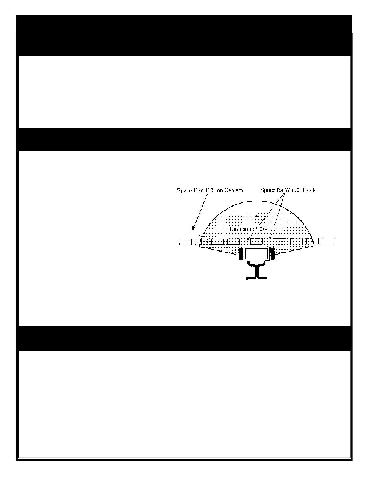
6. Impeller surface should be cleaned periodically to
remove build-up of product. Build-up can cause the
spread pattern to change.
7. Tire pressure should be 20-25 PSI.
MAINTENANCE
MAINTENANCEMAINTENANCE
MAINTENANCE
Oil
Oil Impeller Shaft
Bearing In Hopper
Axle Collar
Oil
Oil
Oil
WARRANTY
WARRANTYWARRANTY
WARRANTY
7
A.M. Leonard warrants to Purchaser the following:
1. Product will be free of defects in materials and workmanship.
2. A.M. Leonard will decide in its reasonable discretion if the part(s)/unit is defective.
3. The spreader or part(s) will be shipped to A.M. Leonard at the customer expense with a written description of defect.
4. All Unit and part replacement will be performed at the reasonable discretion of A.M. Leonard.
A.M. Leonard’s sole obligation under this warranty is limited to repairing or replacing the defective part. Upon replacement of any Product or Product part, the replacement
item shall become the property of A.M. Leonard. If A.M. Leonard determines that the Product covered by this warranty requires service, A.M. Leonard shall prepay return
shipping charges from A.M. Leonard. In all other instances, such charges shall be paid by Purchaser. Except for loss or damage caused by A.M. Leonard negligence,
Purchaser relieves A.M. Leonard of responsibility for all risks of loss or damage to the Product and its parts during the period the products are in transit to and from A.M.
Leonard .
This warranty does not extend to any Product or parts thereof that have been allowed to corrode,
subjected to misuse, neglect, accident, or modification by anyone
other than A.M. Leonard or that have been affixed to any nonstandard accessory attachment or that have been used, stored, installed, maintained or operated in violation
of A.M. Leonard’s instructions or standard industry practice. No agent, employee or representative of A.M. Leonard has any authority to bind A.M. Leonard to bind
A.M. Leonard to any affirmation, representation or warranty concerning the Product and any affirmation, representation or warranty made by any agent, employee or
representative shall not be enforceable by Purchaser.
THIS WARRANTY EXTENDS ONLY TO THE ORIGINAL PURCHASER AND IS EXPRESSLY IN LIEU OF ANY OTHER EXPRESS OR IMPLIED WARRANTIES,
INCLUDING WITHOUT LIMITATION ANY IMPLIED WARRANTY OR MERCHANTABILITY OR FITNESS OR INTENDED USE FOR A PARTICULAR PURPOSE
AND OF ANY OTHER OBLIGATION ON THE PART OF A.M. LEONARD.
A.M. LEONARD SHALL NOT BE LIABLE FOR ANY INCIDENTAL, SPECIAL OR CONSEQUENTIAL LOSS, DAMAGE OR EXPENSE DIRECTLY OR INDIRECTLY
ARISING FROM THE USE OF ANY OF THE PRODUCT INCLUDING, BUT NOT LIMITED TO, DAMAGE OR LOSS OF OTHER PROPERTY OR EQUIPMENT,
LOSS OF PROFITS OR REVENUE, COST OF CAPITAL, COST OF PURCHASED OR REPLACEMENT GOODS, OR CLAIMS OF CUSTOMERS OF PURCHASER.

1. SPREADER MODEL NUMBER
2. SPREADER NAME
3. PART NUMBER
4. NAME OF PART AS SHOWN
PARTS
PARTSPARTS
PARTS
L
LL
LIST
ISTIST
IST
FOR
FORFOR
FOR
MODEL AM70LP
MODEL AM70LPMODEL AM70LP
MODEL AM70LP
1
1A
4
2
3
5
6
11
10
12
14
8
13
7
15
16
17
7
18
19
20
21
22
23
24
9
26
Key Description Part No. Key Description Part No.
1Hopper Assembly 16581 17 Pinion Gear 14833
1A Hopper * 16582 18 Screen Clips (2) 14022
2Shutoff Plate * 14454-1 19 Hopper Screen 14603-1
3Shutoff Plate Guides (2) * 15377 20 Handle Brace W/ Plug– LH. 15852
4Rate Cam & Chute Assembly * 14455-1 21 Handle Brace W/ Plug– RH. 15853
5Impeller Assembly 15875 22 Handle Tube 15283
6Frame Assembly 15859 23 Handle Grips (2) 15264
7Drive & Free Turning Wheel 15863 24 T-Handle Assembly 13634-2
8Axle Bushings (2) 15860 25 Control Knob & Wire Ass’y. 15882
9Axle Collar 14063 26 Control Knob Spring 14462
10 Axle Gear 15027 27 Wire Retaining Clip 13643-1
11 Gear Cover Clamps (3) 14868-1 28 Hopper Plug 16583
12 Gear Cover (2) 15012 29 Agitator 14510
13 Axle 15858 30 Impeller Shaft Bearing * 14312-1
14 Impeller 14625 31 Parts Package 15864-1
15 Impeller Shaft 15856 32 Hopper Cover 14606-1
16 Gear Support—grease fitting? 15028?? 33 Deflector Shield 15464-1
25
* Parts included in Hopper Assembly
27
PART OF OUR SERVICE IS
PROVIDING REPLACEMENT
PARTS.
28
29
30
31
32
33
241 Fox Drive Piqua, OH. 45356
P.O. Box 816
1-800-543-8955
www.amleo.com
Table of contents
Other A.M.Leonard Outdoor Cart manuals