A.O. Smith BTL 100 Troubleshooting guide

Innovation has a name.
BTL 85
BTL 100
0313126 4918 - Reserved Changes.
United Kingdom & Ireland
HOT WATER STORAGE HEATERS
Installation, User and Service Manual


Preface
Copyright
Copyright © 2018 A.O. Smith Water Products
Company
All rights reserved.
Nothing from this publication may be copied,
reproduced and/or published by means of
printing, photocopying or by whatsoever means,
without the prior written approval of A.O. Smith
Water Products Company.
A.O. Smith Water Products Company reserves
the right to modify specifications in this manual.
Trademarks
Brand names in this manual are registered
trademarks of their respective owners.
Warranty
Refer to the appendix Warranty (see 12.6) for
the warranty provisions.
Liability
User
A.O. Smith accepts no liability when the water
heater is not used correctly and requires the user
to:
•Read this manual carefully and obey the
instructions.
•Ask your installation engineer for advise
about the use of the water heater.
•Make sure that the service and maintenance
activities are done by a qualified engineer.
Installation engineer
A.O. Smith accepts no liability when the water
heater is not used correctly and requires the
installation engineer to:
•Read this manual carefully and obey the
instructions.
•Make sure that the entire water heater
installation complies with the applicable
regulations (see 6).
•Make sure that the water heater is tested
before the installation is taken into use.
•Explain the correct use to the user.
•Notify the user when service and
maintenance activities are necessary.
•Make sure that you hand over all applicable
manuals.
Supplier
The BTL water heater is designed in accordance
with the applicable regulations. The water heater
is delivered with the CE-marking and all
necessary documentation to obey these
regulations.
A.O. Smith accepts no liability for claims from
third parties when:
•The instructions for the correct installation of
the water heater are not obeyed.
•The instructions for the correct use of the
water heater are not obeyed.
•The water heater did not have maintenance
on the correct maintenance interval.
For more information, refer to the General Terms
of Sales. These are available on request, free of
charge.
We believe that this manual provides you with
accurate and complete descriptions of all
relevant components. If you, nonetheless find
errors or inaccuracies in this manual, please
inform A.O. Smith. This helps us to further
improve our documentation.
Compliance
To safely produce domestic hot water, the design
and construction of the BTL water heaters is in
accordance with:
•the European Regulations 2016/426 on
appliances burning gaseous fuels (GAR).
•the European Standard for Gas–fired storage
water heaters for the production of domestic
hot water (EN89).
•The European ECO-Design Directive.
•The European Energy Labeling Directive
Refer to the appendix Declaration of conformity
(see 12.5).
Regulations
It is law that all gas appliances are installed by
competent persons, in accordance with The Gas
Safety (Installation and Use) Regulations 1998.
Failure to install appliances correctly could lead
to prosecution. It is in your own interest, and
that of safety, to ensure that this law is complied
0313126_BTL_UKUK_V1.1, 30-11-2018 3

with. The installation of the equipment MUST be
in accordance with the relevant requirements of
the Gas Safety Regulations, Building Regulations,
I.E.E. Regulations and the bylaws of the local
water undertaking.
In addition, the installation should follow the
relevant guidance offered in the following
documents. It is not practical to list all relevant
information due to continuous changes but
emphasis is placed on the following documents,
as failure to comply with the guidance given will
almost certainly result in an unsatisfactory
installation:
•British Standards (BS)
•Institute of Gas Engineers and Managers
(IGEM) Publications
•CIBSE Guides
•Clean Air Act
•H.S.E Guidance
Note
Manufacturer's notes must not be taken in any
way as overriding statutory obligations.
Contact information
If you have any comments or questions, please
contact:
A.O. Smith Water Products Company
Adress: PO Box 70
5500 AB Veldhoven
The Netherlands
Telephone: 0870 - AOSMITH (free)
0870 - 267 64 84
General: +31 40 294 25 00
Fax: +31 40 294 25 39
E-mail: [email protected]
Website: www.aosmith.co.uk
In the event of problems with your gas,
electricity or water supply connections, please
contact your supplier.
About this manual
Scope
This manual gives information about safe and
correct use of the water heater and how
installation, maintenance and service activities
have to be done correctly. You must obey the
instructions in this manual.
n
Caution
Read this manual carefully before you start the
water heater. It can cause personal injury and
damage to the water heater when you do not
read the manual and/or do not obey the
instructions.
The purpose of this manual is to:
•describe the working principles and layout of
the water heater
•explain the safety devices
•highlight possible hazards
•describe the use of the water heater
•describe the installation, service and
maintenance of the water heater
This manual has two parts:
•An User part that describes the correct usage
of the water heater.
•An Installation, Maintenance and Service
part, that describes the correct installation
and maintenance procedures.
Target group
The information in this manual applies to three
target groups:
•users
•installation engineers
•service and maintenance engineers
The User part is intended for the (end) users.
The Installation, Maintenance and Service part is
intended for the installation engineers and the
service and maintenance engineers.
Notation conventions
This manual uses the following text conventions:
•Numbers between parentheses e.g. (1), refer
to elements in a figure that are described by
the text.
•Knobs or symbols on the knobs are always
shown between brackets, for example:
[], [ ], [ ].
•Cross-references to sections, tables, figures
etc. are underlined and written as (see "...").
In the digital version, the cross-references
function as hyperlinks that can be used to
navigate through the manual by clicking on
them. Example: Safety (see 2).
This manual contains the following text styles/
symbols for situations that may endanger users/
c
4

engineers, cause damage to equipment or need
special attention:
Note
A note gives more information on a topic.
Caution
Obey the caution instructions to prevent
damage of the water heater.
Warning
Obey the warning instructions to prevent
danger of personal injury, and serious damage
to the water heater.
Danger
Obey the danger instructions to prevent danger
of serious personal injuries or death, and
serious damage to the water heater.
Document identification
Article
number
Language Version
0313126 EN 1.0
Table of Contents
Preface....................................3
Copyright......................................... 3
Trademarks...................................... 3
Warranty..........................................3
Liability............................................3
Compliance...................................... 3
Regulations...................................... 3
Contact information...........................4
About this manual................... 4
Scope.............................................. 4
Target group.....................................4
Notation conventions......................... 4
Document identification..................... 5
User part................................. 6
1 Introduction............................6
2 Safety..................................... 6
3 Operation................................ 7
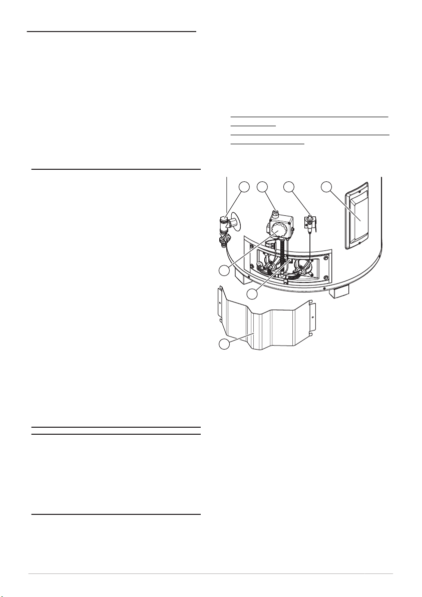
3.1 Control components.......................... 7
n
c
w
d
3.1.1 Operation control knob.......................7
3.1.2 Temperature control knob...................8
3.2 Status of the water heater..................8
3.2.1 Operating modes...............................8
4 Use..........................................8
4.1 Turn on the water heater....................8
4.1.1 Temperature setting.......................... 9
4.2 Turn off the water heater....................9
4.2.1 Turn off for a short period...................9
4.2.2 Turn off for a long period....................9
Installation, Maintenance and
Service part.............................9
5 Introduction............................9
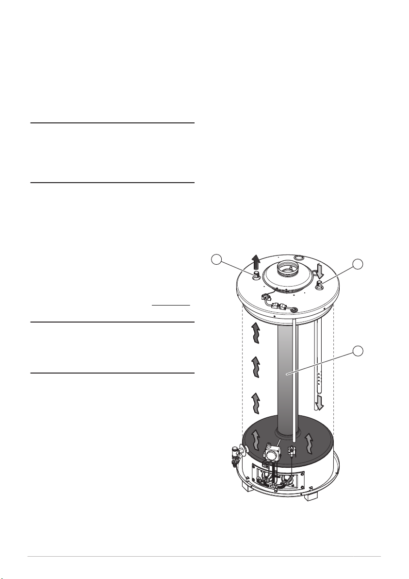
5.1 About the water heater...................... 9
5.2 Working principle.............................. 9
6 Safety................................... 10
6.1 Safety instructions...........................10
6.2 Instructions on the water heater........10
6.3 Safety devices................................ 11
6.4 Environmental aspects..................... 11
6.4.1 Recycling........................................11
6.4.2 Disposal......................................... 11
7 Water heater.........................12
7.1 Structure of the water heater............ 12
8 Installation........................... 13
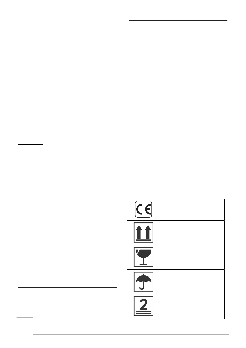
8.1 Packaging.......................................13
8.2 Conditions...................................... 13
8.2.1 Ambient conditions.......................... 13
8.2.2 Maximum floor load......................... 13
8.2.3 Water composition........................... 13
8.2.4 Working clearances..........................13
8.2.5 Placement of the water heater...........14
8.3 Installation diagram.........................14
8.4 Water connections........................... 14
8.4.1 Cold water connection......................14
8.4.2 Hot water connection....................... 14
8.4.3 Circulation connection...................... 14
8.4.4 Drain valve..................................... 15
8.5 Gas connection............................... 15
8.6 Flue gas discharge...........................15
8.6.1 Draught diverter..............................15
8.6.2 T.R.S. (Thermal Reflux Safeguard)..... 15
8.6.3 Discharge pipe................................ 16
8.7 Commissioning................................16
8.7.1 Filling............................................ 16
8.7.2 Burner pressure.............................. 16
8.7.3 Turn on the water heater.................. 17
8.8 Decommisioning..............................17
8.8.1 Turn off the water heater..................17
8.8.2 Draining......................................... 17
0313126_BTL_UKUK_V1.1, 30-11-2018 5

9 Conversion of gas type..........17
10 Maintenance..........................17
10.1 Performance check.......................... 18
10.2 Water-side maintenance................... 18
10.2.1 Inspect the anode............................18
10.2.2 Inspect the inlet security group......... 18
10.2.3 Descale the tank............................. 19
10.3 Gas-side maintenance......................19
10.3.1 Clean the burners............................19
10.3.2 Clean the combustion chamber..........20
10.3.3 Assemble the burners...................... 20
10.3.4 Finalization..................................... 20
11 Troubleshooting.................... 20
11.1 General..........................................20
11.1.1 Safety thermostat........................... 20
11.1.2 T.R.S. (Thermal Reflux Safeguard)..... 20
11.1.3 Condensation..................................21
11.2 General errors.................................22
12 Appendices............................23
12.1 Technical details.............................. 23
12.2 Dimensions.....................................24
12.3 EcoDesign details............................ 25
12.4 Gas details..................................... 27
12.5 Declaration of conformity..................29
12.6 Warranty........................................ 30
1 Introduction
The BTL water heater stores and heats water for
sanitary purposes.
Cold water enters the tank (3) through the water
inlet (2). The heated water leaves the tank at the
top through the hot water outlet (1). When hot
water is used, the tank of the water heater is
filled with the same amount of cold water.
To operate the water heater, the control knobs on
the gas control valve (5) are used.
Fig. BTL water heater
1 2
5
4
3
1. Water outlet
2. Water inlet
3. Tank
4. Outer door
5. Gas control valve
2 Safety
A.O. Smith cannot be held responsible for
damages or injuries which can be lead back to:
•Failure to follow the instructions provided in
this manual.
•Carelessness during use or maintenance of
the water heater.
Every user must study the user part of this
manual and must follow the instructions in this
part of the manual strictly. Do not change the
sequence of the described actions. This manual
must be available for the user and service
engineer at all times.
Warning
w
6 User part

If you smell gas:
- Shut off the mains gas supply valve!
- Avoid causing sparks! Do not use any
electrical equipment or switch, i.e. no
telephones, plugs or bells!
- No naked flames! No smoking!
- Open windows and doors!
- Warn occupants and leave the building!
- After leaving the building, alert the gas
distribution company or your installation
engineer.
Caution
Do not store or use chemical substances in the
room where the water heater is installed
because of the risk of explosion and corrosion
of the water heater. Some propellants,
bleaching agents and degreasing agents etc.
disperse of explosive vapors and/or cause
accelerated corrosion. If the water heater is
used in a room where such substances are
stored or used, the warranty will be void.
Caution
Installation, maintenance and service may only
by carried out by a qualified engineer.
Caution
The water heater is not intended for use by
persons with reduced physical, sensory or
mental capacities, or who lack the necessary
experience or knowledge. When the person
responsible for their safety is supervising or has
explained how the water heater should be
used, these persons can use the water heater.
Caution
This water heater is not intended to be used by
children. Always supervise children, and make
sure that they do not play with the water
heater.
Note
Regular maintenance extends the service life of
the water heater. To determine the correct
service interval, the service and maintenance
engineer must do a check on both the water
and gas side of the water heater three months
after installation. Based on this check, the best
service interval can be determined.
c
n
3 Operation
3.1 Control components
For the use of the BTL water heater, the gas
control valve has two control knobs:
•The operation control knob on top of the gas
control valve (see 3.1.1).
•The temperature control knob on the front of
the gas control valve (see 3.1.2).
Fig. Control components
1
3
2
4 6 75
1. Outer door
2. Pilot flame inspection window
3. Temperature control knob
4. Drain valve
5. Operation control knob
6. Piezo igniter
7. Cleaning opening
3.1.1 Operation control knob
You can use the operation control knob to
activate and to deactivate the water heater. The
symbols on the operation control knob indicate
the 3 possible settings.
0313126_BTL_UKUK_V1.1, 30-11-2018 7
wWarning

Symbol Explanation
Water heater is activated, the
pilot flame burns (frost
protection).
In this setting, you can put the
water heater in the OFF mode
or in the ON mode with the
temperature control knob.
In this setting, you can ignite
the pilot flame to turn on the
water heater (no frost
protection).
Water heater is OFF, pilot
flame does not burn (no frost
protection).
3.1.2 Temperature control
knob
With the temperature control knob you can set
the desired water temperature of the water
heater (see 4.1.1).
When the operation control knob is in the
position [ ], you can use the temperature
control knob to set the water heater in the OFF
mode or in the ON mode:
•Turn the temperature control knob
anticlockwise to ignite the main burners (ON
mode).
•Turn the temperature control knob clockwise
to shutdown the main burners. Only the pilot
flame burns (OFF mode).
3.2 Status of the water
heater
During operation, the operation control knob
shows the status of the water heater
.
3.2.1 Operating modes
The BTL has 2 operating modes:
•OFF mode (see 3.2.1.1)
•ON mode
3.2.1.1 OFF mode
In the OFF mode the water heater is de-
activated. The operation control knob is set in
the position [] and the temperature control
knob is completely turned clockwise. The pilot
flame in activated.
To prevent that the water in the system freezes,
the frost protection is activated when the water
heater is in OFF mode. The frost protection
starts when the temperature of the water drops
below 5 ºC. The water heater will heat the water
to 20 ºC and then turns back to the OFF mode.
3.2.1.2 ON mode
In the ON mode the water heater continuously
responds to the heat demand. The operation
control knob is set in the position [] and the
temperature control knob is turned to one of the
5 positions. The pilot flame is activated and
ignites the main burners when there is a heat
demand.
4 Use
4.1 Turn on the water
heater
Caution
Make sure that the water heater is filled with
water before you turn on the water heater.
To start the water heater:
1. Remove the outer door (see 3).
2. Open the gas supply.
3. Turn the temperature control knob
completely clockwise.
4. Turn the operation control knob to [ ].
5. Push the operation control knob and
simultaneously push the Piezo igniter button
several times until the pilot flame burns.
Note
When the pilot flame burns, hold the operation
control knob for approximately 20 seconds.
6. Release the operation control knob.
7. Look through the pilot flame inspection
window to make sure that the pilot flame
remains on.
Note
When the pilot flame extinguishes, wait for at
least 5 minutes and repeat this procedure from
step 5.
8. Turn the operation control knob to [ ].
9. Turn the temperature control knob to the
desired Temperature setting (see 4.1.1).
10. Replace the outer door.
c
n
n
8 User part

4.1.1 Temperature setting
Use the temperature control knob to set the
temperature:
•Position 1 = approximately 40°C
•Position 2 = approximately 50°C
•Position 3 = approximately 60°C
•Position 4 = approximately 70°C
•Position 5 = approximately 80°C
Caution
Preferably turn the temperature control knob in
position 3. Harmful scaling and lime build-up
will be higher when using position 5. At lower
temperature settings there is a higher risk of
high legionella concentrations in the water.
When the water temperature reaches 90 °C, the
safety thermostat cuts off the gas supply
completely and the pilot flame goes out.
4.2 Turn off the water
heater
4.2.1 Turn off for a short
period
To turn off the water heater for less than 2
months, set the water heater in the OFF mode
(see 3.2.1.1).
Note
If the water heater stays in the OFF mode for
more than 2 months and no water is drained,
air bubbles may be formed in the water heater.
This can lead to air in the water pipes.
4.2.2 Turn off for a long period
When the water heater needs to be turned off for
more than 2 months, contact your service and
maintenance engineer to decommission the
water heater
.
5 Introduction
5.1 About the water heater
The BTL water heater is intended for heating
water for sanitary purposes.
The BTL is a gas–fired storage water heater. The
flue gasses transfer their heat to the water
c
n
through an heat exchanger. The water heater has
an open flue gas discharge connection.
5.2 Working principle
Cold water enters the tank through the water
inlet (1). When the water temperature drops
beneath the set temperature, the gas supply to
the main burners is opened automatically and
the water is heated. A heat exchanger (3)
transfers the heat from the flue gasses to the
water and the hot water leaves the tank through
the water outlet (2).
The tank of the water heater has to be
completely filled during operation. The tank at
least must remain under mains water supply
pressure at any time. Fresh cold water is
immediately added when hot water is drawn
from the water heater. A temperature sensor
measures the water temperature.
Fig. BTL water heater
12
3
1. Water outlet
2. Water inlet
3. Heat exchanger
0313126_BTL_UKUK_V1.1, 30-11-2018 9

6 Safety
6.1 Safety instructions
For safety instructions on the use of the water
heater, refer to Safety (see 2) in the User part of
this manual.
Warning
Installation, maintenance and service must be
carried out by a qualified engineer in
compliance with the general and local
regulations imposed by the gas and water
supply companies and the fire brigade. The
appliance may only be installed in a room that
complies with the requirements stated in
national and local ventilation regulations (see
6).
Warning
This appliance must be installed on a non-
flammable floor or surface.
Caution
The water heater may only be moved in an
upright position. After unpacking, make sure
that the water heater is not damaged.
Caution
Use of an incorrect roof flue terminal can cause
the water heater to malfunction.
Caution
Make sure that the diameter of the gas supply
pipe is large enough to supply sufficient
capacity to the water heater.
Caution
Fill the water heater completely before use. Dry
firing will damage the water heater.
Caution
After installation or maintenance, always check
that the appliance is gas tight and make sure
that the gas supply pressure and the burner
pressure are correct.
If the gas supply pressure is not correct,
contact your mains gas supply company. Do
not use the water heater.
Danger
Never deactivate the T.R.S.. Backdraft of flue
gas can lead to a dangerous situation.
w
c
d
Note
Any leakage from the tank and/or connections
can cause damage to the immediate
environment or floors below the level of the
boiler room. Install the water heater above a
waste water drain or in a suitable metal leak
tray.
The leak tray must have an appropriate waste
water drain and must be at least 5 cm deep
with a length and width of at least 5 cm larger
than the water heater.
6.2 Instructions on the
water heater
The water heater has some safety instructions on
its cover:
•The text "Read the installation instructions
before installing the appliance".
•The text "Read the user instructions before
putting the appliance into operation".
Also the packaging has some safety instructions:
•The text "Read the installation instructions
before installing the appliance".
•The text "Read the user instructions before
putting the appliance into operation".
•The text "The appliance may only be installed
in a room that meets the required ventilation
regulations".
•Some safety pictograms:
CE approved
This way up
Fragile
Keep dry
Maximum stacking height is 2
n
10 Installation, Maintenance and Service part

6.3 Safety devices
Safety devices of the water heater:
Gas control valve The gas control valve controls the gas supply to the
burners and to the pilot burner.
Thermocouple The thermocouple detects the presence of a pilot flame.
When the pilot flame extinguishes, the gas supply is
closed.
T.R.S.
Thermal Reflux Safeguard
The T.R.S. detects the presence of returning flue gases on
the draught diverter. The T.R.S. detects an increase of
temperature in the edge of the draft diverter. When the
temperature becomes too high, the gas supply is closed.
Safety devices of the installation:
Inlet security group The inlet security group is the combination of the stop
valve, a non return valve and a pressure relief valve. The
inlet security group prevents excessive pressure in the
tank and back flow of expansion water into the cold water
main supply.
Pressure-reducing valve The pressure-reducing valve reduces the water mains
pressure, if necessary.
T&P valve
Temperature and pressure
relief valve (1)
The T&P valve is a temperature and pressure relief valve
which is activated when:
- the temperature exceeds 97°C.
- the pressure exceeds 7 bar.
1- All appliances have a T&P valve connection. A.O. Smith recommends to use a T&P valve.
6.4 Environmental aspects
6.4.1 Recycling
The packaging material is environmentally
friendly, recyclable and relatively easy to discard.
6.4.2 Disposal
Old end-of-life appliances contain materials that
need to be recycled. When you discard devices at
the end of their service life, you must obey local
legislation related to waste disposal.
Never discard your old device together with
regular waste. Put the device into a municipal
waste collection depot for electrical and
electronic equipment. If necessary, ask your
supplier or your service and maintenance
engineer for advice.
0313126_BTL_UKUK_V1.1, 30-11-2018 11

7 Water heater
7.1 Structure of the water
heater
The water heater has the following main
components:
Tank The water is stored and
heated up in the tank.
Burners The burners (with a pilot
flame) ignite the air and gas
mixture to heat up the water.
Gas control
valve
The gas control valve controls
the gas supply to the burners.
Fig. Components water heater
8
6
7
6
1
9
10
11
12
13
14
16
15
2
4
3
5
1 Draught diverter
2 T.R.S. sensor
3 T.R.S. thermostat
4. Tank
5 Burner tube
6 Interrupter thermocouple
7 Drain valve
8 Gas control valve
9 Flue baffle
10 Heat exchanger
11 Combustion chamber
12 Burners
13 Thermocouple
14 Pilot pipe
15 Igniter
16 Pilot burner
12 Installation, Maintenance and Service part

8 Installation
Warning
The installation must be done by a qualified
person, in compliance with general and local
applicable regulations (see 6).
Caution
The water heater may not be used in rooms
where chemical substances are stored or used
because of the risk of explosion and corrosion
of the water heater
. Some propellants,
bleaching agents and degreasing agents etc.
disperse of explosive vapors and/or cause
accelerated corrosion. If the water heater is
used in a room where such substances are
stored or used, the warranty will be void.
For more safety instructions, refer to Safety
instructions (see 6.1).
8.1 Packaging
A.O. Smith recommends to unpack the water
heater at or near its intended location. Remove
the packaging material carefully to prevent
damage to the water heater.
8.2 Conditions
The water heater must be installed in a location
with adequate ventilation and a suitable flue gas
discharge.
8.2.1 Ambient conditions
The installation site must be frost-free. If
necessary, adjust the installation site to keep it
frost-free.
Air humidity and ambient temperature
Air humidity Max. 93% RH
at + 25 ºC
Ambient
temperature
Functionality:
0 < T < 40 ºC
8.2.2 Maximum floor load
Refer to the building construction engineer and
the general specifications in the appendices (see
12) to make sure that the maximum floor load is
sufficient for the weight of the water heater.
w
c
8.2.3 Water composition
The water must comply with the regulations for
drinking water for human consumption.
Water composition
Hardness
(alkaline earth
ions)
> 1.00 mmol/l:
- German hardness
>5.6° dH
- French hardness
> 10.0° fH
- English hardness
> 7.0° eH
- CaCO3 > 100 mg/l
Conductivity > 125 µS/cm
Acidity (pH
value)
7.0 < pH value < 9.5
Note
If the water specifications differ from the
specifications in the table, the tank protection
cannot be guaranteed, refer to Warranty (see
3).
8.2.4 Working clearances
Make sure that there is sufficient clearance to
access the water heater:
•50 cm in front of the water heater (AA).
•50 cm at the left and right side of the water
heater (BB).
•100 cm at the top of the water heater.
Fig. Working clearances
IMD-1333 R0
A
A
AA
BB
n
0313126_BTL_UKUK_V1.1, 30-11-2018 13

8.2.5 Placement of the water
heater
Before you install the water connections and gas
connections, place the water heater on the
correct position and make sure that the water
heater is level.
C
B
D
9
10
4
14 14 14
6
5
4
3
11
IMD-1331 R0
16
A
4
1
5
15
12
T
1. Pressure reducing valve
(mandatory if the mains water pressure is too high)
3. T&P valve (optional)
4. Stop valve (recommended)
5. Non-return valve
6. Circulation pump (optional)
9. Drain valve
10. Manual gas valve
11. Service stop valve
12. Temperature gauge (optional)
14. Draw-off point
15. Expansion valve
16. Expansion vessel
A. Cold water supply
B. Hot water outlet
C. Circulation pipe (optional)
D. Gas supply
Use this installation diagram when
you:
- install the water connections
(see 8.4)
- install the gas connection (see
8.5)
- fill the water heater (see
8.7.1)
- drain the water heater (see
8.8)
8.4 Water connections
8.4.1 Cold water connection
Install the cold water connection:
1. Install an approved stop valve (4), as
required by the applicable regulations (see
6).
2. Install an approved pressure reducing valve
(1) to prevent that the pressure in the cold
water supply pipe exceeds the maximum
working pressure of the tank, 8 bar
. Refer to
the Technical details.
3. Install a non-return valve (5).
4. Install an expansion valve (15).
5. Connect the overflow connection of the
expansion valve, to an open waste water
pipe.
6. Install an expansion vessel (16).
8.4.2 Hot water connection
Note
Insulate long hot water pipes to prevent
unnecessary energy loss.
Install the hot water connection:
1. Install a stop valve (11) in the hot water
outlet pipe for service reasons.
2. If applicable, install a temperature gauge
(12).
3. Install a T&P valve (3).
8.4.3 Circulation connection
Install a circulation system when an immediate
flow of hot water at draw-off points is required.
This improves comfort and reduces water
wastage.
n
14 Installation, Maintenance and Service part
8.3 Installation diagram
Fig. Installation diagram
Warning
This appliance must be installed on a non-
flammable floor or surface.
w

Note
Use the drain valve connection (9) as a
connection of the circulation pipe on the water
heater.
Note
Make sure that the circulation pump has the
correct capacity for the length and resistance of
the circulation system.
Install a circulation pump:
1. Install a circulation pump (6).
2. Install a non-return valve (5) after the
circulation pump to make sure that the
direction of circulation is guaranteed.
3. Install a stop valve (4) before the circulation
pump.
4. Install a stop valve (4) after the non-return
valve.
5. Connect the circulation pipe to the drain
valve (9).
8.4.4 Drain valve
Install the drain valve:
1. Fasten the drain valve (9) in the connection
in the front of the water heater.
2. Place the cap over the connection to make it
watertight.
8.5 Gas connection
Caution
Make sure that the gas supply pipe has the
correct diameter and length to supply sufficient
capacity to the water heater.
Caution
Make sure that the gas supply pipe is clean.
Contamination in the pipe can cause damage to
the gas control valve, during operation.
Caution
Install the manual gas valve on a spot
accessible for the user.
Install the gas connection:
1. Install the manual gas valve (10) in the gas
supply pipe.
2. Make sure that the gas pipe is clean before
use. If necessary, remove the contamination
from the pipe.
3. Close the manual gas valve.
n
c
4. Install the gas supply pipe to the gas control
valve.
5. Make sure that there are no gas leaks.
8.6 Flue gas discharge
Caution
It is not allowed to make changes to the flue
gas discharge or to apply casings on it.
Install the flue gas discharge:
1. Install the draught diverter on top of the
water heater. (see 8.6.1)
2. Install the T.R.S.
3. Install the discharge pipe. (see 8.6.3)
8.6.1 Draught diverter
Install the delivered draught diverter on top of
the water heater.
For correct installation of the draught diverter,
please refer to the installation instructions
delivered with the draught diverter.
Fig. Install the draught diverter
8.6.2 T.R.S. (Thermal Reflux
Safeguard)
The T.R.S. (Thermal Reflux Safeguard) is
installed on the draught diverter.
Note
Make sure that the temperature probe is
positioned at the front side of the water heater.
If necessary, reinstall the draught diverter.
To install the T.R.S.:
1. Remove the screws from the bracket.
c
n
0313126_BTL_UKUK_V1.1, 30-11-2018 15

2. Use the screws to install the bracket on the
water heater.
3. If necessary, use the screws to install the
T.R.S. thermostat in the bracket.
4. Connect the plug of the T.R.S. thermostat.
Caution
Make sure that the T.R.S. sensor does not have
sharp kinks. This can lead to malfunctions
which can damage the equipment.
Fig. Install the T.R.S. thermostat
8.6.3 Discharge pipe
Install a vertical discharge pipe directly on top of
the draught diverter. This pipe must have at least
50 cm of length before the first bent.
Note
Make sure that the discharge pipe is protected
against corrosion and has at least the same
diameter of the draught diverter.
8.7 Commissioning
To commission the water heater:
1. Fill the water heater (see 8.7.1)
2. Check the burner pressure (see 8.7.2)
3. Turn on the water heater (see 8.7.3)
8.7.1 Filling
Refer to the installation diagram (see 8.3) when
you fill the water heater:
1. Open the stop valve (11) in the hot water
supply pipe.
2. If applicable, open the stop valves (4) of the
circulation pipe (C).
c
n
3. Make sure that the drain valve (9) is closed.
4. Open all hot water draw-off points (14) to
bleed the entire installation of air.
5. Open the valve of the inlet security group (2)
in the cold water supply pipe (A). Cold water
flows into the water heater.
6. Fill the water heater until cold water flows out
of all opened draw-off points. The water
heater is completely full.
7. Make sure that no water comes out of the
pressure relief valve of the inlet security
group (2) or the T&P valve (3). If water
comes out:
- Examine if the water supply pressure is
greater than the specified value in the
Technical details. If necessary, install a
pressure reducing valve (1).
- Examine if the pressure relief valve of the
inlet security group in the protected cold
supply set-up is installed correctly and is
not defect. If necessary, replace the
expansion valve.
8. Close all hot water draw-off points.
8.7.2 Burner pressure
Make sure that the burner pressure is set
correctly in order to check the nominal load.
Check the burner pressure:
1. Remove the sealing screw of the test nipple.
2. Connect a pressure gauge to the test nipple
as soon as you smell gas.
3. Turn on the water heater (see 4.1).
4. If necessary, create a heat demand:
- Use a hot water draw-off point to tap
water, or
- Use the temperature control knob to raise
the setpoint of the water temperature
(see 4.1.1).
5. Wait about 1 minute.
6. Use the pressure gauge to read the burner
pressure and compare it with the value from
the appendix Gas details (see 12.4).
7. If necessary, correct the burner pressure with
the pressure adjustment screw:
a) Remove the temperature control knob by
pulling it straight out. The burner
pressure adjustment screw ("pr adj") will
be visible.
b) Turn the screw anticlockwise to decrease
the burner pressure or clockwise to
increase the burner pressure.
c) Replace the temperature control knob.
8. Turn the water heater off (see 4.2).
9. Disconnect the pressure gauge.
10. Replace the sealing screw and tighten it on
the test nipple.
16 Installation, Maintenance and Service part

Fig. Set nominal load of the gas burners
8.7.3 Turn on the water heater
Refer to the procedure in the user part to Turn
on the water heater (see 4.1).
8.8 Decommisioning
To decommission the water heater:
1. Turn off the water heater (see 8.8.1)
2. Drain the water heater (see 8.8.2)
8.8.1 Turn off the water heater
Refer to the procedure in the user part to Turn
off the water heater (see 4.2).
8.8.2 Draining
Refer to the installation diagram (see 8.3) when
you drain the water heater:
1. Close the manual gas valve (10).
2. If applicable, close the service stop valve
(11) in the hot water pipe.
3. Close the stop valve (10).
4. Open the drain valve (9).
5. Aerate the entire installation of air until the
water heater is completely drained.
Note
Disconnect and tilt the water heater in the
direction of the drain valve when the water
heater needs to be drained completely.
9 Conversion of gas
type
Caution
Conversion of the water heater may only be
carried out by a qualified person.
Use a conversion kit to convert the water heater
when the water heater has to operate on a gas
n
c
category other than that for which the water
heater has been configured at the factory.
You can order the conversion kit you need from
the supplier of your water heater. The conversion
kit contains all the parts needed to do the
conversion and an instruction how to do the
conversion.
The following conversions are possible:
•Conversion from natural gas to LPG.
•Conversion from LPG to natural gas.
•Conversion from natural gas to natural gas.
Caution
After the conversion, make sure that the water
heater is gas-tight. Make sure that the supply
pressure and the burner pressure have the
correct value.
10 Maintenance
The water heater needs maintenance at least
once a year. The maintenance interval is
determined by the water quality, the average
burning time each day and the set water
temperature.
To determine the correct interval, A.O. Smith
recommends to do a system check on both the
water and the gas side, three months after
installation.
Note
Do maintenance to maintain an effective and
efficient transfer of heat to the water. This
significantly increases the service life of the
water heater.
Note
When needed, spare parts can be ordered. To
be sure that you receive the correct spare
parts, look at the data plate for the full serial
number, the water heater model, and the used
gas category. Use this information when you
order the spare parts.
Do the following maintenance activities:
•Performance check (see 10.1)
•Water-side maintenance (see 10.2)
•Gas-side maintenance (see 10.3)
c
n
0313126_BTL_UKUK_V1.1, 30-11-2018 17

10.1 Performance check
Check if the performance of all components is
correct:
1. Make sure that the water heater operates the
operating cycle correctly.
2. Make sure that the color of the flame is blue.
3. If applicable, make sure that the T&P valve
operates correctly.
Open the T&P valve pressure relief and make
sure that water spurt out.
Warning
Hot water can come out of the T&P valve.
4. Make sure the pressure relief connection of
the inlet security group operates correctly.
Open this pressure relief and make sure that
water spurt out.
5. Make sure the pressure of the gas supply is
correct:
a) Remove the sealing screw of the test
nipple under the gas supply connection.
b) Connect a pressure gauge to the test
nipple as soon as you smell gas.
c) Use the pressure gauge to read the gas
supply pressure and compare it with the
value from the appendix Gas details (see
12.4).
d) Disconnect the pressure gauge.
e) Replace the sealing screw and tighten it
on the test nipple.
6. Make sure the burner pressure is correct (see
8.7.2).
10.2 Water-side
maintenance
To do water side maintenance:
•Inspect the anode (see 10.2.1)
•Inspect the inlet security group (see 10.2.2)
•Descale the tank (see 10.2.3)
10.2.1 Inspect the anode
The life cycle of the anode is determined by the
quality and the quantity of the water that flows
through the water heater. Inspect the anode at
least once a year to make sure that the tank is
protected against corrosion.
To inspect the anode:
1. Close the pressure reducing valve in the cold
water supply.
2. Open the nearest hot water tap to reduce the
water pressure in the water heater
.
w
3. Use a wrench to loosen the anode.
4. Take the anode out of the water heater.
5. Inspect the volume of the anode. When the
anode is consumed for 60 % or more, replace
the anode.
Note
If the anode needs to be replaced, always use
an anode of the same type. Please refer to the
type and the serial number on the data plate.
6. Place the anode in the water heater.
7. Use a wrench to fasten the anode. Make sure
that the connection is watertight.
Note
Never install an anode isolated from the metal
tank.
Fig. Inspect the anode
10.2.2 Inspect the inlet
security group
To inspect the inlet security group:
1. Check if the cold water supply is open. If not,
open the cold water supply.
2. Open the relief valve of the inlet security
group and make sure that the water flows
out with a full jet of water.
3. Close the relief valve.
4. Check if the water is drained through the
tundish. If not, remove the blockage.
5. Check the water flow again by opening the
relief valve.
n
n
18 Installation, Maintenance and Service part

10.2.3 Descale the tank
To descale and clean the tank:
1. Decommision the water heater (see 8.8).
2. Loosen the two screws to remove the cover
plate on side of the tank.
3. Push the isolating material aside to see the
cleaning opening.
4. Loosen the 6 bolts (4).
5. Remove the cleaning opening cover (3).
6. Remove the gasket (2).
7. Inspect the tank and remove the loose scale
deposits and contamination:
a) Remove the scale and contamination by
hand.
b) If necessary use a descaling agent to
remove the scale and contamination from
the tank. Contact A.O. Smith for advice
on what descaling agent to use.
8. Replace the gasket.
9. Close the cleaning opening.
10. Use a torque wrench to tighten the bolts with
a maximal torque of 50 Nm to prevent
damage to the tank
11. Put the isolating material in place.
12. Put the cover plate in place and tighten the
two screws.
13. Fill the water heater.
Fig. Cleaning opening
10.3 Gas-side maintenance
Do gas side maintenance when the water heater
does not operate correctly.
To do gas side maintenance:
•Clean the burners (see 10.3.1)
•Clean the combustion chamber (see 10.3.2)
10.3.1 Clean the burners
To clean the burners:
1. Remove the outer door.
2. Close the main gas supply and/or the manual
gas valve, refer to Installation diagram (see
8.3).
3. Disconnect the cable from the piezo igniter.
4. Disconnect the two slide contacts of the
T.R.S.
5. Disconnect the pilot pipe from the gas control
valve.
6. Disconnect the thermocouple from the gas
control valve.
7. Disconnect the burner tube from the gas
control valve.
Fig. Disconnect the burners
8. Loosen the two bolts to disconnect the
burners from the combustion chamber.
Fig. Loosen the bolts
0313126_BTL_UKUK_V1.1, 30-11-2018 19

9. Take the burners out of the water heater.
Fig. Remove the burners
10. Clean the burners with a soft brush.
11. Clean the pilot burner or, when necessary,
replace the pilot burner.
10.3.2 Clean the combustion
chamber
Use a vacuum cleaner and a soft brush to clean
the combustion chamber (1) of the heat
exchanger.
10.3.3 Assemble the burners
Assemble the burners when the burners and the
combustion chamber both are cleaned:
1. Replace the burners in the water heater and
fasten the two bolts.
2. Connect the burner tube to the gas control
valve.
3. Use a wrench to tighten the burner tube.
4. Connect the thermocouple to the gas control
valve.
5. Use a wrench to tighten the thermocouple
(max. 1/4 turn clockwise, it only needs to
make contact).
6. Connect the pilot pipe to the gas control
valve.
7. Connect the two slide contacts of the T.R.S.
to the thermocouple.
8. Connect the ignition cable to the piezo igniter.
9. Open the main gas supply and/or the manual
gas valve, refer to Installation diagram (see
8.3).
10.3.4 Finalization
When all maintenance activities are finished,
place the outer door back on the water heater.
After that:
1. If necessary, fill the water heater (see 8.7.1).
2. Make sure the gas supply pressure is correct.
If the gas supply pressure is not correct,
contact your mains gas supply company. Do
not use the water heater.
3. Make sure that the burner pressure is
correct, refer to burner pressure (see 8.7.2).
4. Turn on the water heater (see 8.7.3).
11 Troubleshooting
11.1 General
When the water heater has an error, do the
following tests:
•Test the safety thermostat
•Test the T.R.S. (see 11.1.2)
•Condensation of flue gases
Contact you maintenance and service engineer if
the error persists.
11.1.1 Safety thermostat
ll water heaters are equipped with a safety
thermostat. When the water temperature is too
high (>90°C), the gas supply is shut off. The
safety thermostat stays switched on until the
water temperature is below 45°C.
When the water temperature is below 45°C:
1. Turn on the water heater (see 8.7.3),
because the main burner and the pilot burner
are OFF.
2. Turn the temperature control knob to a lower
position (see 4.1.1) and test if the pilot flame
remains on.
Note
Repeated extinguishing of the pilot flame at
higher temperatures, shows that the safety
thermostat is switched on.
11.1.2 T.R.S. (Thermal Reflux
Safeguard)
All water heaters are equipped with a Thermal
Reflux Safeguard (T.R.S.). When the T.R.S.
detects a temperature that is too high (>90°C),
the gas supply is shut off. The T.R.S. stays
switched on until the thermostat is reset.
1. Check the flue discharge for blockage. If
necessary, remove the blockage.
n
20 Installation, Maintenance and Service part
This manual suits for next models
1
Table of contents
Other A.O. Smith Heater manuals
Popular Heater manuals by other brands

Makita
Makita CV101D instruction manual

Vybra
Vybra neatheat VSCH01 instruction manual

MAC
MAC 6000 manual

Modine Manufacturing
Modine Manufacturing IHR 60 Installation and service manual

Empire
Empire SR-6-3 Installation instructions and owner's manual

Frost Fighter
Frost Fighter IHS 1500 Installation, operation, maintenance instructions & parts list