Installation method C
Installation method C
Installation method BInstallation method B
Installation method A
Installation method A
Pushpin Pushpin
Installation method C
Installation method C
Installation method A
Installation method A
Installation methods A and B
connector
Installation method BInstallation method B
INSTALLATION METHOD B - WALL SURFACE INSTALLATION
Cut off power supply at circuit breaker/fuse before proceeding to the installation
The rear wall bracket will not be used, therefore you will have to remove it from the unit. Using a screwdriver, remove the metal bracket located at
Remove the connection plate and insert the plastic cable clamp in the provided opening. Run the power cable through the cable clamp. Use wire
connectors to secure the power cable wires to the unit wires. Use the green screw located at the bottom of the junction box to secure the power
Turn on power supply at circuit breaker or replace the fuse and check if the unit is operating properly.
INSTALLATION METHOD C - BUILT-IN WALL INSTALLATION
Cut off power supply at circuit breaker/fuse before proceeding to the installation
The rear wall bracket will not be used, therefore you will have to remove it from the unit. Using a screwdriver, remove the metal bracket located at
the green screw located at the bottom of the junction box to secure the power cable ground wire (bare wire).
Turn on power supply at circuit breaker or replace the fuse and check to see if the unit is operating properly.
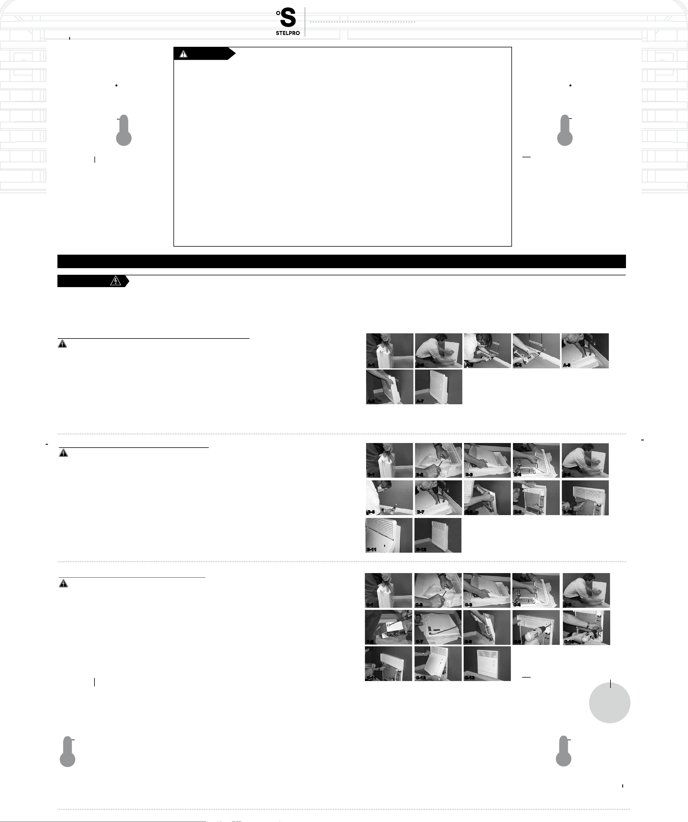
A-1 A-2 A-3 A-4 A-5
A-6 A-7
B-1 B-2 B-3 B-4 B-5
B-6 B-7 B-8 B-9 B-10
B-11 B-12
C-1 C-2 C-3 C-4 C-5
C-6 C-7 C-8 C-9 C-10
C-11 C-12 C-13
ASILVC2060 SERIES
ELECTRONIC BATHROOM CONVECTOR
USER’S gUIdE
the warranty will be considered null and void and the manufacturer deems no further responsibility for this product.
certied electrician, according to the electrical and building codes effective in your region.
The following instructions must be adhered to in order to avoid personal injuries or property damages, serious injuries and potentially fatal electric shocks.
RECOMMENDED HEATING CAPACITY:
1,25 W / cubic foot (0.03 m³)
It corresponds to 10 W / square foot (0.09 m²)
Respect distances and positions indicated in the installation section.
When mounting the unit, make sure that the anchorage used can support the total weight of the unit with the mounting brackets.
Extreme caution is necessary when any heater is used by or near
children or invalids and whenever the heater is left operating and unattended
the unit must be cleaned
The thermal protection activation indicates that the unit has been subjected to abnormal operating conditions. If the thermal protection remains activated or activates and deactivates repeatedly, it is
SAVE THESE INSTRUCTIONS
INSTALLATION
STELPRO DESIGN INC. | Saint-Bruno-de-Montarville | Québec | J3V 6L7
IMPORTANT INSTRUCTIONS
WARNINg
INSTALLATION
INSTALLATION METHOD A - SURFACE INSTALLATION ON A WALL BRACKET
Cut off power supply at circuit breaker/fuse before proceeding to the installation
Using a screwdriver, remove the metal bracket located at the back of the unit by applying pressure on the top of the bracket and pushing it backward
panel.
the supplied plate inside the plastic bag (it is longer, it is painted the same colour as the heater and it can also be used as a wire cover). Position the
plastic cable clamp on the plate and insert the power cable. Use wire connectors to safely connect the unit wires to the power cable wires. Use the
operating properly.
N.B. Cut off power supply at circuit breaker/fuse before proceeding to the installation and wiring connections. This product must be connected by a certified electrician, according to the electrical and building codes effective in your
region. Consult the wiring plan found on the unit.


