A-Star PhysioGo 400C User manual

PhysioGo 400C / 401C
–User Manual


1. Basic information
page 3 of 25 issue date 02.09.2019, release 10.0
Contents
1. INTRODUCTION .......................................................................................................................................................4
1.1 MANUFACTURER ............................................................................................................................................................. 4
2. INTENDED USE .........................................................................................................................................................5
3. DEVICE INSTALLATION AND START-UP ..................................................................................................................... 6
3.1 UNIT INSTALLATION .......................................................................................................................................................... 6
3.1.1 Mounting of accessory holders ........................................................................................................................ 6
3.1.2 Connection of accessories –General notices.................................................................................................... 6
3.1.3 Connection of laser applicator ......................................................................................................................... 6
3.1.4 Connection of DOOR remote connector ........................................................................................................... 8
3.1.5 First operation.................................................................................................................................................. 8
3.1.6 Laser therapy access code................................................................................................................................ 9
3.2 SETUP MODE................................................................................................................................................................... 9
3.2.1 Basic information ............................................................................................................................................. 9
3.2.2 Language ......................................................................................................................................................... 9
3.2.3 Global settings ................................................................................................................................................. 9
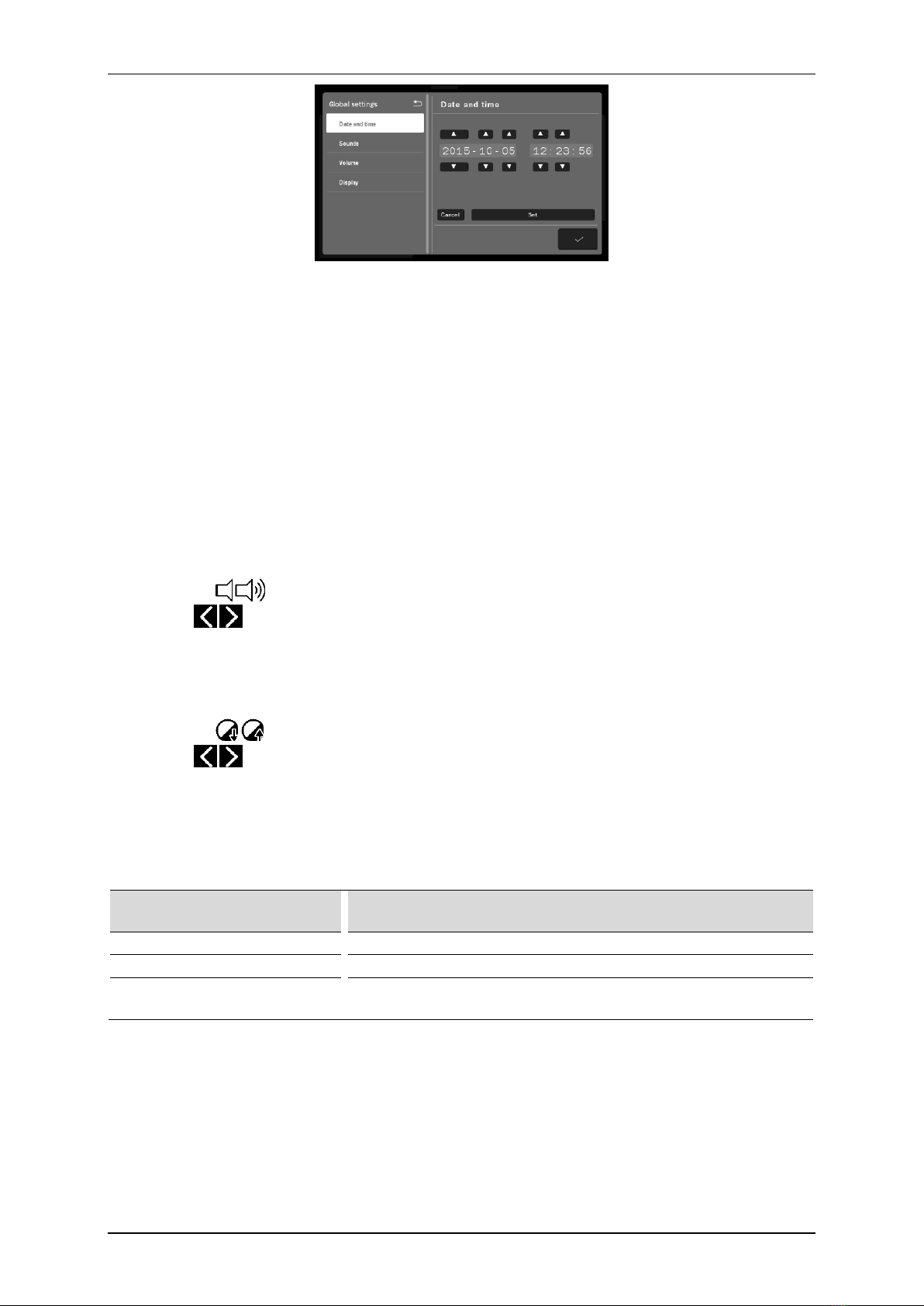
3.2.3.1 Date and time........................................................................................................................................ 9
3.2.3.2 Sounds ................................................................................................................................................. 10
3.2.3.3 Volume ................................................................................................................................................ 10
3.2.3.4 Display ................................................................................................................................................. 10
3.2.4 Functional settings ......................................................................................................................................... 10
3.2.4.1 Channel operation mode selection ..................................................................................................... 10
3.2.4.2 Program groups / medical fields.......................................................................................................... 10
3.2.4.3 Battery................................................................................................................................................. 11
3.2.5 Service............................................................................................................................................................ 11
3.2.5.1 Miscellaneous...................................................................................................................................... 11
3.2.5.2 Laser applicators output power test ................................................................................................... 11
3.2.6 Statistics......................................................................................................................................................... 12
3.2.6.1 Info ...................................................................................................................................................... 12
3.2.6.2 Unit statistics ....................................................................................................................................... 12
3.2.6.3 Accessories statistics ........................................................................................................................... 12
3.3TRANSPORT POSITION –THE STAND WITH SCANNING APPLICATOR .............................................................................................. 13
4. UNIT OPERATION................................................................................................................................................... 14
4.1 PATIENT PREPARATION AND TREATMENT PERFORMANCE ......................................................................................................... 14
4.1.1 Laser therapy ................................................................................................................................................. 14
4.2 SCREEN CONFIGURATION ................................................................................................................................................. 15
4.3 GENERAL CONFIGURATION ............................................................................................................................................... 16
4.3.1 Treatment channel configuration .................................................................................................................. 16
4.3.2 Channel selection tabs ................................................................................................................................... 17
4.4 DISPLAY DESCRIPTION ..................................................................................................................................................... 18
4.5 OPERATION WITH PRESET TREATMENT PROGRAMS ................................................................................................................. 18
4.5.1 Voll and Nogier programs .............................................................................................................................. 20
4.6 FAVORITE PROGRAMS ..................................................................................................................................................... 21
4.7 MANUAL MODE OPERATION ............................................................................................................................................. 22
4.8 USER PROGRAMS ........................................................................................................................................................... 22
5. INDICATIONS AND CONTRAINDICATIONS............................................................................................................... 24
5.1 INDICATIONS FOR LASER THERAPY....................................................................................................................................... 24
5.2 CONTRAINDICATIONS FOR LASER THERAPY ............................................................................................................................ 24
6. ACCESSORIES ......................................................................................................................................................... 25
6.1 STANDARD ACCESSORIES .................................................................................................................................................. 25
6.2 OPTIONAL ACCESSORIES................................................................................................................................................... 25
Table of figures
Figure 3.1. Laser therapy sockets ............................................................................................................................................... 7
Figure 3.2. Handwheels –scanner and arm of the stand ........................................................................................................... 7
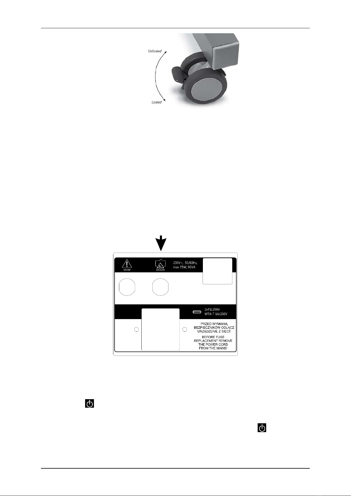
Figure 3.3. Wheel with brake ..................................................................................................................................................... 8
Figure 3.4. DOOR remote connector socket............................................................................................................................... 8
Figure 3.5. Screen view –date and time edition ...................................................................................................................... 10
Figure 4.1. Field description ..................................................................................................................................................... 15
Figure 4.2. Location of channel selection tabs ......................................................................................................................... 17
Figure 4.3. Screenshot sample view for laser therapy.............................................................................................................. 18
Figure 4.4. Information screen sample view ............................................................................................................................ 19

1. Basic information
PHG 400C / 401C User Manual Page 4of 25
1. Introduction
Read this manual carefully before starting the unit operation!
Follow the recommendations presented in this manual!
PhysioGo unit should be installed by the seller.
The recipient has the right to insist on the product operation training.
The unit may only be operated by qualified personnel or under supervision of such personnel!
WARNING: The device is intended for adult patients only. It is not intended for use in a home healthcare
environment.
Description of symbols used in this manual:
Read appropriate passage of this user manual, warnings or important information. Failure to
observe warnings can lead to injuries.
Important notices and information.
Following texts marked with this symbol facilitates device operation.
NOTE:
The outlook of screenshots shown in this manual may slightly differ from their actual outlook during device
operation. These differences may concern size and type of fonts and size of symbols. There are no differences in
the content of shown information.
Warning: No modification of this equipment is allowed!
1.1 Manufacturer
ASTAR Sp. z o.o.
ul. Świt 33
43-382 Bielsko-Biała, Poland
www.astar.eu

2. Intended use
page 5 of 25 issue date 02.09.2019, release 10.0
2. Intended use
Multifunctional unit PhysioGo 400C / 401C is an active, non-invasive therapeutic device, intended for carrying
out treatment procedures using laser radiation within the visible (for wave length 660 nm) and invisible range
(for wave length 808 nm).
Model 400C
Non battery unit
Model 401C
Battery unit
The unit is equipped with three fully independent treatment channels. The list of available applicators in
particular channels is presented in the table below.
Channel
Laser applicator type
1
Probe
Scanning applicator
Cluster applicator
2
Scanning applicator
Cluster applicator
3
Probe
Detailed information about available configurations is presented further in this manual.
The unit possesses the base of preset treatment procedures along with therapeutic encyclopedia, which
significantly increases comfort of operation.
There is a possibility to create own user-defined programs –for all laser applicators.
As regards to laser radiation, the unit may be operated with point, cluster and scanning laser applicators. Due to
the available maximum radiation power output at the level of 450 mW for wave length 808 nm and 100 mW for
660 nm, the PhysioGo unit is classified as a small power output laser device. In physiotherapy such lasers are
designated as ”cold”, ”soft”or biostimulating.
The unit is a laser therapy device class 3B.
The unit may perform treatments by laser radiation in continuous and pulse mode.
Detailed information about indications and contraindications –see section 5.
Due to the versatility and the optional availability of a battery, the unit is perfectly suited for use:
•in sports medicine in case of training camps,
•wherever there are problems with power supply quality.

3. Device installation and start-up
PHG 400C / 401C User Manual Page 6of 25
3. Device installation and start-up
3.1 Unit installation
The first installation should be performed by a qualified manufacturer’s or distributor’s representative!
After removing the unit from the carton, check if the complete unit has been delivered. In case of any
inconsistencies contact the distributor or manufacturer.
After removing the unit from transportation packaging wait approximately two hours before proceeding to
next installation steps. This is aimed at adaptation of the unit to conditions in operation room.
The unit shall be placed on a table, trolley or in a cabinet near mains socket. Due to manufacturing under safety
class I the unit can be connected only to a socket with protective earth pin. It is recommended to place the unit
at such a height that it would enable convenient operation from the front panel. The light shall enable easy
readout of display indicators, however the unit shall not be exposed to direct sunlight.
Laser applicators may only be connected to the sockets when the power supply is switched off. Connecting
of laser applicators with the power supply on may cause irreversible damage of the laser diode which is beyond
the scope of warranty repairs! Applicator connected when the mains supply is on will not be detected and its
use will not be possible!
3.1.1 Mounting of accessory holders
Mount the holders according to the information and illustrations given in chapter 4.3 of PhysioGo Technical
Description manual.
3.1.2 Connection of accessories –General notices
It should be noted that some of the connection sockets are multifunctional and different types of accessories
may be connected in. All connectors are protected against pulling out of the sockets. It is recommended to
secure the plug by tightening protection ring.
3.1.3 Connection of laser applicator
Laser applicators should be connected to laser therapy sockets according to figure 3.1. Meaning of laser
applicator symbols is shown in the table below.
Symbol
Laser applicator type
Red light point probe, type 40RDV2
Red light point probe, type 80RDV2
Red light point probe, type 80RDV3
Infrared light point probe, type 200IRV2
Infrared light point probe, type 400IRV2
Infrared light point probe, type 400IRV3
Scanning laser applicator, type SKW2-400 / SK2-400
Scanning laser applicator, type SKW2-450 / SK2-450
Cluster laser applicator, type CL1800WH / CL1800

3. Device installation and start-up
page 7 of 25 issue date 02.09.2019, release 10.0
Note:
•laser probes may be connected only to sockets 1 and/or 3,
•scanning applicator may be connected only to sockets 1 and/or 2,
•cluster applicator may be connected only to sockets 1 and/or 2.
Incorrect connection of laser applicators will result in an error message and blocking their availability.
Figure 3.1. Laser therapy sockets
Operating notes for operation with the scanning laser applicator mounted on a stand:
•The stand with a unit and applicators shall be placed near mains socket, so that the change of stand position
is not limited by the mains cable.
•When adjustment of scanner right position is difficult it is recommended to loosen or turn (depend on need)
handwheel locking the arm of the stand or handwheel locking the laser scanner (both handwheels are
presented in figure 3.2).
Figure 3.2. Handwheels –scanner and arm of the stand
•To protect the stand from unintentional change of its position it is recommended to lock wheel brakes –
brake must be pressed to the floor. To release the brake, lift it up (wheel with brake is shown in figure 3.3).

3. Device installation and start-up
PHG 400C / 401C User Manual Page 8of 25
Figure 3.3. Wheel with brake
•To disassemble the controller from the shelf it is recommended to unscrew the bolts mounted to the shelf.
•To disassemble the scanning applicator, with one hand pull the mounting protection ring and using the
other one release the scanner from the mounting socket.
•Other interconnecting cables shall be located to enable free change of position of the stand and scanning
position adjustment.
Connection between scanning applicator and controller should be done with cable run inside the stand.
It must be connected to the socket on the rear casing panel of the scanner applicator and laser therapy socket
located on the unit.
3.1.4 Connection of DOOR remote connector
DOOR remote connector socket is located on the rear panel of the unit. In order to perform laser treatment
procedures, insert the plug marked DOOR into the socket.
Figure 3.4. DOOR remote connector socket
3.1.5 First operation
Connect the unit to mains supply with delivered detachable mains cable. Switch the mains supply on. Then press
the STANDBY key to start the operation. After switching the mains supply on proper work of all blocks are
tested.
In the case of battery operation, please hold on for at least 3 seconds the STANDBY key . Extension of the
holding time prevents unintentional activation during transport.

3. Device installation and start-up
page 9 of 25 issue date 02.09.2019, release 10.0
If after switching on mains supply the display is illegible and no light indicator is illuminated, check whether
mains fuse or mains cable operate correctly. Care shall be given to apply fuses with rating given on the name
plate. If fuse and cables are working properly, contact the authorized service.
If the self-test results in appearing on the display the information about unit or connected applicator defect
along with the error code, turn the unit off and contact with an authorized service representative.
Due to safety reasons the unit was equipped with software and hardware lock of laser applicators operation.
The operation is possible only after correct entry of unique access code and inserting the remote interlock
connector (marked as DOOR) into DOOR socket, located on back panel of the enclosure (provided as standard
accessory).
3.1.6 Laser therapy access code
The code which allows for laser applicator operation has the shape of: PHGL
Entering an incorrect code prevents the execution of laser treatment procedures and laser applicator power
measurement tests.
3.2 Setup mode
3.2.1 Basic information
Keyboard components designed for the unit operation are called ”keys”.
The area on the screen, where after its pressing a specific unit reaction is followed, is called ”button”.
The area on the screen that has the possibility to select or deselect any item, is called ”selection field”.
To enter Setup mode, press
To leave Setup mode, press
To go back one level, press
Setup mode is available only if the treatment is not performed. Some setting options depend on the connected
accessories. In the absence of some accessories, the options will not be available.
3.2.2 Language
With the PhysioGo unit information on the display may be presented in different language
versions. The user is free to select language options.
To set the language version, press the Language button in the list of setup options, then press the desired version.
Language version change is immediate.
3.2.3 Global settings
3.2.3.1 Date and time
In this section there is a possibility to adjust date and time. To change these settings, press the button Edit. Using
arrows, set the required value. Confirm settings using Set button or leave the edition mode by pressing Cancel.

3. Device installation and start-up
PHG 400C / 401C User Manual Page 10 of 25
Figure 3.5. Screen view –date and time edition
3.2.3.2 Sounds
The user may configure settings of acoustic signals, which occur during unit operation. Description of available
configuration options:
•Keys sound
•Sound during treatment
•End of treatment sound
•Warning sounds
•Initial sound
In order to set the appropriate option, select or clear the selection field by its pressing.
3.2.3.3 Volume
The user may adjust sound volume level. To perform this action:
•press the volume bar at desired place, or
•use buttons on the screen, or
•use keys
3.2.3.4 Display
The user may adjust display brightness level. To perform this action:
•press the value bar at desired place, or
•use buttons on the screen, or
•use keys
3.2.4 Functional settings
3.2.4.1 Channel operation mode selection
This function allows the user to set preferred style of unit operation.
Option
Explanation
Manual mode –automatically
After therapy selection, the unit is set in manual mode operation.
Program mode –automatically
After therapy selection, the unit is set in program mode operation.
Mode selection pop-up
After therapy selection, the unit displays a window with a list of
operation mode selection options.
In order to set the appropriate option, select or clear the selection field by its pressing.
3.2.4.2 Program groups / medical fields
This function allows the user to set filters of available program mode options according to the preferred program
groups or medical fields. In order to set the appropriate option, select or clear the selection field by its pressing.

3. Device installation and start-up
page 11 of 25 issue date 02.09.2019, release 10.0
For program groups, the following options are available:
•Preset programs
•User programs
•Voll acupuncture programs –only for laser point probes
•Nogier acupuncture programs –only for laser point probes
For medical fields, instead of the preset treatment programs the following options classified by medical
nomenclature are available:
•Orthopedics
•Sports medicine
•Aesthetic medicine
•Rheumatology
•Neurology
•Urology
•Dermatology
•Angiology
The classification of preset treatment programs into the above-mentioned categories do not limit their
applications in other fields, according to the knowledge and experience of doctors and physiotherapists.
3.2.4.3 Battery
This function allows the user to set the battery charging mode.
Option
Explanation
Charge battery up to 80%
Reducing the battery power level extends its lifetime at the expense of
shorter working hours in case of mains power failure.
Charge battery up to 100%
Maximum battery working hours. Keep in mind that full battery charging
shortens its life.
3.2.5 Service
3.2.5.1 Miscellaneous
In order to exercise the option, follow the instructions shown on the display.
3.2.5.2 Laser applicators output power test
This function enables checking if the output power of laser radiation emitted by laser applicators is correct.
Laser output power test for a given applicator is only possible if it is not previously selected in a laser therapy
channel tab.
The applicator selection is performed by:
•pressing on the screen the selected field with its symbol, or
•a double press on the screen clear field with its symbol, or
•check box indication and pressing a key on the keyboard.
Laser output power measurement of point probes and scanning applicators is performed automatically, the
results are displayed on the screen. Laser output power measurement of the cluster laser applicator is possible
by the use of external radiation sensor.
During this procedure it is recommended to follow the instructions shown on the display.

3. Device installation and start-up
PHG 400C / 401C User Manual Page 12 of 25
To measure output laser power of the laser applicator:
Step
Description
1.
Enter the setup mode. Select Service tab, then select Laser applicators output power test.
2.
Select the channel. Connected applicator is identified in the Accessory field.
3.
Press Run the power measurement button.
4.
Enter the access code: PHGL. Confirm the code by pressing key or button
5.
An instruction window depending on the type of tested applicator will appear on the screen. Follow
the steps according to the instructions.
6.
Verify the measured value.
7.
To complete the procedure, press the key or button
If measurement power is different more than ±20% from nominal power it is recommended to repeat the
measurement. The cause of incorrect indication of emitted output power may be:
•fault of the laser applicator,
•heavily soiled laser diodes or optical elements.
In case, when results of five consecutive measurements are incorrect, contact the authorized service.
3.2.6 Statistics
3.2.6.1 Info
Provides information about the version of the unit, software, interface and software build date.
3.2.6.2 Unit statistics
Provides information about the number of treatment procedures performed. Statistics can be deleted. If you
want to delete statistics, press Delete programs counters button.
3.2.6.3 Accessories statistics
Provides information about the connected accessories.

3. Device installation and start-up
page 13 of 25 issue date 02.09.2019, release 10.0
3.3 Transport position –the stand with scanning applicator
Step
Description
1.
Proceed with the treatment to the end or stop it by pressing the key
2.
Put the equipment back.
3.
Click the UNIT ON / OFF (STANDBY) button on the front panel .
4.
A message will appear on the display:
5.
Press to shut down the system correctly.
6.
Switch the mains rocker off.
7.
Disconnect the mains cable and all applicators except the scanner from the device.
8.
Then unlock the brakes and transport the stand.
9.
Transport the stand.
10.
After arranging the stand in the destination place, lock the brakes.
11.
Connect the mains cable and applicators to the device.

4. Unit operation
PHG 400C / 401C User Manual Page 14 of 25
4. Unit operation
The unit may operate in one of two modes:
•program mode,
•manual mode.
Notes –unit operation:
•In the program mode you can use preset procedures of treatment programs and user-defined programs.
•In the program mode you cannot edit the preset programs parameters. However, they can be easily ”copied”
to the manual mode. In order to do it, press the button .
•There is a possibility to repeat the completed treatment. In order to do it, press on the keyboard or
screen.
4.1 Patient preparation and treatment performance
To perform safe and effective treatment procedure you are obliged to:
•interview the patient, by taking into consideration relative and absolute contraindications to use laser
therapy –it is not recommended to carry out treatments in the patients with neurological disorders,
synkineses, trembling and convulsions,
•patient should be placed in a comfortable position, while ensuring the tissue relaxation at the site of
therapy, in case of treatment performed near the head, the patient should be in lying position.
•sitting or reclining position should be applied to patients with respiratory disorders or breathing difficulties,
•explain to each patient the applicable safety rules during laser therapy treatments,
•make the patient wear the appropriate protective glasses,
•inform the patient about the sensations occurring during therapy.
The treatment effectiveness depends on the choice of parameters to the current patient’s condition. The
patient’s condition changes over time. Its observation and assessment should take place before, during and
after therapy. Such an action is necessary for changing the parameters in order to adapt them to the actual
condition of the patient.
It is recommended to keep the records of treatment, including the parameters of the therapy, the area of
treatment, treatment technique, dose and symptoms after therapy. If the treatment does not generate the
intended effects, change of treatment parameters should be taken into consideration. It is necessary to
continuously update knowledge and follow literary activities in the scope of therapy.
When performing therapy, it is recommended to follow the guidelines given in the following section.
4.1.1 Laser therapy
•Prior to treatment it is necessary to explain to each patient the applicable safety rules during laser
therapy treatments.
•Prior to the treatment, the operator and patient must wear properly matched protective goggles.
•Before the treatment it is necessary to check the efficiency of functioning of the device and to control
condition of the applicator and periodic power measurement –see 3.2.5.2.
•Therapeutic dose is described as energy density and is expressed in J/cm2. Dose of radiation must be
adapted to the goals of therapy.
•Technical parameters of the equipment, that is the wave length and surface of an applicator, have direct
impact on the dose of radiation.
•Methods of application (point applicator –contact, cluster applicator –contact, contactless), scanning
applicator (contactless) is adapted depending on the size of application area and the goal of therapy.
•It is necessary to follow the recommendations provided below when choosing energy density:
▪at the beginning of treatment series and in acute conditions it is necessary to use smaller doses up
to 4 J/cm2–it is always necessary to observe the reaction of the patient’s organism,

4. Unit operation
page 15 of 25 issue date 02.09.2019, release 10.0
▪in chronic conditions –doses higher than 4 J/cm2.
•In therapy it is allowed to use the following application techniques:
▪single point or several points within a given area (e.g. painful points or acupuncture points, wound
along the edges or within a small distance from the wound, within a knuckle),
▪grid method and scanning (large surfaces).
•In each technique it is necessary to ensure that the radiation beam is at right angle on the tissue.
4.2 Screen configuration
Figure 4.1. Field description
Symbol
Display
Description
1
Status tab
Date and time
Battery
Quality level battery charging symbols
80%
Percentage of charging level
Eco battery mode –charging up to 80%
Mains cable connected
2
Main menu
Therapy selection menu
Program mode
Manual mode
User-defined treatment programs edition mode
Information mode
Setup mode

4. Unit operation
PHG 400C / 401C User Manual Page 16 of 25
Symbol
Display
Description
3
Edition field
This field shows:
•available therapies
•treatment parameters in manual mode
•preset treatment program lists
•user-defined program lists
•settings
4
Channel
selection tabs
Details are described in chapter 4.3.2.
Note: If the edition / main menu field is grayed out, it means that it is inactive.
4.3 General configuration
4.3.1 Treatment channel configuration
Channel
Therapy
1
•red light probe, type
40RDV2, 80RDV2/80RDV3
•infrared light probe, type
200IRV2, 400IRV2/400IRV3
•scanning laser applicator,
type SK2-400/SKW2-400 or
SK2-450/SKW2-450
•cluster laser applicator, type
CL1800/CL1800WH
2
•scanning laser applicator,
type SK2-400/SKW2-400 or
SK2-450/SKW2-450
•cluster laser applicator, type
CL1800/CL1800WH

4. Unit operation
page 17 of 25 issue date 02.09.2019, release 10.0
Channel
Therapy
3
•red light probe, type
40RDV2, 80RDV2/80RDV3
•infrared light probe, type
200IRV2, 400IRV2/400IRV3
4.3.2 Channel selection tabs
The screen displays three channel selection tabs. They present:
•selected applicator symbol,
•treatment time,
•information related to the particular channel operating status.
The color of the tab is identical to the background color of the edition field. In the background, other operating
tabs are black.
Figure 4.2. Location of channel selection tabs
The table below explains the meaning of the symbols presented in tabs:
Symbol
Treatment channel
Description
1 or 3
Selected laser therapy –laser point probes
1 or 2
Selected laser therapy –scanning laser applicator
1 or 2
Selected laser therapy –cluster laser applicator
Any
Ongoing treatment
Any
Treatment interrupted
Any
Ready to start amplitude adjustment or pause.
Any
Channel error (yellow symbol)

4. Unit operation
PHG 400C / 401C User Manual Page 18 of 25
4.4 Display description
Display
Description
Output signals of circuits
and amplitude settings
identifiers
Laser circuit
Amplitude settings:
•output energy and power emitted by laser applicator
Information field
Laser radiation emission.
Time indication
Presentation of the treatment elapsing time.
Examples of treatment display is presented below.
Figure 4.3. Screenshot sample view for laser therapy
Symbol
Description
1
Applicator identification / Program name
2
Output power
3
Presentation of the treatment elapsing time
4
Information field
5
Tab field –channel 1
4.5 Operation with preset treatment programs
The simplest method of unit’s operation is to use its preset programs. The unit includes a database containing
several dozens of most frequently met disorders together with suggested treatment types and parameters. In
this mode, the operation is reduced to selection of disease entity from the list.
The values of the preset treatment programs parameters are based on the available literature data and they
are determined as average values. Parameters should be treated exclusively as indications. Sole responsibility
for application of preset treatment programs bears the User.

4. Unit operation
page 19 of 25 issue date 02.09.2019, release 10.0
Symbol definition and parameter range are specified in the PhysioGo –Technical description manual.
Pressing the button after program selection results in appearing information which contains:
•technique description of conducting laser irradiation,
•illustrations with highlighted points or areas of the body covered by the treatment,
•suggested number of procedures, the frequency of repetition,
•impact on the patient,
•notes,
•treatment parameters.
Figure 4.4. Information screen sample view
Information mode navigation:
Symbol
Explanation
Approval of the program and return to the list (the current position)
Back to the list of preset programs on a position from which there was an
encyclopedia entry
Go to the next program
Go to the previous program
Model of the human body –go to the previous / next illustration for the program
Use keys or a bar located on the right side of the display to scroll the information.
If it is necessary to interrupt the treatment procedure (pause), press STOP key. To resume the treatment
procedure, it is recommended to follow the instructions shown on the display.
Schematic procedures for laser therapy are presented below. In continuous operation, it is recommended to
start the treatment procedure from step 3 of the scheme.

4. Unit operation
PHG 400C / 401C User Manual Page 20 of 25
Operation scheme:
Step
Description
1.
Connect an appropriate laser applicator.
2.
Switch on the unit.
3.
Enter the access code: PHGL. Confirm by the key or button
4.
Choose the treatment channel 1, 2 or 3.
5.
Select the applicator: / /
6.
Press the field Program modes
7.
Select the option Preset programs from Program modes menu. Confirm by the key or once again
press the selected field.
8.
Select the program from the list.
9.
Prepare the patient for the treatment according to indications in point 4.1.
10.
Press the key
scanning applicator
cluster applicator
point applicator
Set the shape and size of the
treatment area as well as
default scanner distance.
Set the treatment area.
Press the key
Set the treatment area.
Press the key
Press the key
Press the button on the
applicator.
Press the button on the probe.
Start of emission is signaled acoustically. Laser radiation starts after two seconds after pressing the button
on the probe.
NOTE:
Using the methods of control, adjustment or performance of procedures other than those specified herein
may result in exposure to hazardous laser radiation.
4.5.1 Voll and Nogier programs
A specific group of preset treatment programs are positions dedicated to biostimulation laser point acupuncture
according to Voll and Nogier, the so-called Voll and Nogier frequencies. These programs are only available for
low lever laser point applicators. To select the program, proceed exactly as when choosing a preset treatment
program.
This manual suits for next models
1
Table of contents
Other A-Star Medical Equipment manuals

A-Star
A-Star PhysioGo 300A User manual

A-Star
A-Star PhysioMG User manual

A-Star
A-Star PhysioGo.Lite Laser User manual

A-Star
A-Star Tecaris User manual

A-Star
A-Star PhysioGo.Lite Sono User manual

A-Star
A-Star PhysioGo.Lite Electro User manual

A-Star
A-Star PhysioGo 600C User manual

A-Star
A-Star Lumina User manual

A-Star
A-Star PhysioGo 700C User manual