Rocket Medical Rocket Digital Oocyte Aspiration Pump User manual

SERVICE MANUAL
Rocket® Digital
Oocyte Aspiration Pump

Rocket® Digital Oocyte Aspiration Pump –ServiceManual
Copyright© 2013-20 Rocket Medical plc.
All rights reserved.
ZDOCK258
Rev:09
2020-11-10
2
CONTENTS
2. GENERAL ASSEMBLY ...........................................................................................................................................3
2.1.
ROCKET DIGITAL OOCYTE ASPIRATION PUMP.............................................................................................3
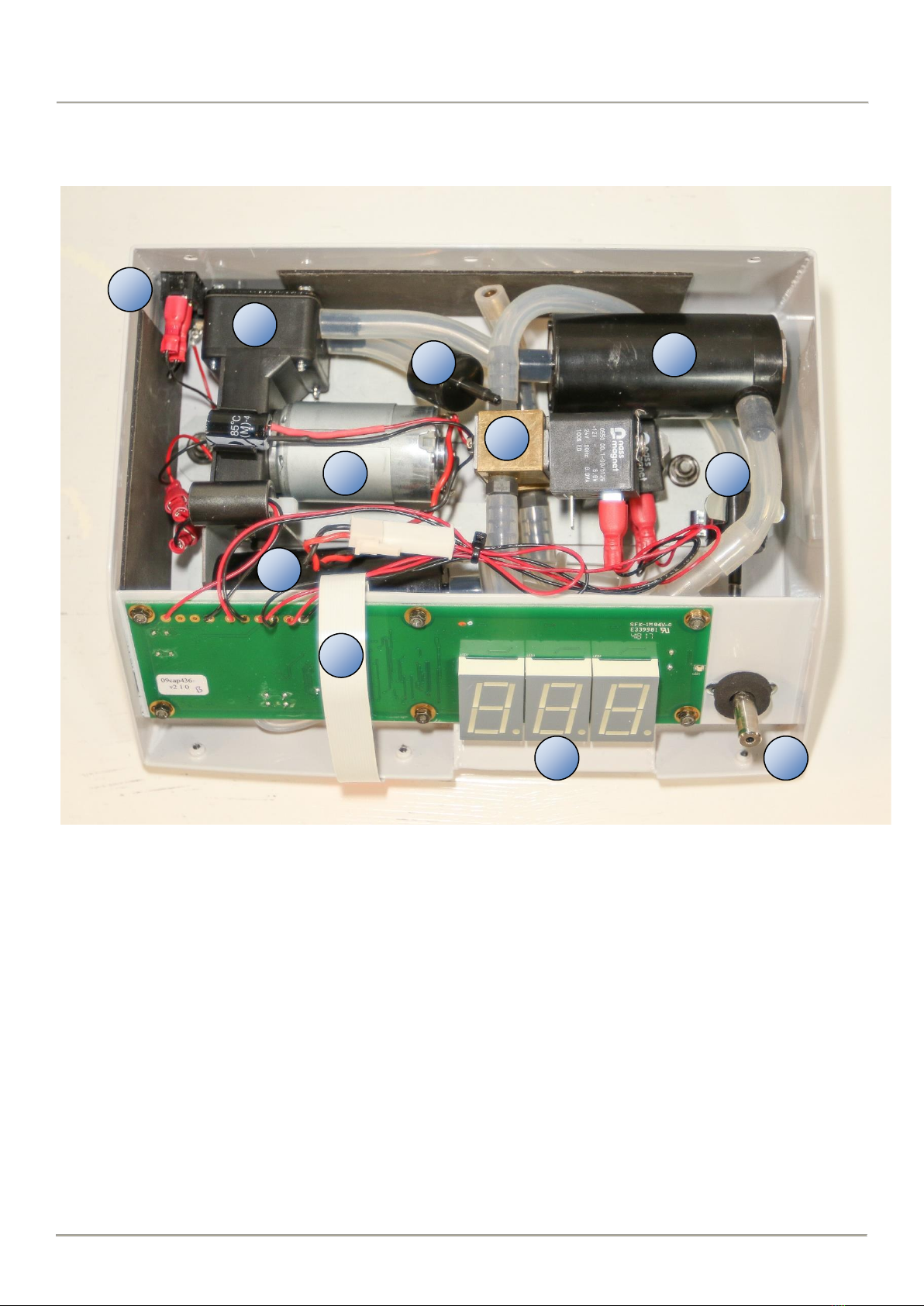
2.2.
ROCKET DIGITAL OOCYTE ASPIRATION PUMP –INTERNAL VIEW ..............................................................4
3. GENERAL DESCRIPTION......................................................................................................................................5
3.1.
INDICATIONS.....................................................................................................................................................5
3.2.
CONTRAINDICATIONS......................................................................................................................................5
3.3.
CLASSIFICATION..............................................................................................................................................5
3.4.
REFERENCES...................................................................................................................................................5
4. GENERAL INFORMATION....................................................................................................................................6
4.1.
COPYRIGHT......................................................................................................................................................6
4.2.
MODEL NUMBER...............................................................................................................................................6
4.3.
MANUAL REVISION...........................................................................................................................................6
4.4.
MANUFACTURER..............................................................................................................................................7
4.5.
SERVICE AGENTS ............................................................................................................................................7
4.6.
SUPPLY VOLTAGE SELECTION.......................................................................................................................8
4.7.
ELECTROMAGNETIC COMPATIBILITY.............................................................................................................8
4.8.
PACKAGING......................................................................................................................................................8
4.9.
POSITIONING AND PLACEMENT OF THE DEVICE..........................................................................................8
4.10.
SYMBOLS USED ON OOCYTE ASPIRATION PUMP.........................................................................................9
4.11.
SYMBOLS USED ON POWER SUPPLY UNIT..................................................................................................10
4.12.
SYMBOLS USED ON R57686 PATIENT CONNECTION SET...........................................................................10
5. ANNUAL SERVICE .............................................................................................................................................11
5.1.
REPLACING THE INLET FILTER (F02-004S)....................................................................................................12
5.2 REPLACING THE PUMP VALVE AND DIAPHRAGM SET: S02-072 ................................................................14
5.3. REASSEMBLING THE CHASSIS INTO THE CASING.......................................................................................17
6. FINAL TESTING ..................................................................................................................................................19
7. CLEANING THE PUMP CASING ..........................................................................................................................20
8. YEAR OF MANUFACTURE..................................................................................................................................20
9. RETURNING THE PUMP FOR REPAIR OR SERVICE ..............................................................................................20
10. TROUBLESHOOTING .........................................................................................................................................21
10.1 DEVICE DOES NOT POWER ON.....................................................................................................................21
10.2 DEVICE DOES NOT PRODUCE SUCTION ......................................................................................................21
10.3 DEVICE DISPLAY VARIES WHEN UNIT OPERATING.....................................................................................21
11. STORAGE AND TRANSPORTATION..................................................................................................................22
12. OPERATING CONDITIONS ...............................................................................................................................22
13. WARRANTY......................................................................................................................................................23
14. DISPOSAL:.........................................................................................................................................................23
15. TECHNICAL SPECIFICATIONS ...........................................................................................................................24
15.1.
CLASSIFICATION ............................................................................................................................................24
15.2.
SPECIFICATIONS............................................................................................................................................24
16. DRAWINGS.......................................................................................................................................................25
16.1.
SET-UP FLOW CHART....................................................................................................................................25
16.2.
PUMP TIMER RESET FLOWCHART................................................................................................................26
16.3.
SERVICE MODE RESET FLOWCHART...........................................................................................................27

Rocket® Digital Oocyte Aspiration Pump –ServiceManual
Copyright© 2013-20 Rocket Medical plc.
All rights reserved.
ZDOCK258
Rev:09
2020-11-10
3
2. GENERAL ASSEMBLY
2.1.
ROCKET DIGITAL OOCYTE ASPIRATION PUMP
1.
Touch sensitive Suction Control Dial –clockwise to increase the set value and anticlockwise to decrease
2.
Suction Display in mmHg-1
3.
Patient Connection Port –only for use with R57686 Rocket Oocyte Aspiration Pump Patient Connection Sets
4.
Power On Indicator LED (Green, 12V DC)
5.
Footswitch Connection Ports
6.
User Set Suction Indicator LED (Blue, 50-300mmHg-1)
7.
Pre-set (Max) Suction Indicator LED (Orange, 500mmHg-1)
8.
Service Indicator LED (Yellow)
9.
O/I 12V Power On/Off switch
10.
Dual Footswitch –air controlled
Not shown:
11.
Power Supply Unit (PSU) Model: MPU30
12.
Power Cords, IEC UK & EC types
1
2
3
4
5
6
7
8
9
10
0
0
0

Rocket® Digital Oocyte Aspiration Pump –ServiceManual
Copyright© 2013-20 Rocket Medical plc.
All rights reserved.
ZDOCK258
Rev:09
2020-11-10
4
2.2.
ROCKET DIGITAL OOCYTE ASPIRATION PUMP –INTERNAL VIEW
1.
O/I Mains Power On/Off
2.
Vacuum Display 0-500mmHg-1 –normal range 50-300mmHg-1
3.
12V Motor
4.
Pump Head including Valve Housing
5.
Vacuum Outlet Port
6.
Vacuum Inlet Filter
7.
Vacuum Control Solenoid
8.
Internal Silencer with Filter Chamber (A)
9.
Internal Silencer with Filter Chamber (B)
10.
Internal Exhaust Vent and Filter
11.
Control PCB with ribbon cable to vacuum control touch wheel
8
5
2
1
10
3
4
6
7
9
11

Rocket® Digital Oocyte Aspiration Pump –ServiceManual
Copyright© 2013-20 Rocket Medical plc.
All rights reserved.
ZDOCK258
Rev:09
2020-11-10
5
3. GENERAL DESCRIPTION
The Rocket Oocyte Aspiration Pump has been developed to provide smooth, low volume/high suction (vacuum) at a pre-
determined negative pressure. Suction is activated by a foot-operated, toggle air-switch, controlled by the surgeon performing the
oocyte collection.
The range of suction is variable, from 50 to 300mmHg-1 and at a preset 500mmHg-1 in ‘Max’ suction mode.
The Rocket Oocyte Aspiration Pump requires a disposable filter set, R57686, for attachment of the pump to the oocyte collection
needle. The filter set is supplied separately, sterile and for single patient use.
You will also require:
•
A suitable oocyte aspiration needle such as Rocket SX Single Lumen Oocyte Aspiration Set (R57603-SX-90)
•
Suitable collection tubes for use with oocyte needle sets such as a Falcon® test tube, 17 x 100mm
•
Flushing media
3.1.
INDICATIONS
For the generation of high vacuum/low volume suction between 50 and 500 mmHg-1 to permit the aspiration of follicular fluid,
oocytes and ovarian fluid as part of the treatment of infertility relating to IVF and other gynaecological procedures.
3.2.
CONTRAINDICATIONS
Not intended for use where ovarian aspiration or the aspiration of ovarian fluid is contraindicated. For short term operation only.
The device is NOT intended for continuous drainage.
3.3.
CLASSIFICATION
•
IEC 60601-1: 2005
•
Type of protection against electric shock: Class II
•
Degree of protection against electric shock: Type B
•
Vacuum type: high vacuum/low volume
•
Suitable for continuous operation
•
Not suitable for use in the presence of flammable gases
•
Not suitable for use in conditions which expose the device to the ingress of fluids
•
Not suitable for sterilization
3.4.
REFERENCES
Craft I, McLeod F. Edmonds K, ‘Human embryo transfer technique’. Lancet 1961 ii 1104-5
Craft I, Diahanbakch O. McLeod F et al ‘Human pregnancy following oocyte and sperm transfer to the uterus.’ Lancet 1992 i 1031-3
Craft I, (1984) ‘Clinical Methodology’ British Journal of Hospital Medicine 90-102
Reeves G, Scott R T, et al (1989) Journal of Assisted Reproduction and Genetics Volume 6, Number 6 / December, 1989

Copyright© 2013-20 Rocket Medical plc.
All rights reserved.
ZDOCK258
Rev:09
2020-11-10
Rocket® Digital Oocyte Aspiration Pump –ServiceManual
6
WARNING: READ
THIS MANUAL
CAREFULLY: Please
familiarise yourself with the
contents of this manual
before attempting to use
the device.
Failure to observe these
instructions may result in
damage to the pump or
cause injury to the patient
or user.
This device should only be
used by or under the
supervision of suitably
qualified personnel.
WARNING: ELECTRIC
SHOCK HAZARD.
The equipment is to be
used only with electrical
systems complying with all
IEC, CEC and NEC
requirements.
4.GENERAL INFORMATION
4.1.
COPYRIGHT
This manual contains information that is subject to copyright. All rights reserved.
This manual should not be photocopied, duplicated or distributed completely, or in part, without
the written approval of Rocket Medical plc.
4.2.
MODEL NUMBER
Rocket Digital Suction Pump Complete R29700
Power Supply MPU30
4.3.
MANUAL REVISION
Revision 1 First Publication 05/11/13
Revision 2 Update of LRQA CE mark 27/08/14
Revision 3 Update to EN 60601-1:2006 10/07/16
Revision 4 Correction PSU current and voltage 10/08/16
Revision 5 Correction of operating temperature 12/08/16
Revision 6 Update cover image, add flowcharts 21/01/19
Revision 7 Update service agent, warranty 25/02/19
Revision 8 Update CE Mark 25/08/20
Revision 9 Update Service Instructions 10/11/20

Copyright© 2013-20 Rocket Medical plc.
All rights reserved.
ZDOCK258
Rev:09
2020-11-10
Rocket® Digital Oocyte Aspiration Pump –ServiceManual
7
4.4.
MANUFACTURER
Rocket Medical plc.,
Sedling Road,
WASHINGTON,
Tyne & Wear
NE38 9BZ,
United Kingdom.
CAUTION:
Any adjustment,
modification or repairs to
the equipment should be
carried out by authorised
service agents.
Disposal of this device
must be undertaken with
regard to the WEEE
directive (2002/96/EC).
4.5.
SERVICE AGENTS
Rocket Digital Pumps require servicing when indicated by the Service Indicator.
It is recommended they are serviced and calibrated at an approved Rocket Medical plc.
service facility.
Failure to service the pump at the indicated intervals and with an authorised service
agent may invalidate the Warranty.
UK & European Service Agents:
IVFSynergy Ltd.,
Old School,
Tresillian,
Cornwall
TR2 4BA
United Kingdom.
Tel: +44 (0) 1872 487224
E: service@ivfsynergy.com
W: www.ivfsynergy.co.uk
Australian Service Agent
DTS Q-Tech,
8/79 Newton Road,
Wetherill Park, NSW 2164
Australia
Tel: +61 2 9729 4214
Email: terry@dtsdiagnostics.com.au
Website: www.dtsqtech.solutions
Rocket Medical GmbH
Am Rosengarten 48,
15566 Schöneiche.
Germany
UK Customer Services:
Rocket Medical plc., Sedling Road, WASHINGTON NE38 9BZ, UNITEDKINGDOM
Tel:
+44 (0) 191 419 6988. Fax: +44 (0) 191 419 6989
Email: customerservices@rocketmedical.com

Copyright© 2013-20 Rocket Medical plc.
All rights reserved.
ZDOCK258
Rev:09
2020-11-10
Rocket® Digital Oocyte Aspiration Pump –ServiceManual
8
WARNING: ELECTRIC
SHOCK HAZARD.
The equipment is to be
used only with electrical
systems complying with all
IEC, CEC and NEC
requirements.
WARNING: ELECTRIC
SHOCK HAZARD.
Do not immerse the
device.
WARNING:
Device can cause
explosion in the presence
of flammable gases.
4.6.
SUPPLY VOLTAGE SELECTION
The device is only for use with power supply Model Number: MPU30 with 12V DC output.
Attachment of any other power supply may severely damage the device.
CAUTION: Disconnection from the mains supply can only be achieved with the removal of the
mains power lead from the wall socket.
The device operates at a voltage 100V to 240 VAC @ 50 / 60Hz. 0.15A.
4.7.
ELECTROMAGNETIC COMPATIBILITY
Rocket Craft Suction Pumps comply with the electromagnetic compatibility (EMC) limits for
medical devices as specified by EN 60601-1-2:2015. These limits are designed to provide a
reasonable degree of protection against harmful interference found in typical medical installations.
Medical electrical equipment requires special precautions regarding EMC and the device must be
installed, positioned and operated according to the instructions contained in this manual to ensure
continued electromagnetic compatibility.
The device must be operated according to the instructions contained in this manual to
ensure continued electromagnetic compatibility.
4.8.
PACKAGING
The packaging has been designed to allow secure transportation of the pump and its
accessories.
After unpacking, re-assemble and retain the packaging for transport for servicing when
required.
4.9.
POSITIONING AND PLACEMENT OF THE DEVICE
Rocket Digital Oocyte Aspiration Pumps must be placed on a secure, level surface, away from
sources of heat, water splashes, mists or cooling vents.
Do not expose to direct sunlight.
Do not expose to flammable gases.
Operating temperature range: +5°C to +40°C

Copyright© 2013-20 Rocket Medical plc.
All rights reserved.
ZDOCK258
Rev:09
2020-11-10
Rocket® Digital Oocyte Aspiration Pump –ServiceManual
9
4.10.
SYMBOLS USED ON OOCYTE ASPIRATION PUMP
12 V DC Power ON/OFF.
This device operates on 12V DC power provided by a
separate power supply module supplied with the device.
Disconnection from the mains supply can only be achievedwith the
removal of the mains power lead from the wall socket.
This device is Type B
Connection point for filter set
Footswitch connection
This device is powered by a Class II
power supply unit
Indicates the service interval indicator
Suction display touch control symbol.
Indicates activation of the pre-set (Max) 500mmHg-1 mode
Indicates activation of the user set 50-300mmHg-1 mode
Dispose of this device in accordance with
WEEE directive (2002/96/EC)
CE Mark
Consult the Instructions for Use
CAUTION: consult accompanying documents
SN
Indicates device serial number
Indicates manufacturer

Copyright© 2013-20 Rocket Medical plc.
All rights reserved.
ZDOCK258
Rev:09
2020-11-10
Rocket® Digital Oocyte Aspiration Pump –ServiceManual
10
4.11.
SYMBOLS USED ON POWER SUPPLY UNIT
Read the manual before connection and use
WARNING: Risk of electric shock.
The power supply unit should not be opened
This device is only for use indoors
Class II power supply unit
12V DC connection polarity
Dispose of this device in accordance with
WEEE directive (2002/96/EC)
The power supply unit conforms to EN60601-1 & IEC60601-1
CE Mark
4.12.
SYMBOLS USED ON R57686 PATIENT CONNECTION SET
Read the Instruction for Use before connection and use
Device is for Single Use Only
Batch number for sterile device
Device is sterilised by Ethylene Oxide
The device is not manufactured with natural latex
CE Mark

Copyright© 2013-20 Rocket Medical plc.
All rights reserved.
ZDOCK258
Rev:09
2020-11-10
Rocket® Digital Oocyte Aspiration Pump –ServiceManual
11
5.ANNUAL SERVICE
Service Kits:
Filter Service Kit: F02-004s
Pump Service Kit: S02-072
Tools required:
a) Pozidriv 1 Screwdriver
b) 8mm Nut Runner
c) 2mm Hex Key

Copyright© 2013-20 Rocket Medical plc.
All rights reserved.
ZDOCK258
Rev:09
2020-11-10
Rocket® Digital Oocyte Aspiration Pump –ServiceManual
12
5.1.
REPLACING THE INLET FILTER (F02-004S)
Lay the pump on a clean surface,
protecting the casing from scratches.
Remove the 3 screws and washers
from the rear casing and retain.
Turn the pump over and remove the
3 screws and washers from the front
lower casing and retain.
Remove the white silicone retaining
‘O’ ring from the vacuum inlet port.
WARNING:
Observe precautions for
handling electrostatic
discharge sensitive
devices
CAUTION: Avoid the use
of sharp tools as these
may damage the O’ ring.

Copyright© 2013-20 Rocket Medical plc.
All rights reserved.
ZDOCK258
Rev:09
2020-11-10
Rocket® Digital Oocyte Aspiration Pump –ServiceManual
13
Detach the ribbon cable from the
front panel vacuum controller PCB
by lifting the tab.
Carefully detach the ribbon from the
front cover and store securely.
Detach the patient outlet filter from
the tube.
Unclip the filter from the spring clip;
discard and replace the filter.

Copyright© 2013-20 Rocket Medical plc.
All rights reserved.
ZDOCK258
Rev:09
2020-11-10
Rocket® Digital Oocyte Aspiration Pump –ServiceManual
14
5.2 REPLACING THE PUMP VALVE AND DIAPHRAGM SET:
S02-072
Unscrew the two securing nuts and
lift out the chassis to gain access to
the pump head.
Angle the chassis to support it on the
casing.
Unscrew the 4 screws from the
pump head in a crosswise manner to
prevent distortion of the pump head
Disconnect the pipe connected to
the inlet, and the filter connected to
the outlet.

Copyright© 2013-20 Rocket Medical plc.
All rights reserved.
ZDOCK258
Rev:09
2020-11-10
Rocket® Digital Oocyte Aspiration Pump –ServiceManual
15
Unscrew the center diaphragm
screw.
Remove the diaphragm to reveal the
piston head.
Retain the metal plate and screw and
discard the diaphragm.
Ensure the piston is free to move and
that there is no contamination or
corrosion present.
The service kit contains only the
parts on the left. Retain the parts
circled, on the right, from the unit.
Centralise the piston into the
housing and re-attach the diaphragm,
plate and screw.
DO NOT OVERTIGHTEN THE
SCREW
IMPORTANT
IMPORTANT

Copyright© 2013-20 Rocket Medical plc.
All rights reserved.
ZDOCK258
Rev:09
2020-11-10
Rocket® Digital Oocyte Aspiration Pump –ServiceManual
16
Refit the head to the pump.
IMPORTANT: Note valve and
head orientation
Discard the old gasket and use a new
replacement with the existing metal
plate and 4 screws.
Tighten the head screws in a
crosswise fashion to avoid distorting
the head.
DO NOT OVERTIGHTEN THE
SCREWS
Re-attach the inlet vacuum tubing to
the inlet.
Re-attach the exhaust filter to the
bottom port and relocate between
the motor and the inlet tubing.
Return the chassis to the casing,
locating it onto the threaded bosses
within the case.
Refit the washers and nuts and
tighten the securing nuts.
IMPORTANT
IMPORTANT

Copyright© 2013-20 Rocket Medical plc.
All rights reserved.
ZDOCK258
Rev:09
2020-11-10
Rocket® Digital Oocyte Aspiration Pump –ServiceManual
17
5.3.REASSEMBLING THE CHASSIS INTO THE CASING
Pass the inlet filter underneath the
tubing and refit it in the clip.
Re-attach the filter to the patient
connection port tube.
Ensure that the tubing is not trapped
by the spring clip and is correctly
routed to avoid occlusion.
Ensure that the filter tubing is not
kinked.
Re-attach the ribbon cable from the
PCB to the front panel vacuum
controller PCB by lifting the tab.
Carefully insert the ribbon and close
the tab securely.
Lay the pump on a clean surface,
protecting the casing from scratches.
Re-fit the casing taking care of the
ribbon cable.
After re-fitting the upper casing to
the lower frame, re-install the 3
screws and washers to the rear
casing.
VERY
IMPORTANT
IMPORTANT DO
NOT OVER
TIGHTEN THE
SCREWS

Copyright© 2013-20 Rocket Medical plc.
All rights reserved.
ZDOCK258
Rev:09
2020-11-10
Rocket® Digital Oocyte Aspiration Pump –ServiceManual
18
Turn the unit over and re-install the
3 screws and washers to the front
lower casing.
Re-install the white silicone retaining
‘O’ ring to the vacuum inlet port.
IMPORTANT DO
NOT OVER
TIGHTEN THE
SCREWS
CAUTION: Avoid the use
of sharp tools as these
may damage the O’ ring.

Copyright© 2013-20 Rocket Medical plc.
All rights reserved.
ZDOCK258
Rev:09
2020-11-10
Rocket® Digital Oocyte Aspiration Pump –ServiceManual
19
6.FINAL TESTING
1.
Final testing should be
completed with a validated and
independently calibrated
electronic vacuum gauge or
similar device.
2.
Required operating scale:
10-500mmHg in 1mmHg
increments
3.
Attach the vacuum test gauge
as indicated in the image
below to the external vacuum
port.
4.
Attach the footswitch as for
normal operation.
5.
Power the device on.
WARNING:
Ensure the vacuum levels
are within the specified
accuracy tolerance before
returning the pump to
clinical service.
6.
On Start-Up, the pump is pre-
set to 100mmHg-1 suction. To
increase this value, use a
circular motion, lightly drawing
a finger clockwise over the
outer zone of the control dial
in the direction of the arrows.
7.
The active dial zone will
sense the motion and
increase the display in
5mmHg-1 increments.
8.
To decrease the set value, use
an anticlockwise circular
motion.
9.
When the desired value is
reached, hold the finger still
for 2 seconds when an
audible ‘beep’ will confirm the
new setting.
10.
Activate the Standard Vacuum
footswitch –observe that the
suction indicator is illuminated.
11.
Record the vacuum
registered for each of the
test values.
Specified accuracy: ±10% of test value
Test
Value
Indicated
Vacuum
Test Gauge
100mmHg
150mmHg
200mmHg

Rocket® Digital Oocyte Aspiration Pump –ServiceManual
20
Copyright© 2013-20 Rocket Medical plc..
All rights reserved.
ZDOCK258
Rev:09
2020-11-10
WARNING:
ELECTRIC SHOCK
HAZARD.
Do not immerse the device
or power supply.
WARNING:
Do NOT attempt to sterilise
the device
WARNING:
Protect the device from
ingress of liquid. Should any
liquid enter the device,
discontinue use immediately
and refer to an authorised
service agent
HAZARD:
Do NOT include used
consumables as these
pose a significant
contamination risk
IMPORTANT
A decontamination
certificate MUST be
included with every
returned pump.
Repair or servicing cannot
be commenced unless the
service agent is in
possession of this
certificate
7. CLEANING THE PUMP CASING
At the end of each clinical session, turn off the device at the rear panel and disconnect the power
supply unit from the mains power supply.
Using an aqueous 70% alcohol solution (eg. IMS or isopropyl BP), moisten a cloth and wipe all
external surfaces of the device. If the surface has become contaminated with proteinaceous material,
remove with a light detergent solution before surfacing cleaning with an alcohol solution.
Do NOT use a 100% alcohol or any other solvent to clean the device as this may cause damage to
the casing surface and display.
Prevent any fluid from entering the device.
8. YEAR OF MANUFACTURE
9. RETURNING THE PUMP FOR REPAIR
OR SERVICE
Except under warranty, all service and/or repair should be organized via an authorized Service
provider. For warranty repairs, please contact Rocket Medical customer services.
Prior to shipping, all devices must be prepared as described below, for the protection of the
servicing team and for safety during transport.
1.
Surface clean the pump as described in the Section 7 above.
2.
Seal in a plastic bag and then seal within a second plastic bag.
3.
Place in the original packaging.
4.
Enclose the following information:
•
Contact name
•
Centre address
•
Decontamination Certificate (can be obtained from Rocket Medical
Customer Services)
•
Description of the fault or service required
The year in which the device was manufactured is indicated by the first
two numbers of the serial number.
For example: a serial number starting
11180776 indicates the device
was manufactured in 2011.
Units manufactured after 2014 have the year of manufacture stated on
the rear label.
This manual suits for next models
2
Table of contents
Other Rocket Medical Medical Equipment manuals