Monteris Medical Neuroblate User manual

Instructions
for Use

NeuroBlate® System Instructions for Use
80469 Rev D – Nov 16, 2018
- 2 -
INSTRUCTIONS FOR USE
CAUTION – Federal (U.S.A.) law restricts this device to sale by or on the order of a physician.
Carefully read all instructions prior to use. Observe all contraindications, warnings, and cautions
noted in these directions. Failure to do so may result in patient complications.
TABLE OF CONTENTS
TABLE OF CONTENTS.............................................................................................................................................. 2
1. SYSTEM DESCRIPTION................................................................................................................................... 6
1.1. NEUROBLATE®SYSTEM DESCRIPTION..................................................................................................................6
1.2. NEUROBLATE OPTIC LASER DELIVERY PROBE &PROBE DRIVER DESCRIPTIONS .........................................................11
1.2.1. Laser Delivery Probes (LDP) .................................................................................................................11
1.2.2. SideFire® Optic 3.3 Directional Laser Probe .........................................................................................13
1.2.3. FullFire® Optic Diffusing Tip Laser Probes............................................................................................14
1.2.4. Laser Delivery Probe Selection .............................................................................................................15
1.2.5. Advanced Probe Driver (APD) and Robotic Probe Driver (RPD) ...........................................................16
1.3. OPERATING MODES .......................................................................................................................................19
2. INDICATIONS FOR USE ................................................................................................................................ 20
3. CONTRAINDICATIONS................................................................................................................................. 21
4. WARNINGS, CAUTIONS, & SAFETY REQUIREMENTS.................................................................................... 22
4.1. IDENTIFICATION LABELS ..................................................................................................................................22
4.2. EQUIPMENT LABELS .......................................................................................................................................23
4.3. GENERAL WARNINGS .....................................................................................................................................25
4.3.1. Electronics Rack Warnings...................................................................................................................28
4.3.2. Advanced Probe Driver, Robotic Probe Driver and LDP Warnings .......................................................29
4.4. GENERAL CAUTIONS.......................................................................................................................................30
4.4.1. NeuroBlate® System.............................................................................................................................30
4.4.2. Laser Delivery Probes, Advanced Probe Driver and Robotic Probe Driver ...........................................32
4.5. GENERAL SAFETY REQUIREMENTS.....................................................................................................................32
4.6. LASER SAFETY ...............................................................................................................................................32
4.7. INSPECTION,CLEANING,DISINFECTION,STERILIZATION .........................................................................................33
4.8. OPERATING CONDITIONS ................................................................................................................................33
4.9. STORAGE CONDITIONS....................................................................................................................................33

NeuroBlate® System Instructions for Use
80469 Rev D – Nov 16, 2018
- 3 -
5. MRI CONDITIONAL STATUS......................................................................................................................... 34
5.1. MR IMAGE ARTIFACT ................................................................................................................................36
6. POTENTIAL HARMS OR HAZARDS ............................................................................................................... 38
7. NEUROBLATE® SYSTEM SETUP.................................................................................................................... 39
7.1. MRI PROTOCOLS AND DICOM IMAGE TRANSFER SETUP ......................................................................................39
7.2. CO2TANKS..................................................................................................................................................43
7.3. MRI SHIELD PENETRATION FOR NEUROBLATE CABLING ........................................................................................45
7.4. NEUROBLATE SYSTEM CONTROL WORKSTATION: ................................................................................................47
7.4.1. Software Boot Up and Launch Screen..................................................................................................48
7.5. NEUROBLATE SYSTEM M*VISION™SOFTWARE APPLICATION................................................................................49
7.5.1. Workflow Task Icons and Description..................................................................................................50
7.5.2. Main Menu Bar Options.......................................................................................................................51
7.5.3. Toolbar and System Status Description ...............................................................................................52
7.5.4. Hardware Interfaces ............................................................................................................................54
7.5.5. MR Thermal Data Transfer ..................................................................................................................54
7.5.6. Initiating Data Transfer Interface ........................................................................................................54
7.5.7. Thermal Monitoring Slice Planes .........................................................................................................55
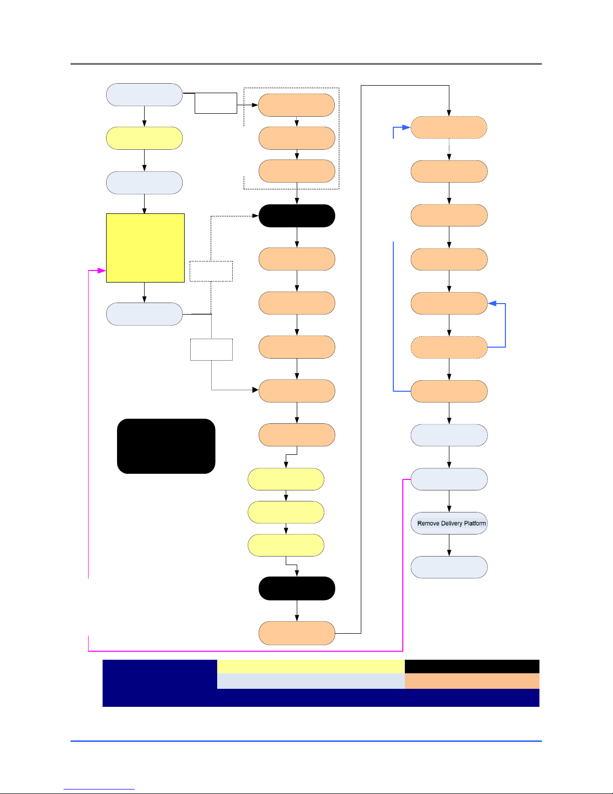
8. NEUROBLATE® SYSTEM PROCEDURE WORKFLOW...................................................................................... 57
8.1. PROCEDURE PRE-PLANNING ............................................................................................................................57
8.1.1. M*Vision Software Start Screen ..........................................................................................................57
8.1.2. Load and Register Image Data within Plan Register Task ...................................................................58
8.1.3. Create Region of Interest (ROI) Volumes within the Plan Volumes Task .............................................61
8.1.4. Create Intended Trajectories within the Trajectory Task .....................................................................63
8.1.5. Saving a Plan........................................................................................................................................65
8.1.6. Opening a Saved Plan ..........................................................................................................................66
8.2. OPERATING ROOM:PRE-PROCEDURE PREPARATION ............................................................................................67
8.2.1. Sterile Probe Delivery Platform ............................................................................................................67
8.2.2. Anesthesia............................................................................................................................................67
8.2.3. Head Fixation.......................................................................................................................................67
8.2.4. Image-Guided Surgery (IGS) System Registration (Non-Sterile) ..........................................................67
8.2.5. Prepping and Sterile Draping for Trajectory Guidance Devices ...........................................................68
8.2.6. Image-Guided Surgery (IGS) Registration - Sterile ...............................................................................68
8.2.7. Laser Delivery Probe (LDP) Platform Attachment ................................................................................68
8.2.7.1. Skull-Mounted Trajectory Devices such as AXiiiS Stereotactic Miniframe ...........................................68
8.2.7.2. Skull Bone Anchor ................................................................................................................................68
8.2.8. Create a Pathway to the Intended Target ...........................................................................................69
8.2.9. Laser Delivery Probe (LDP) Depth Stop and Size Determination..........................................................70
8.2.9.1. AXiiiS Stereotactic Miniframe - Depth Stop and Size ...........................................................................70
8.2.9.2. Skull Bone Anchor such as Monteris Mini-Bolt - Depth Stop and Size..................................................71
8.3. PREP FOR TRANSFER TO MRI...........................................................................................................................74
8.4. INTERFACE PLATFORM (IP) ATTACHMENT/DETACHMENT–TABLE OR ATAMASTABILIZATION SYSTEM............................74
8.5. TRAJECTORY CONFIRMATION AND BEAM FIDUCIAL MARKER DETECTION ..................................................................85
8.5.1. Scan and Register Data in M*Vision using Plan Register Task ............................................................86
8.5.2. Create Region of Interest (ROI) Volumes within Plan Volumes Task....................................................86
8.5.3. Create Trajectories within Trajectories Task for AXiiiS ........................................................................87
8.5.4. Create Trajectories within Plan Trajectories Task – without AXiiiS......................................................87
8.5.5. Identify Ball Marker Selection within the Align Task ...........................................................................88

NeuroBlate® System Instructions for Use
80469 Rev D – Nov 16, 2018
- 4 -
8.6. SELF-TEST,PROBE DRIVER ATTACHMENT AND LDP INSERTION...............................................................................90
8.6.1. Final Trajectory Adjustment in Insert...................................................................................................90
8.6.1.1. AXiiiS Workflow....................................................................................................................................90
8.6.1.2. Non-AXiiiS Workflow............................................................................................................................92
8.6.2. Probe Driver (APD and RPD) Attachment and Connections (if Applicable)..........................................93
8.6.3. Laser Delivery Probe (LDP) Size Selection and Insertion.......................................................................99
8.7. MRI CONFIRMATION OF LDP INSERTION .........................................................................................................110
8.8. THERMAL DELIVERY AND MONITORING IN TREAT WORKFLOW TASK......................................................................113
8.8.1. ENABLE THE MRI FOR REAL TIME TRANSFER.....................................................................................114
8.8.1. Position Thermal Monitoring Planes in M*Vision..............................................................................121
8.8.2. Thermal Sequence Prescription on the MRI .......................................................................................124
8.8.2.1. GE Thermal Sequence Prescription Procedure ...................................................................................125
8.8.2.2. Philips MRI Thermal Sequence Prescription Procedure......................................................................132
8.8.3. Initiate Thermal Monitoring in M*Vision...........................................................................................135
8.8.3.1. For Philips MRI Only (for all other MRI types skip to 8.8.3.2) ............................................................135
8.8.3.2. Initiate Thermal Monitoring for all Other MRI Types.........................................................................137
8.8.3.3. Initiate Delivery of Laser Energy to Tissue .........................................................................................142
9. ELECTRICAL RACK REQUIREMENTS AND TECHNICAL DATA ....................................................................... 150
10. TECHNICAL SUPPORT ................................................................................................................................ 155
11. CONTACT INFORMATION.......................................................................................................................... 156
11.1. DISTRIBUTOR/REP CONTACT: ........................................................................................................................156
11.2. MANUFACTURED BY: ...................................................................................................................................156
12. TIPS AND TROUBLESHOOTING.................................................................................................................. 157
Patent Notice under 35 U.S.C. §287(a): Monteris Medical products and associated processes are subject
to the United States patents and pending applications.
NeuroBlate, Monteris Medical, SideFire, FullFire, AXiiiS, AtamA, AutoLITT, Monteris Mini-Bolt, the M
Logo, the N Logo, the A Logo and M*Vision Pro are trademarks of Monteris Medical. © Copyright
Monteris Medical 2018. All rights reserved.

NeuroBlate® System Instructions for Use
80469 Rev D – Nov 16, 2018
- 5 -
Anesthesia
AtamA
(Head Fixation Setup)
Draping / Sterile Field
AXiiiS Attachment
AXiiiS Trajectory
Alignment
Set Initial Probe Insertion
Depth
Load Image Data
Volume Definition
Trajectory Definition
Load Image Data and
Registration
AXiiiS (Fiducial Marker)
Detection
Set Maximum Probe
Depth (PDP)
System Self Test
Laser Foot Pedal
Check
Adv. Probe Driver (APD)
Attach and Check
Probe Attach, Check and
Insertion
MRI Scan for Probe
Placement
Load Image Data
Adjust
SW Rendered Probe to
Artifact
MRI Real Time Transfer
Setup
Begin Real Time
Measurements
Temperature Calculation
Setup (Ref Points)
Thermal Dose Monitoring
End Lasing
Move Patient from MRI
Bore
Remove Probe and APD
Close Patient
Move APD – Probe
Linear Travel
Move APD – Probe
Rotation
Remove AXiiiS
(Pre) Planning
Next Trajectory
Next Probe Movement - Linear
NeuroBlate
Procedure
Overview
Patient Placement in MRI
MRI Trajectory Confirm
(Wand)
Procedure Flowchart
Color Key
Manipulation of a Monteris Device
MRI Image Acquisition
Surgical Team Patient Management
Software Worflow Steps
Flowchart 1: NeuroBlate® System Procedure Overview
Delivery Platform
(AXiiiS) Attachment
and IGS Alignment
or
Stereotactic System
Alignment and Delivery
Platform (Bolt)
Attachment
AXiiiS
Workflow
Pre-Op or
in Parallel
Mini-Bolt
Workflow

NeuroBlate® System Instructions for Use
80469 Rev D – Nov 16, 2018
- 6 -
1. System Description
1.1. NEUROBLATE®SYSTEM DESCRIPTION
The Monteris NeuroBlate® System enables MRI-guided neurosurgical ablation. The NeuroBlate
System hardware and disposable accessories are outlined in Table 1.1.
Table 1.1: NeuroBlate System Product List
Component
Catalog
Number
Description
Other Information
NeuroBlate System
NB102
For use with Siemens, IMRIS, GE, or Philips MRI
Interface Platform
Resides behind the patient head during
MR thermal imaging to manage the
electronic connections for the Probe
Driver and Laser Delivery Probe as well
as the cooling connection.
MRI Conditional
(1.5T/3.0T)
System Electronics Rack
and Components
A rolling cabinet which resides in an
equipment area adjacent to the MRI
containing the system control
computers, electronic hardware, laser
light source and CO2cooling
components.
MR Unsafe
Control Workstation
containing M*Vision Pro
Software
A system workstation which resides in
the MRI control area and includes a
laser foot pedal, keyboard, mouse and
display for the graphic user interface
MR Unsafe
NeuroBlate Advanced
Probe Driver (APD)
NBD-01
Control device to manage linear
translation and rotational manipulation
of the Laser Probe during the NB
procedure. Attaches to the Interface
Platform and AXiiiS.
MRI Conditional
(1.5T/3.0T)
Sterile
Single Use Only
NeuroBlate Robotic Probe
Driver (RPD)
RPD-01
Lower profile Control device to manage
linear translation and rotational
manipulation of the Laser Probe during
the NB procedure. Attaches to the
Interface Platform and appropriate
bone anchors.
MRI Conditional
(1.5T/3.0T)
Sterile
Single Use Only

NeuroBlate® System Instructions for Use
80469 Rev D – Nov 16, 2018
- 7 -
Component
Catalog
Number
Description
Other Information
SideFire® Optic 3.3
Directional Laser Probe
#000 (133mm)
#00 (154mm)
#1 (175mm)
#2 (196mm)
#3 (217mm)
#4 (238mm)
#5 (259mm)
NBP-000-01
NBP-001-01
NBP-101-01
NBP-201-01
NBP-301-01
NBP-401-01
NBP-501-01
Gas-cooled, directional laser delivery
probe (LDP) used to deliver controlled
energy to the intended target zone.
The appropriate probe length is
determined by the M*Vision software.
3.3mm Outside Diameter
MRI Conditional
(1.5T/3.0T)
Sterile
Single Use Only
FullFire® Optic 3.3
Diffusing Tip Laser Probe
#000 (133mm)
#00 (154mm)
#1 (175mm)
#2 (196mm)
#3 (217mm)
#4 (238mm)
#5 (259mm)
DTP-000-01
DTP-001-01
DTP-101-01
DTP-201-01
DTP-301-01
DTP-401-01
DTP-501-01
Gas-cooled, diffusing laser delivery
probe (LDP) used to deliver thermal
energy in all directions from the probe
tip to the intended target zone.
The appropriate probe length is
determined by the M*Vision software.
3.3mm Outside Diameter
MRI Conditional
(1.5T/3.0T)
Sterile
Single Use Only
FullFire® Optic 2.2
Diffusing Tip Laser Probe
#000 (133mm)
#00 (154mm)
#1 (175mm)
#2 (196mm)
#3 (217mm)
#4 (238mm)
#5 (259mm)
FFS000-01
FFS002-01
FFS122-01
FFS222-01
FFS322-01
FFS422-01
FFS522-01
Smaller Diameter, Gas-cooled, diffusing
laser delivery probe (LDP) used to
deliver thermal energy in all directions
from the probe tip to the intended
target zone.
The appropriate probe length is
determined by the M*Vision software.
2.2mm Outside Diameter
MRI Conditional
(1.5T/3.0T)
Sterile
Single Use Only

NeuroBlate® System Instructions for Use
80469 Rev D – Nov 16, 2018
- 8 -
Monteris Medical also offers an array of optional disposable and reusable devices (Table 1.2)
which can be used for Laser Probe delivery and skull anchoring as well as head stabilization.
These devices are not required for the use of the NeuroBlate System, but have been validated
to work properly with the NeuroBlate System.
Table 1.2: Optional Products Validated for Use with the NeuroBlate System
Item
Catalog
Number
Description
Other Information
AXiiiS® Stereotactic
Miniframe
AX300-01
MRI Visible, Stereotactic Mini-Frame for
trajectory alignment, and guidance of
NeuroBlate Laser Delivery Probe.
MRI Conditional
(1.5T/3.0T)
Sterile
Single Use Only
Instrument Adapter
IA300-01
Set of three reducing tubes (1.9, 2.2,
and 2.6mm) designed to guide
neurosurgical devices (Example: a
biopsy needle) through the AXiiiS
Stereotactic Miniframe Directional
Interface.
MRI Safe
Sterile
Single Use Only
MRI Trajectory Wand
MW300-01
MRI visible, fluid-filled tube, which
when placed into the AXiiiS Stereotactic
Miniframe allows confirmation of AXiiiS
alignment to target along the intended
trajectory.
MRI Safe
Sterile
Single Use Only
Monteris® Mini-Bolt
CMB033
CMB022
The Monteris® Mini-Bolt assembly is
a disposable, rigid skull fixation
device designed to provide a stable
platform to deliver neurosurgical
devices or instruments.
MRI Conditional
(1.5T/3.0T)
Provided Non-Sterile
Single Use Only
AtamA® Stabilization
System
ATB002-XX
MR compatible head fixation device for
patient immobilization and transfer.
MRI Conditional
(1.5T/3.0T)

NeuroBlate® System Instructions for Use
80469 Rev D – Nov 16, 2018
- 9 -
The NeuroBlate System is compatible with only the following 1.5T or 3.0T MRI systems.
•Siemens - minimum software versions VB17, VB19, VD13, VE11
oSymphony (1.5T)
oAvanto (1.5T)
oTrio (3.0T)
oEspree (1.5T)
oVerio (3.0T)
oAera (1.5T)
oSkyra (3.0T)
•IMRIS NEURO II (1.5T) or NEURO III (3.0T) - Siemens MRI software versions listed above
•GE - minimum software version 12.X, 15.X to 26.X
oSigna HDx/HDxT (1.5T & 3.0T)
oOptima MR450/450W (1.5T)
oDiscovery MR750/750W (3.0T)
oSigna Artist (1.5T) software version 26.X - using 16-channel GE Flex Coil
•Philips – software version R3, R4, R5
oAchieva (1.5T & 3.0T)
oIngenia (1.5T and 3.0T)

NeuroBlate® System Instructions for Use
80469 Rev D – Nov 16, 2018
- 10 -
Figures 1.1 and 1.2 below depict the set-up of NeuroBlate System within the MRI suite.
* Note, at the HCP request, the Electronics Rack can also be co-located in the MRI Control Room
Figure 1.1: Typical Layout of the NeuroBlate System within the MRI Suite
Figure 1.2: NeuroBlate Components in the MRI Environment
MRI Scan
Room
*MRI
Equipment
Room
MRI Control
Room
Interface
Platform
Electronics
Rack
Control
Workstation
Laser Delivery Probe inserted into
the Monteris Mini-Bolt
Probe Driver
Mounted on
Interface Platform
Head Stabilized
in AtamA
System

NeuroBlate® System Instructions for Use
80469 Rev D – Nov 16, 2018
- 11 -
1.2. NEUROBLATE OPTIC LASER DELIVERY PROBES &PROBE DRIVER DESCRIPTIONS
1.2.1. Laser Delivery Probes (LDP)
The NeuroBlate System family of Laser Delivery Probes are single-use (disposable) patient
interface components used to deliver laser interstitial thermal therapy. The Probe is considered
MR Conditional at 1.5T and 3T. The Probe allows for gas cooling during simultaneous laser
application and thermal imaging. The LDP’s are available in multiple lengths and configurations
in two outside diameters: 3.3 and 2.2 mm. The appropriate length is determined during clinical
use by the NeuroBlate M*Vision software. The appropriate probe configuration and diameter is
determined by the physician depending on the clinical need.
Figure 1.3: NeuroBlate Laser Delivery Probe
Probe Tip
Probe Depth
Stop
Probe
Connectors
Probe Body
Probe
Connector
Section
Probe Umbilical

NeuroBlate® System Instructions for Use
80469 Rev D – Nov 16, 2018
- 12 -
Figure 1.4: Laser Delivery Probe Body; Inside Ruler/Protective Cover
The LDP assembly (see Figures 1.3, 1.4 and 1.5) is comprised of:
1) Removable Ruler/Protective Cover
2) LDP Tip (Sapphire Capsule)
3) Probe Locking Interface and Depth Stop
4) LDP connectors including Temperature Sensor, Laser Fiber, CO2Cooling, Probe Detection
Figure 1.5: LDP Locking Interface and Depth Stop
The Laser Delivery Probe Locking Interface attaches to the Advanced Probe Driver Follower, the
Robotic Probe Driver Follower, or an appropriate skull anchoring device. To remove the
Ruler/Protective Cover, the green button on the Locking Interface is pressed to release it
(Figure 1.5). The Depth Stop (Figure 1.5) is adjustable (see double arrow in Figure 1.5) to allow
the LDP tip to be set to the desired depth for insertion into the brain.
Probe Ruler/
Protective Cover
Locking Interface
Depth Stop

NeuroBlate® System Instructions for Use
80469 Rev D – Nov 16, 2018
- 13 -
1.2.2. SideFire® Optic 3.3 Directional Laser Probe
Figure 1.6: Detail of the SideFire® Optic 3.3 Directional Laser Probe Tip (SFP)
The SideFire® Optic 3.3 Directional Laser Probe tip (Figure 1.6) is comprised of a clear sapphire
lens and the LDP Shaft. The internal components of the LDP can be visualized through the LDP
lens.
•An optical fiber terminates inside the lens at the Fiber Line tip and emits controlled laser
energy in a uniform direction at approximately 78 degrees from the long axis of the SFP.
•An integrated cooling line circulates CO2 gas inside the LDP tip to cool during laser delivery.
•A fiber optic temperature sensor measures the temperature of the LDP tip and delivers this
information to the M*Vision software.
Probe Shaft
Optical Temperature Sensor
Cooling Tube
Fiber Line Tip
(laser beam exit)
Probe Lens

NeuroBlate® System Instructions for Use
80469 Rev D – Nov 16, 2018
- 14 -
1.2.3. FullFire® Optic Diffusing Tip Laser Probes
Figure 1.7: Detail of the Distal End of the FullFire® Optic Diffusing Tip Laser Probe
The FullFire® Optic 3.3 and smaller diameter FullFire™ Optic 2.2 Diffusing Tip Laser Probes are
comprised of the same components and mechanical interfaces as the SideFire® Optic 3.3
Directional Laser Probe. The FullFire probe is differentiated by laser energy dispersion in all
directions/dimensions (see representative red arrows in Figure 1.7) and emanating from a 6mm
long emission area (Figure 1.7).

NeuroBlate® System Instructions for Use
80469 Rev D – Nov 16, 2018
- 15 -
1.2.4. Laser Delivery Probe Selection
Selection of the SideFire® Optic Directional Laser Probe (SFP) versus the FullFire® Optic
Diffusing Tip Laser Probe should be determined by the size and shape of the intended ablation
area. The SideFire probe provides support for the ablation of irregular shapes based on its
ability to selectively ablate with a directional beam. If the safest trajectory does not place the
LDP near the center of the target area but closer to one edge, SideFire may be the best choice
for focal energy delivery to prevent unwanted heating outside of the target region. The FullFire
probe provides support for the ablation of symmetrical areas with a diffuse beam. The SideFire
probe allows conformal control of the ablation area. FullFire probe may create a concentric
ablation area.
If the target and path to target demands a smaller diameter probe, the FullFire® Optic 2.2 is a
suitable LDP ablation tool. The selection of a 2.2 probe follows the same considerations noted
above. The reduced diameter 2.2 probe achieves target accuracy only if the pathway is first
created to the target with an alignment mandrel.
There may be situations in which both LDP energy emission types (SideFire and FullFire) will be
used in succession to achieve optimal thermal dose conformance to the target area. The
FullFire probe may be used to ablate initially, followed by insertion of the SideFire probe to
ablate additional areas.

NeuroBlate® System Instructions for Use
80469 Rev D – Nov 16, 2018
- 16 -
1.2.5. Advanced Probe Driver (APD) and Robotic Probe Driver (RPD)
Both the (single use) Advanced Probe Driver (APD) and (single use) Robotic Probe Driver (RPD)
are mounted to the NeuroBlate System Interface Platform (IP). The APD follower is designed to
be mounted onto a skull-mounted stereotactic anchoring device. The RPD follower is a lower
profile version of the APD follower designed to adapt to an appropriate skull bone anchor.
Other than the follower assembly, the functionality of APD and RPD is the same. The APD and
RPD Position Feedback Plug (Figure 1.8) connects to the Interface Platform to communicate the
Laser Delivery Probe’s position in the brain to the system user interface. The APD/RPD rotates
or translates (extends or retracts) the NeuroBlate Laser Delivery Probe. The APD/RPD provides
linear translation of up to 40 mm and total rotation of 340°.
The APD and RPD is comprised of two components: the Commander and the Follower (Figure
1.8), connected by an umbilical cable.The RPD uses a shortened version of the Follower as
shown in Figure 1.9. A Rotary Test Adapter is included with the APD and RPD, to be used
during Self-Test to simulate the attachment of Laser Delivery Probe during the procedure.
Figure 1.8: Advanced Probe Driver Components
Rotary
Test Adapter
3 Thermal

NeuroBlate® System Instructions for Use
80469 Rev D – Nov 16, 2018
- 17 -
Figure 1.9: Robotic Probe Driver (RPD) with shortened follower stem
•The APD and RPD Commander can be used to manipulate the Laser Probe (translation and
rotation) during the procedure in two ways:
oManual - the knobs can be manipulated by pressing them in toward the main body
of the Commander and turning (knobs will not turn unless pressed in)
Blue knob controls linear translation
Green knob controls rotation
oRemote – the knobs can be managed from the Control Workstation by manipulating
the software rendered LDP in the graphical user interface (GUI) of the M*Vision
software.
Shortened
Follower

NeuroBlate® System Instructions for Use
80469 Rev D – Nov 16, 2018
- 18 -
•The APD Follower (Figure 1.10) can be mounted to a stereotactic miniframe such as but not
limited to the AXiiiS® Stereotactic Miniframe (see Section 8.6.2 Attach Advanced Probe
Driver (APD) to Interface Platform and AXiiiS) and provides supportive interface to the
Laser Probe during use.
Figure 1.10: Detail of APD Follower
•The RPD requires the use of a locking sleeve for attachment to an appropriate skull
anchoring device.Figure 1.11 illustrates how the RPD and the locking sleeve accessory
attach to a skull bone anchor.
Figure 1.11: Details of RPD Follower and its attachment to a skull bone anchor
Mounting
Interface for
AXiiiS®
Interface for AXiiiS®
Locking Interface
for
Laser Probe
Fully advanced or
(0 mm) position shown
40mm
Translation
(Linear Travel)
± 170°
Rotation
Bone
Anchor

NeuroBlate® System Instructions for Use
80469 Rev D – Nov 16, 2018
- 19 -
1.3. OPERATING MODES
The NeuroBlate System has 2 modes of operation, Active and Standby. These modes are
defined by 5 essential functions the system can provide and more specifically, the state of each
function. The system is in Active mode if at least one Essential Function is activated (shown “in
operation” on the system Control Workstation screen). The five essential functions are:
1. DICOM file transfer from MRI (receive)
2. Probe cooling
3. Probe (Probe Driver) linear and rotary travel
4. Laser Ready (enabled for laser emission) or Laser (laser emission is active)
5. Emergency Stop
a. Disables Probe Cooling, Probe linear and rotary Travel and Laser
b. Sounds alarm
The system is in Active mode if at least one essential function is activated as noted, or at least
one of the following:
•Receiving files through the Ethernet connection
•Probe is cooling
•Probe (via APD or RPD) is in motion (linear or rotary)
•Laser is shown in Ready mode on the Control Workstation screen (enabled for laser
emission)
•Laser is shown as Laser mode on the Control Workstation screen and audible beeping is
heard (laser emission is active)
•Emergency Stop has been pressed/engaged
The system is in Standby mode if the system is fully turned on but none of the Essential
Functions are in active mode, meaning:
•Not receiving any files through Ethernet connections
•Probe is not cooling (or not commanded to cool)
•Probe is not in motion (or not commanded to move in either linear or rotary axis)
•Laser is in “Standby” mode (or disabled)
•Emergency Stop has not been engaged

NeuroBlate® System Instructions for Use
80469 Rev D – Nov 16, 2018
- 20 -
2. Indications for Use
The Monteris Medical NeuroBlate System is indicated for use to ablate, necrotize, or coagulate
intracranial soft tissue, including brain structures, through interstitial irradiation or thermal
therapy in medicine and surgery in the discipline of neurosurgery with 1064 nm lasers.
The Monteris Medical NeuroBlate System is intended for planning and monitoring thermal
therapies under MRI visualization. It provides MRI-based trajectory planning assistance for the
stereotaxic placement of MRI compatible (conditional) NeuroBlate Laser Delivery Probes. It also
provides near real-time thermographic analysis of selected MRI images.
When interpreted by a trained physician, this System provides information that may be useful
in the determination or assessment of thermal therapy. Patient management decisions should
not be made solely on the basis of the NeuroBlate System analysis.
Table of contents
Popular Medical Equipment manuals by other brands

Supera
Supera Pureline M6000 Operator's manual

Coopers of Stortford
Coopers of Stortford F890 Instructions for use

Winco
Winco HOME CARE CLINER Owner's operating and maintenance manual

Cardioline
Cardioline DELTA 1 Plus user manual

Joerns
Joerns HPL400 user manual

Agilent Technologies
Agilent Technologies M1205A V26 Service guide