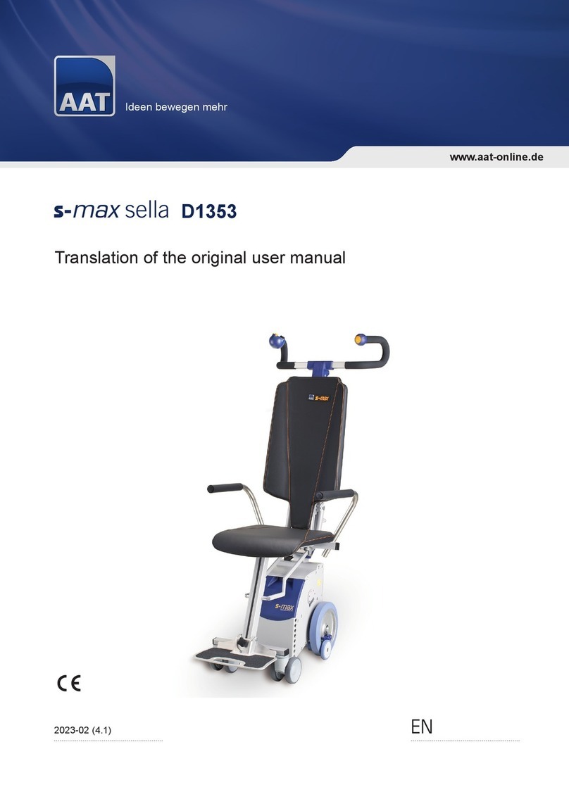
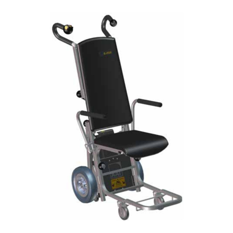
AAT s-max aviation D1611 Installation and operating instructions

www.aat-online.de
Ideen bewegen mehr
EN2021-06 (1.1)
Translation of the original user manual
aviation D1611

2
Spare parts
Repair processing
Technical information
Product seminars
Showroom & exhibition devices
Re-use
Complaints
Rental devices
With our professional service concept
we at AAT prove once again our high
claim of quality and o er our clients an
all-inclusive package.
We are at your service!
AAT service concept
Customer service at its best
AAT Alber Antriebstechnik GmbH
Ehestetter Weg 11 · 72458 Albstadt · Germany
Phone: +49.(0) 74 31.12 95-0
Fax: +49.(0) 74 31.12 95-35
Assembly Team
Phone +49.(0) 74 31.12 95-555
Phone +49.(0) 74 31.12 95-557
Fax +49.(0) 74 31.12 95-558
E-Mail [email protected]
New devices
Phone +49.(0) 74 31.12 95-110
Phone +49.(0) 74 31.12 95-125
Fax +49.(0) 74 31.12 95-35
E-Mail [email protected]
Head offi ce
Phone +49.(0) 74 31.12 95-0
E-Mail [email protected]
Web www.aat-online.de
Service and repairs
Phone +49.(0) 74 31.12 95-550
Phone +49.(0) 74 31.12 95-552
Fax +49.(0) 74 31.12 95-540
E-Mail [email protected]

3
The product is state of the art and complies with the associated technical safety requirements.
Nevertheless, a low level of residual risks cannot be ruled out. Please observe the safety instructions
to this end.
All serious incidents occurring in relation to the device must be reported to the manufacturer and to the
competent authority of the Member State where the user and/or occupant is established.
WARNING
Failure to observe this user manual, in particular the safety instructions, can lead to defects in the
s-max and endanger the operator and the occupant, as well as a ect it in its proper function! There is
an increased risk of injury! In the event of an infringement, claims for warranty and liability are excluded!
People with visual and reading impairments or intellectual disabilities should print out the user
manual available on the website in enlarged letters or have this manual read to them, if necessary.
On our homepage, you will also nd all safety-related changes which have been made to the user
manual. These versions with details of the production period of the product are obtainable at:
www.aat-online.de/de/bda/s-max

4
Table of Contents
1 Symbols and safety instructions . . . . . . . . . . . . . . . . . . . . . . . . . . . . . . . . . .5
2 Explanation of the symbols on the packaging . . . . . . . . . . . . . . . . . . . . . . . . . . .6
3 Explanation of the symbols on the device . . . . . . . . . . . . . . . . . . . . . . . . . . . . .7
4 Product description . . . . . . . . . . . . . . . . . . . . . . . . . . . . . . . . . . . . . . . . .8
4.1 Device overview . . . . . . . . . . . . . . . . . . . . . . . . . . . . . . . . . . . . . . . . . . . .8
4.2 Overview of type plate incl. serial number . . . . . . . . . . . . . . . . . . . . . . . . . . . . . .10
4.3 Intended purpose . . . . . . . . . . . . . . . . . . . . . . . . . . . . . . . . . . . . . . . . . . 10
4.4 Intended patient population . . . . . . . . . . . . . . . . . . . . . . . . . . . . . . . . . . . . . 10
4.5 Medical requirements and indication . . . . . . . . . . . . . . . . . . . . . . . . . . . . . . . . 11
4.6 Contraindications and restrictions . . . . . . . . . . . . . . . . . . . . . . . . . . . . . . . . . . 11
4.7 User group . . . . . . . . . . . . . . . . . . . . . . . . . . . . . . . . . . . . . . . . . . . . . . 11
4.8 Technical data . . . . . . . . . . . . . . . . . . . . . . . . . . . . . . . . . . . . . . . . . . . . 12
4.9 Dimensional drawing. . . . . . . . . . . . . . . . . . . . . . . . . . . . . . . . . . . . . . . . .13
4.10 Scope of delivery . . . . . . . . . . . . . . . . . . . . . . . . . . . . . . . . . . . . . . . . . . 14
4.11 Accessories . . . . . . . . . . . . . . . . . . . . . . . . . . . . . . . . . . . . . . . . . . . . . 14
5 Assembly . . . . . . . . . . . . . . . . . . . . . . . . . . . . . . . . . . . . . . . . . . . . . . 15
5.1 Handle unit. . . . . . . . . . . . . . . . . . . . . . . . . . . . . . . . . . . . . . . . . . . . . .15
5.2 Battery pack . . . . . . . . . . . . . . . . . . . . . . . . . . . . . . . . . . . . . . . . . . . . . 15
6 Starting up . . . . . . . . . . . . . . . . . . . . . . . . . . . . . . . . . . . . . . . . . . . . . 16
6.1 Adjusting the handles to the correct height . . . . . . . . . . . . . . . . . . . . . . . . . . . . . 16
6.2 Transverse adjustment of handle . . . . . . . . . . . . . . . . . . . . . . . . . . . . . . . . . . 16
6.3 Switching on the device . . . . . . . . . . . . . . . . . . . . . . . . . . . . . . . . . . . . . . . 17
6.4 Neutral position . . . . . . . . . . . . . . . . . . . . . . . . . . . . . . . . . . . . . . . . . . . 17
6.5 Checking the safety brakes . . . . . . . . . . . . . . . . . . . . . . . . . . . . . . . . . . . . . 18
6.6 Single-step mode . . . . . . . . . . . . . . . . . . . . . . . . . . . . . . . . . . . . . . . . . . 18
6.7 ComfortStep . . . . . . . . . . . . . . . . . . . . . . . . . . . . . . . . . . . . . . . . . . . . . 19
6.8 Checking battery capacity . . . . . . . . . . . . . . . . . . . . . . . . . . . . . . . . . . . . . . 19
7 Operation . . . . . . . . . . . . . . . . . . . . . . . . . . . . . . . . . . . . . . . . . . . . . . 20
7.1 Occupant taking a seat . . . . . . . . . . . . . . . . . . . . . . . . . . . . . . . . . . . . . . . 21
7.2 Moving on level ground / overcoming obstacles . . . . . . . . . . . . . . . . . . . . . . . . . . .23
7.3 Tilting the stair climbing system . . . . . . . . . . . . . . . . . . . . . . . . . . . . . . . . . . . 23
7.4 Moving on slopes . . . . . . . . . . . . . . . . . . . . . . . . . . . . . . . . . . . . . . . . . . 24
7.5 Climbing stairs - Upwards . . . . . . . . . . . . . . . . . . . . . . . . . . . . . . . . . . . . . . 25
7.6 Climbing stairs - Downwards . . . . . . . . . . . . . . . . . . . . . . . . . . . . . . . . . . . . 26
7.7 Laying down on stairs / emergency stop function . . . . . . . . . . . . . . . . . . . . . . . . . . 27
7.8 Parking. . . . . . . . . . . . . . . . . . . . . . . . . . . . . . . . . . . . . . . . . . . . . . . .27
7.9 Transportation . . . . . . . . . . . . . . . . . . . . . . . . . . . . . . . . . . . . . . . . . . . . 28
8 Care and maintenance . . . . . . . . . . . . . . . . . . . . . . . . . . . . . . . . . . . . . . . 28
8.1 Battery and charger . . . . . . . . . . . . . . . . . . . . . . . . . . . . . . . . . . . . . . . . . 29
8.2 Checking brake linings and climbing feet linings . . . . . . . . . . . . . . . . . . . . . . . . . . 31
8.3 Cleaning and disinfection . . . . . . . . . . . . . . . . . . . . . . . . . . . . . . . . . . . . . . 32
8.4 Replacing fuses . . . . . . . . . . . . . . . . . . . . . . . . . . . . . . . . . . . . . . . . . . . 33
8.5 Technical safety testing . . . . . . . . . . . . . . . . . . . . . . . . . . . . . . . . . . . . . . . 34
8.6 Disposal . . . . . . . . . . . . . . . . . . . . . . . . . . . . . . . . . . . . . . . . . . . . . . . 34
8.7 Long-term storage . . . . . . . . . . . . . . . . . . . . . . . . . . . . . . . . . . . . . . . . . . 35
8.8 Fault conditions and troubleshooting . . . . . . . . . . . . . . . . . . . . . . . . . . . . . . . . 35
9 Warranty and liability. . . . . . . . . . . . . . . . . . . . . . . . . . . . . . . . . . . . . . . .37
10 Recalls and corrective actions . . . . . . . . . . . . . . . . . . . . . . . . . . . . . . . . . . 37

5
1 Symbols and safety instructions
DANGER - Imminent DANGER
If not avoided, this will result in death or severe bodily injuries!
WARNING - Possibly imminent DANGER
If not avoided, this may result in death or severe bodily injuries!
CAUTION - Possible imminent danger or harmful situation
If not avoided, this may result in minor bodily injuries or damage to property!
iNOTE - Information by the manufacturer
General safety instructions
iNOTE
If you have a visual disability, this user manual can be downloaded at:
www.aat-online.de/de/bda/s-max.
Read the user manual prior to start-up and observe the warning notices and safety instructions.
In the event of reading disabilities, cover training content in more depth verbally.
The user manual must be kept in a safe place after reading through it.
It does not consist exclusively of ame retardant substances. Keep the device away from sources of
ignition.
The s-max may interfere with highly sensitive electromagnetic elds of other electronic devices
(e.g. anti-theft devices).
Stability tests were performed under laboratory conditions. The s-max may behave dierently under
real conditions compared to laboratory tests.
Training may only be carried out by the manufacturer, the AAT eld sta or the qualied specialist shop.

6
Symbol Explanation
Handle with care
The packaging including the product must be handled with special care.
Protect from moisture
Protect the packaging including the product from overly high air humidity.
Cover during storage. If necessary, cover thoroughly with tarpaulins.
Caution fragile
Handle the packaging including the product carefully and never allow it to fall.
This way up
The packaging must be stored and transported in such a way that the arrows
point upwards at all times. Any failure to comply with this rule, such as rolling
or tilting the package, must be avoided.
2 Explanation of the symbols on the packaging
CAUTION
External heat sources may cause the surface temperature to rise (e.g. sunlight)!
Do not touch the aected surfaces in this case to avoid burns!
WARNING
Never reach into rotating/moving parts to avoid crushing.
DANGER
The s-max must not be operated in the case of severe visual impairment and/or blindness!
Do not exceed the total permissible weight and the max. person weight, as this may lead to defects or
an overload the s-max!
Do not use in rain, wet conditions, snow or black ice to avoid slipping due to the reduced braking
eect!
Do not use on escalators or travellators to avoid injuries from falling, the occupant tipping out and
damage to property!
The operability of the s-max may be inuenced by electromagnetic elds (e.g. by mobile phones,
electric generators, or high-voltage sources)!
Do not store near medical devices, for example with a life support function, and diagnostic devices, as
these may malfunction!

7
3 Explanation of the symbols on the device
Symbol Explanation
CE marking
Position: Type plate
The product complies with the relevant provisions of the
EC Regulation EC 2017/745 (MDR)
20XX
Date of manufacture
Position: Type plate
Indicates the year the medical device was manufactured.
Manufacturer
Position: Type plate
Shows the manufacturer of the medical device (AAT Alber Antriebstechnik GmbH)
SN
SN
Position: Type plate
Serial number of the product e.g. D1611XXXXXX
Medical Device
Position: Type plate
Observe the user manual!
Position: Type plate
The user manual must be observed! (www.aat-online.de)
Attention!
Position: Type plate
Refers to the need for the user to review the user manual and important safety-related
information. Position: Type plate
Barcode
Position: Type plate
Contains the AAT serial number
Technical safety test badge
(refer to chapter Technical safety test)
Position: Left side of drive unit
Informs about the due date of the next technical safety test
Adhesive label on the drive unit (for D1611)
The device may only be operated by trained persons!
Max. load 160 kg.
Observe the user manual!
Check the safety brakes before use according to the user manual!
Adhesive label UP / DOWN
Position: UP/DOWN switch on the control panel
Refers to the direction of travel
(refer to chapter “Climbing stairs upwards and downwards”)

8
4 Product description
4.1 Device overview
17
1
14
15
13
7
3
4
2
19
18
5
8
9
10
11
12
6
16
19

9
Handle
Locking wheel
Control panel
Locking knob
Stanchion tube
Locking knob
Battery pack unlocking
Battery pack
Climbing unit
Wheel
Climbing leg with climbing feet and turning mechanism
Safety brake
Castor
Bracket for extending the footrest
Foot support
Foot strap
LED
Transport chair
Harness system
UP/DOWN switch
Speed control
Safety chip for immobiliser
ON/OFF switch
i
Manufacturer’s information:
For a simpli ed assignment of
the individual components, the
numbers listed here are cited
in full for the rst time in the
following chapters.

10
4.2 Overview of type plate incl. serial number
4.3 Intended purpose
4.4 Intended patient population
The stair climbers are guided manually and are operated by an operator.
They make it possible to transport a single person with reduced mobility safely over stairs, upwards and
downwards. The products have been designed for indoor and outdoor use, and moving on spiral stairs
and slopes is possible, too.
The intended patient population includes all persons who are able to sit independently and have a
maximum body weight corresponding to the technical specication of the respective model and variant
(max. 160 kg for the s-max D1601).
Product / Model
Max. load
Batteries
Charging voltage
Operating voltage
Rated power of motor
Barcode (refer to chapter 3)
Serial number (refer to chapter 3)
Symbols (refer to chapter 3)
Manufacturer address

11
4.5 Medical requirements and indication
4.6 Contraindications and restrictions
4.7 User group
The patients must be able to sit independently. Secure persons who cannot sit upright unaided with belts
(refer to accessories) to prevent the occupant from falling out!
The manually guided stair climber assists the accompanying person while transporting the patient over
stairs or slopes, upwards and downwards. The use of the stair climber is intended for patients who
are not able to move by themselves and accompanying persons who do not have sucient physical
endurance and strength to move the patient over stairs or slopes. The s-max aviation is used to transport
patients into an aircraft.
The stair climbers must not be used if:
• the operator has obtained no training/instruction for the product!
• the operator is below the age of 16!
• there is no supervision for minors of at least 16 years of age!
• the operator is not physically and mentally able to operate the stair climber safely!
• more than one person shall be transported simultaneously!
• the person to be transported cannot sit upright unaided!
• the operator does not have adequate eyesight!
• the braking eect is reduced due to rain, wet conditions, snow or black ice!
• the one-side and/or two-side braking eect of stair climber does not set in!
• escalators or travelators shall be overcome!
• medical devices with e.g. a life support function, and diagnostic devices are in the proximity!
• it is not used according to the intended use!
The stair climbers are intended for use by ground handling personnel.
Users are trained in the use of the device by means of a training course.

12
4.8 Technical data
WARNING - Do not exceed the total permissible weight and the max. person weight, as this
may lead to defects or an overload the s-max!
NOTE - Observe the technical data.
i
Technology s-max D1611
Own weight
Climbing unit = 33.6 kg
Handle unit = 3.4 kg
Battery pack = 3.1 kg
Total weight without battery = 37 kg
Total permissible weight 200 kg
Maximum person weight 160 kg
Climbing speed in steps / min 8 - 23, continuously adjustable 1)
Range per battery charge for an
average person weight of 75 kg Approx. 18 oors (approx. 270 steps)
Range per battery charge for a max.
person weight of 160 kg (person) Approx. 9 oors (approx. 135 steps)
Maximum height of step 225 mm
Min. depth of step 140 mm 2)
Required step width Width s-max aviation with transport chair + 100 mm
Minimum platform size 1350 mm x 1350 mm
Min. outer radius from step depth 140 mm
(spiral staircases) 1350 mm
Max. slope of the stairs 61.2°
Min. step depth in mm (spiral staircases) 140 mm
Batteries 2 x 12 V / 3.3 Ah (gas-tight)
Direct current motor 24 V / 275 W
Switching force UP/DOWN switch 3 - 8 N
Direct operating forces 3 - 8 N
Sound pressure level < 70 dB
Storing/operating temperature: Device -40 °C to +65 °C / -25 °C to +50 °C
Storing/operating temperature: Battery -25 °C to +65 °C / -25 °C to +50 °C 3)
Battery charging temperature 0 °C to + 40 °C
Altitude application range (sea level) < 3000 m above sea level
Vibration information The weighted RMS value of acceleration, to which the upper body
is subjected, is typically below 2.5 m/s2.
Adhesive label with serial number Battery pack drawer
IP protection class IPX4
Classication according to ISO 7176-28:2012 Type C
1) With activated ComfortStep, the climbing speed and the range are reduced. The range also depends on the weight of the occupant.
2) Any steps of a smaller depth may not be travelled as in this case it is no longer possible for the wheel to be set down safely.
3) At temperatures below 0 °C the performance of the battery pack will decrease; therefore we recommend a storage temperature of at least 0 °C.

13
4.9 Dimensional drawing
>315-1000
Normen im Zeichnungsfel d vorrangig
RoHS & REACH Compliant
Artikelnummer
DIN ISO 1302
DIN ISO 2768-m K
EhestetterWeg 11
D-72458Albstadt
Tel.:07431/1295-0
Fax:07431/1295-36
www.aat-online.de
Rauheit
Reihe 3
AAT AlberAn triebstechnikGmbH
Status
Revision
Maßstab
+0,3
-0,3
kanten DIN ISO 13715
Werkstück-
Oberfläche
BL.
Benennung
Baugruppe
Zeichnungsnummer
Toleranzen
NameDatum
Werkstoff
gepr.
bearb.
±0,1
±0,2
±0,3
±0,5
±0,8
DatumÄnderung Name
>0,5-6
Zust.
>6-30
>30-120
>120-315
Ers. für
030780
D1601 + U3 Airport aviation
Steigerhöhung 250mm Airport
In Bearbeitung
1
Benutzerdefini
e
1
In Bearbeitung
Kramer
17.06.2021
i
e
h2
max. 1684
d
a
min. 1195
Maße nach ISO 7176-15
a Winkel der Sitzfläche 6°
b effektive Sitztiefe 380mm
c effektive Sitzbreite 340mm
d Höhe der Sitzfläche an der vorderen Kante 507mm
e Rückenlehnenwinkel 16°
f Rückenlehnenhöhe 615mm
g Abstand der Fußstütze zur Sitzfläche 352mm
h1 Gesamtlänge m. Fußstütze min. 1051mm
h2 Gesamtlänge m. Fußstütze max. 1184mm
i Gesamtbreite 468mm
k Länge zusammengeklappt -
l Breite zusammengeklappt -
m Höhe zusammengeklappt -
n Winkel Fußstütze zu Sitzfläche 0°
o Abstand Armauflage zum Sitz mm
minimaler Wenderadius ca. 1000mm
379
c
f
n
b
g
h1
Für diese technische Unterlage behalten wir uns alle Rechte nach DIN 34 vor.
Dimensions according to ISO 7176-15
a Seat angle 6°
bEective seat depth 380 mm
cEective seat width 340 mm
d Seat height at the front edge 507 mm
e Backrest angle 16°
f Backrest height 615 mm
g Distance between footrest and seat 352 mm
h1 Total length w. footrest min. 1051 mm
h2 Total length w. footrest max. 1184 mm
i Total width 468 mm
k Length folded -
l Width folded -
m Height folded -
n Angle of footrest to seating surface 0°
o Distance of armrest to seat mm
Minimum turning radius Approx. 1000 mm

14
4.10 Scope of delivery
Climbing unit
Transport chair with foot strap / harness system
Handle unit
Battery pack
Charger incl. instructions
4.11 Accessories
Universal step
Dash 8 adaptation
NOTE - Only use AAT Alber Antriebstechnik GmbH accessories.
i
Headrest
Armrests
ART/SAAB adaptation
Battery pack
Motor vehicle voltage converter

15
5 Assembly
5.1 Handle unit
WARNING - The handle unit must be securely xed with the locking screw so that it is safely
joined to the climbing unit!
WARNING - Plug-in contacts must be dry!
A 9-pin sub-D coupling in the receptacle provides the electrical connection.
Connect the handle unit and
the climbing unit to each
other.
»Control panel on the right!
Secure the connection with
locking knob for stanchion
tube. Both units must have
been securely joined.
5.2 Battery pack
WARNING - The battery pack must be xed and locked to prevent immediate detachment!
Assembly. Insert the battery
pack into the opening
provided in the climbing unit.
»The battery locking device
is activated automatically.
Disassembly. Release the
locking device.
»Press the release button on
the climbing unit downwards,
then pull out the battery
pack.
i
i
Disassembly:
Switch s-max aviation off
and proceed in reverse
order.

16
6.1 Adjusting the handles to the correct height
NOTE - To avoid malfunctions or defects, store the s-max aviation in a frost-free environment for
at least one hour prior to start-up.
NOTE - Press UP/DOWN switch only a few seconds after switching on!
6 Starting up
WARNING - The handle must have been securely xed with the locking screw so that the
handle adjustment does not change directly!
CAUTION - Pay attention to the pinch point at the groove opening to avoid injuries!
Extract the handle to shoulder
height.
Tighten the locking screw
clockwise.
6.2 Transverse adjustment of handle
Turn the locking screw
for transverse adjustment
counterclockwise.
Move the handle in the
desired direction.
Tighten the locking screw
clockwise.
On very narrow stairs, the handle might bump. In these cases, adjust the handle in the transverse
direction.
i
i
Turn the locking screw
for height adjustment
counterclockwise.

17
6.4 Neutral position
Move the climbing leg to
neutral position by keeping
the UP/DOWN switch
pressed.
»If the single-step mode
(refer to chapter 6.6) has
been activated, the climbing
leg is automatically stopped
in neutral position!
Correct. Incorrect!
Insert the safety chip for the
immobiliser.
»The safety chip must snap
in!
Switch the s-max on via the
ON/OFF switch .
6.3 Switching on the device

18
6.5 Checking the safety brakes
DANGER - If there is only a one-sided braking e ect or no braking e ect, do not use the s-max
aviation, to avoid falling from the stairs. Notify the manufacturer, the AAT eld service, or the
authorised specialist dealer!
WARNING - Check safety brakes without occupant!
Tilting the s-max aviation
»Test the safety brakes
before every journey.
Test: the s-max cannot be
rolled forwards, but only
backwards = safety brakes
active.
i
Recommendation by
the manufacturer:
as an aid, support foot
on the drive housing to
tilt the s-max backwards.
For a detailed procedure,
refer to chapter 8.3.
Single-step mode
Deactivate / Activate.
LED is lit = single-step mode
activated!
If you do not need the
single-step mode, you can
switch it o manually on the
membrane keypad.
» LED is not lit = single-step
mode deactivated!
i
Manufacturer’s
recommendation:
Only deactivate the
single-step mode, if the
operator is able to handle
the s-max aviation safely.
DANGER - With the single-step mode deactivated, it is essential to ensure correct operation,
otherwise the s-max aviation may slip!
6.6 Single-step mode

19
6.7 ComfortStep
Deactivate / Activate.
»LED is lit = ComfortStep
activated!
»This ensures a gentle and
thus more comfortable
climbing procedure.
If you do not need
ComfortStep, you can
switch it o manually on the
membrane keypad.
» LED is not lit =
ComfortStep deactivated!
Manufacturer’s
information:
Each time the device is
switched on again, the
memory function plays
back the last setting
used.
i
NOTE - If an adjustment of the step height is to be made, please contact the AAT eld service
or the manufacturer AAT Alber Antriebstechnik GmbH!
6.8 Checking battery capacity
Battery indicator
Green = full
Battery indicator
Yellow = low
» Charge battery.
Red = empty
» Charge battery.
» Warning tone every 12 sec!
»The capacity of the battery
will last for max. 20 - 35
steps!
i

20
7 Operation
DANGER - Operation only by a trained person who is physically and mentally capable of
operating the s-max safely!
DANGER - Do not allow any persons to stay in the danger zone underneath the s-max!
DANGER - Check the safety brakes before each use! (Refer to chapter 6.5)
WARNING - Wear anti-slip footwear to avoid slipping on the stairs.
WARNING - Always operate with both hands to avoid dangerous situations and to ensure a safe
climbing procedure!
WARNING - Do not travel wet, slippery, or waxed stairs to avoid falls! Carpet surfaces must be
non-slip.
WARNING - The arms must not hang down on the sides or be strongly exed in an uncontrolled
manner. Rest the arms on the armrests or thighs!
WARNING - Secure persons who cannot sit upright unaided with belts (refer to accessories -
chapter 4.11) to prevent the occupant from falling out!
NOTE - Practise without occupant and in the single-step mode.
NOTE - Note the depth of the step and its condition! Risk of falling!
NOTE - Press UP/DOWN switch only a few seconds after switching on!
NOTE - When using seat supports (cushions, etc.), ensure that the occupant is securely seated
to prevent the occupant from slipping or falling out.
i
i
i
i
Table of contents
Other AAT Mobility Aid manuals
Popular Mobility Aid manuals by other brands

iWALKFree
iWALKFree iWALK 2.0 user guide

HAUL MASTER
HAUL MASTER 90018 Assembly and operating instructions

Rifton
Rifton K320 TRAM product manual

Invacare
Invacare Spartan 65420 Installation and operating instructions

Direct Healthcare Group
Direct Healthcare Group SystemRoMedic Rowalker400 manual

essential
essential W1700-14 user manual

SALJOL
SALJOL Carbon Rollator Series user manual

MOK
MOK ALJ-009A-GRAY FRAME user guide

Vitea Care
Vitea Care CARTER Instructions for use

Medic Therapeutics
Medic Therapeutics 002-703 instruction manual

TOPRO
TOPRO Troja Classic Instructions for use

Formula baby
Formula baby Trotteur Fun 2 Instructions for use