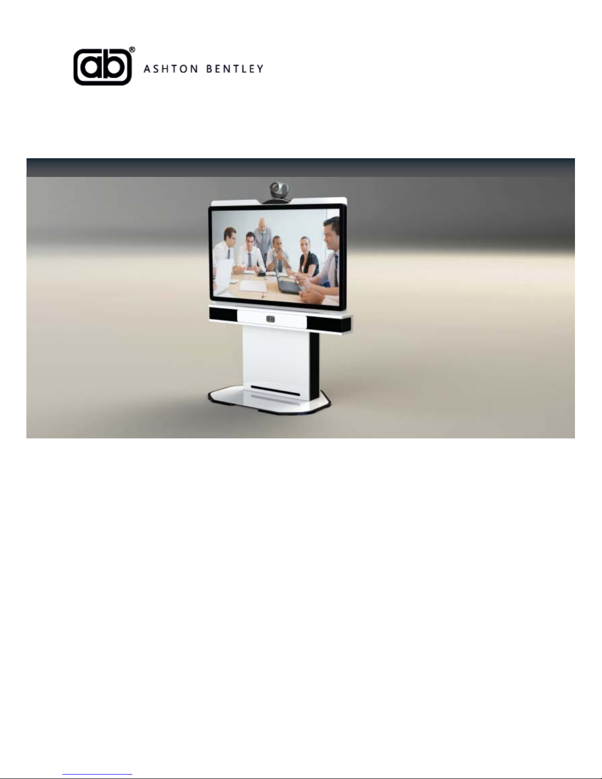
ab Connect one55 Operating manual

User and Installation Manual
“walk in and work”
Connect one55

Document Index
Welcome
Trademark and Patents I
Thank you & Overview II
Important Safety Instruc ons IV
Conven ons Used In This Guide V
Icons Used In This Guide V
Typographic Conven ons V
System Requirements VI
Sec on 1: Product Packaging 0
1.A Connect one55 Packaging Overview 1
1.B Addi onal Equipment Packaging 2
1.C Codec Cables Sets 2
1.D Notes & Warnings 2
Sec on 2: Product Placement 3
2.A Considera ons 4
2.B Product Dimensions 4
2.C Viewing Angles 4
2.D Base Confi gura ons 4
2.E Wall Fixing And Security 5
2.F Room Ligh ng 5
2.G Room Acous cs 5
2.H Manual Handling 5
2.I Power/Data Requirements 5
2.J AC Power 6
2.K Networking 6
Sec on 3: Product Assembly 7
3.A Product Assembly 8
3.B Typographical Conven ons 8
3.C Important Assembly Safety Informa on 8
Sec on 3.1: Wall Fixing Safety & Prepara on 10
3.1.A Prepara on And Safety 11
3.1.B Bracket Adjustment 11
3.1.C Marking fi xing posi ons 12
3.1.D Fixing hole loca ons 12
3.1.E Drilling Holes 12
3.1.F Bracket Adjustment 13
3.1.G Loca ng The System 13
3.1.H Securing The System 14
3.1.I Finer Adjustments 14
Sec on 4: System Wiring 15
4.A AB Velcro Cable Tie Quickstart Guide 16
4.B AB Velcro Cable Tie Posi ons 16
4.C AB Velcro Cable Tie Installa on 16
4.D Wiring Kits & Schema cs 17
4.E Core Cable Kit 17
Sec on 5: Display Panel Connec vity 19
5.A Display Panel Connec vity 20
5.B VGA - Direct Data Input 21
5.C M12 Display Video And Power 22
5.D DVI - Codec and Camera Video 23
5.E HDMI - Data via Codec input 24
www.ashtonbentley.com
Doc No: ABC-506-040738-9905 Rev1

Ashton Bentley Connect one55 User and Installa on Manual
Sec on 6: Loudspeaker Connec vity 26
6.A Audio Connec on 27
6.B Power Connec on 28
6.C Stereo Loudspeaker Connec vity 29
Sec on 7: Camera & Codec Connec vity 30
7.A Camera Connec vity 31
7.B Codec Connec vity 31
7.C Wiring Schema cs 31
Sec on 8: aboxTM 33
8.A Overview 34
8.B aboxTM Default Se ng 34
8.C aboxTM Connec vity Panel 35
8.D aboxTM Installa on 36
8.E aboxTM Rear Panel 36
Sec on 9: Interface-sTM 37
9.A interface-sTM Overview 38
9.B interface-sTM Instruc ons 39
9.C Posi on And Placement 39
9.D interface-sTM Connec vity 40
Sec on 10: interface Bu on Func onality 41
10.A Bu on Panel Overview 42
10.B Presenta on Mode 43
10.C Videoconferencing Mode 44
10.D System Power Off 45
10.E Auxiliary Device Switching 45
10.F Volume Control 46
10.G Mute 46
Sec on 11: Ini al Power Up 48
11.A Powering Up and Star ng Sequence 49
11.B Start Up Messaging: 50
11.C Interface Ini al Power Up 51
11.D Camera
Sec on 12: abox setup 53
12.A Ini al Power Up 54
12.B Boot Sequence Complete 54
12.C Accessing Main Menu 54
12.D Main Menu Structure 54
12.E Menu Naviga on 55
12.F Select Codec Menu 55
12.G Choosing The Correct Codec 55
12.H Confi rming Selec on 55
12.I Saving Selec on And Reboo ng 55
Sec on 13: On Screen Error Messages 56
13.A On Screen Error Messages 57-58

Sec on 14: Warranty Informa on 59
14.A Warranty Overview 60
14.B First Year Advance Replacement 60
14.C Process 61
14.D Years 2&3 Return To Base, Return and Replace 61
14.E Process 62
14.F Extended 3 Year Warranty 62
14.G Extended 5 Year Warranty 62
Sec on 15: Environmental & Regulatory Informa on 63
15.A Environmental 64
15.B Regulatory Informa on 65-66
Sec on 16: Technical Data 67
15.A High Defi ni on Display 67
15.B Stereo Loudspeaker Bar 68
15.C Table Connec vity Box 68
15.D Receiver/Processor/Controller – aboxTM 68
15.E Confi gura ons 68
15.F General 68
15.G Dimensions 68
Appendix 69
A Product Range 70-71
www.ashtonbentley.com
Doc No: ABC-506-040738-9905 Rev1

Welcome

www.ashtonbentley.com
Doc No: ABC-506-040738-9905 Rev1
© 2016 Ashton Bentley Concepts. All rights reserved.
Ashton Bentley Concepts.
Warnford Court
29 Throgmorton Street
London, EC2N 2AT
No part of this document may be reproduced or transmi ed in any form or by any means, electronic or
mechanical, for any purpose, without the express wri en permission of Ashton Bentley Concepts. Under
the law, reproducing includes transla ng into another language or format.
As between the par es, Ashton Bentley Concepts retains tle to and ownership of all proprietary rights
with respect to the so ware contained within its products. The so ware is protected by copyright laws and
interna onal treaty provision. Therefore, you must treat the so ware like any other copyrighted material
(e.g., a book or sound recording).
Every eff ort has been made to ensure that the informa on in this manual is accurate. Ashton Bentley
Concepts is not responsible for prin ng or clerical errors. Informa on in this document is subject to change
without no ce.
Trademark Informa on
Ashton Bentley® and the names and marks associated with Ashton Bentley Concept’s products are
trademarks and/or service marks of Ashton Bentley Concepts, and are registered and/or common law
marks in the United Kingdom and various other countries. All other trademarks are property of their
respec ve owners.
Patent Informa on
The accompanying product is protected by one or more UK, EU, US and foreign patents and/or pending
patent applica ons held by Ashton Bentley Concepts.

Ashton Bentley Connect one55 User and Administrator Guide
II
Thank you
Thank you for choosing the Ashton Bentley Connect one55. In this user manual you will fi nd everything you
need to quickly set up and operate your new conferencing system.
Please be sure to verify with your system administrator that your network is prepared and confi gured
correctly prior to installing and using your Connect one55. These requirements are outlined in this guide. It
is important that you read the Parts List, and the Safety No ces sec on in this guide before you begin using
the system.
Overview
The Ashton Bentley range of products provide unique, simple to assemble turnkey solu ons for presenta on,
videoconferencing and telepresence applica ons that can be assembled and set to work in minutes by
anyone without experience or the assistance of specialists.
Ashton Bentley products are supplied as a complete, out of the box, fully working solu ons which are not
complex to put together and set to work.
Ashton Bentley provide unique product solu ons that enable you to “walk in and work”
This document describes how to assemble and confi gure the Ashton Bentley Connect one55.

Before we begin

IV
Important Safety Instruc ons
When using your Ashton Bentley equipment, the following safety precau ons should always be
followed to reduce the risk of fi re, electric shock or injury to people.
• Read and understand all instruc ons provided.
• Follow all warnings and instruc ons marked on the equipment.
• Some parts are heavy! Observe good li ing prac ces. The screen module should only be li ed and
posi oned by two persons.
• Allow plenty of space in the construc on area and remove cartons and any packaging materials
before assembly.
• The base unit features threaded rods that protrude to allow the main chassis unit to be easily
located. Take care not to stand on these during assembly.
• Ensure that “slot down” items such as the display assembly and loudspeaker bar are fully located
in their bo om posi on. Ensure all AB knobs are fully ghtened before moving onto the next part
of the assembly.
• The system must be located in an indoor, dry loca on. Never operate the system outdoors or very
humid condi ons.
• Never expose the system components to rain or allow ingress of fl uid of any sort.
• Always hold and li the screen module by the metal edge. Do not touch the screen module glass.
• Do not lay loose cables across a fl oor - this is a trip hazard! Always use suitable cable management
or install under a raised fl oor.
• Do not clean the screen glass with solvents or any other chemicals. This will destroy the surface
and invalidate the warranty. Wipe gently with a so , lint free clean dry cloth. If that does not work
try a screen cleaning solu on on cloth, never spray directly on to the screen.
• In case of any queries, please contact your approved vendor.
• Power switch on rear of system MUST BE accessible at all mes.
• Ensure that the system earth bonding is correctly installed. (Only valid on Connect two55 &
Boardroom two70)
• It is essen al that the system be secured to a suitable wall/par on using the wall fi xing kit
supplied when using the slim base.
PLEASE READ AND SAVE THESE INSTRUCTIONS
Ashton Bentley Connect one55 User and Installa on Manual

www.ashtonbentley.com
Doc No: ABC-506-040738-9905 Rev1
Conven ons Used In This Guide
This guide contains terms, graphical elements and a few typographic conven ons. Familiarising yourself
with these terms, elements, and conven ons will help you successfully perform tasks.
Informa on Elements
This guide may include any of the following icons to alert you to important informa on.
Icons used in this guide
The User Tip icon highlights techniques, shortcuts, or produc vity related ps
The Note icon highlights informa on of interest or important informa on needed to be
successful in accomplishing a procedure or to understand a concept.
Safety Notes are highlighted like this.
Highlights interac ve items such as menus, menu selec ons, window and
dialogue names, so keys, fi le names and directory names when they are
involved in a procedure or user ac on. Also used to highlight text to be
entered or typed.
Typographic Conven ons
A few typographic conven ons are used in this guide to dis nguish types of in-text informa on.
Used to emphasise text to show example values or inputs (in this form:
<example>) and to show tles of reference documents available from the
Ashton Bentley support website and other reference sites.
The cau on icon highlights informa on you need to know to avoid a hazard that could
poten ally impact device performance, applica on func onality or successful feature
confi gura on.
Conven on Descrip on
Bold
Italics

VI
Ashton Bentley Connect one55 User and Installa on Manual
System Loca on
Before assembly, decide on the loca on where the system is to be placed. Power and data cables plug into
the back of the unit. The interface-sTM connects to the aboxTM (inside the chassis) by a single cable (provided)
that can be run from the base of the chassis to a mee ng room table.
Cables should not be le loose across a fl oor. Always secure cables to the fl oor using an
appropriate cable containment system or run below raised fl ooring.
AC Power
A single 100-230V mains supply is required to power the system.
Networking
The Connect one55 requires one network connec on through the back of the chassis to the aboxTM.
Handling and Access
Be sure to follow all manual handling and health and safety guidelines when moving or assembling
equipment.
More informa on regarding the placement and installa on of an Ashton Bentley system
can be found in sec on 2 of this user manual.
More informa on regarding the assembly and manual handling of an Ashton Bentley
system can be found in sec on 3 of this user manual.
The 3 Metre Mains IEC cable (supplied)
has an integral locking security latch which
ensures a posi ve fi t to the system.
The 3 Metre Network cable (supplied) has an
integral locking security latch which ensures
a posi ve fi t to the system.
Regional power leads can be ordered and
supplied with system per user specifi ca on.

1. Product Packaging

1
Ashton Bentley Connect one55 User and Installa on Manual
1.A - Connect one55 Packaging Overview
The Ashton Bentley Connect one55 system is supplied in 8 individual boxes to make movement and storage
simple. Each box has an icon iden fying the contents which is referred to during the assembly process.
ABC-506-027694-9026
interface-sTM
QTY x1
ABC-506-027694-9149
Loudspeaker Module Set
QTY x1
ABC-506-040738-8364
Connect 55 Screen Module
QTY x1
ABC-506-027694-9088
Connect Chassis
QTY x1
ABC-506-027694-9453
Connect Loudspeaker Bar
QTY x1
ABC-506-027694-9040
aboxTM
QTY x1
ABC-506-032414-2744
Connect Free Standing Base
QTY x1
ABC-506-040738-7109
Connect two55 Core cable Set
QTY x1
Slim Base (with wall fi xing kit)
ABC-506-027694-9453 (Base)
ABC-506-027694-9453 (wall fi xing kit)
Op onal Equipment - Slim Base

www.ashtonbentley.com
Doc No: ABC-506-040738-9905 Rev1
• If you have ordered any accessories, check that they are included.
• Be careful not to lose any of the above items.
1.B - Addi onal Equipment Packaging
In addi on to the Ashton Bentley system, 3rd party equipment will also be supplied, Items such as:
• Codec
• Cameras
• Microphones
• Sound Processors
• Furniture
And as such are supplied in packaging supplied by the various manufacturers.
Please take the proper steps to recycle any unused packaging responsibly. For more informa on
on Ashton Bentley’s recycling policy please turn to sec on 16 of this guide.
Please check packaging thoroughly to ensure that boxes are empty prior to recycling.
Make sure that work area remains clear of packaging in order to reduce the risk of accidents.
If the inten on is to relocate the system in the future we would recommend storing the
packaging as it will ensure the safe transit of the unit during the move.
1.C - Codec Cable set
Each system comes supplied with a set of cables for each Codec type. This set is ordered with the system and
therefore is unique to each purchase. For more informa on please refer to sec on 7 of this guide.
Notes & Warnings

2. Product Placement

2.A - Considera ons
This sec on is designed to highlight some of the issues that are worth taking into account before going
ahead with an installa on. The issues below can/will have an impact on the products performance as well as
adding poten al complica ons and cost to the installa on. We would highly recommend that me is taken
reviewing these points and planning ahead of me to ensure that the installa on goes smoothly.
2.B - Product Dimensions
An o en overlooked aspect of installa on is checking that the system will physically fi t comfortably into the
posi on allocated for it. The diagram gives accurate dimension data for the Connect one55.
2.C - Viewing Angles
Please refer to the specifi ca on and user guide of your chosen camera.
www.ashtonbentley.com
Doc No: ABC-506-040738-9905 Rev1
Free Standing Base
ABC-506-027694-9453
714.3mm
1520.5mm
Free Standing Base shown below - Slim base also available
1284.0mm
2.D - Base Confi gura ons
All units are able to be “free standing” with a free standing base which ensures that the units remain stable
even when placed in open plan environments. The free standing base will also allow for systems to be
deployed against glass walls/par ons without any fi xings or fi xtures required.

5
Ashton Bentley Connect one55 User and Installa on Manual
As an alterna ve a Slim Base op on is available to allow the system to be posi oned closer to a wall with
reduced footprint. However the system MUST then be tethered to a wall using a supplied wall fi xing kit for
added security and stability. (See sec on 2.E for more details).
s
Both bases are available and are to be specifi ed at me of order, however they can be replaced at a later
date if required.
2.E - Wall Fixing & Security (slim base only)
For addi onal stability and security a wall fi xing kit is supplied
which tethers the system to a wall/par on. For comprehensive
installa on instruc ons for the wall fi xing kit (shown right) turn to
sec on 3.1 of this guide.
2.F - Room Ligh ng
Room ligh ng can greatly eff ect the video and display performance of the system. Time should be spent
ensuring that the room is correctly lit.
2.G - Room Acous cs
Audio-visual and videoconferencing systems in rooms with lots of hard surfaces always result in compromised
sound quality. As good sound quality is a prerequisite for natural communica on, a room with reverbera on
– sound bouncing and echoing round a room – will inevitably make speech inaudible and diffi cult to
understand.
2.H - Manual Handling
Before placing the system into the desired loca on it is well worth making sure that access to the room is
clear of obstacles and poten al hazards. Also ensure you have enough people to correctly, and safely, move
and assemble the product.
2.I - Power/Data Requirements
Ensure that the minimum system requirements are met prior to installa on - please refer to the system
requirements.
Slim Base (with wall fi xing kit)
ABC-506-027694-9453 (Base)
ABC-506-027694-9453 (wall fi xing kit)
WARNING - It is essen al that the system be
secured to a suitable wall/par on using the
wall fi xing kit supplied. Wall fi xing kit (supplied in pairs)
ABC-506-027694-9453

www.ashtonbentley.com
Doc No: ABC-506-040738-9905 Rev1
2.J - AC Power
Located on the rear of the chassis is a single IEC power socket and isola ng switch. A single 3m IEC cable
(supplied) is all that is required for power. All internal power supplies are rated to 100-230V AC. Please
ensure that the power outlet is posi oned near the system.
2.K - Networking
Located on the rear of the chassis is a single network socket which is all that is required to connect the
system to a network. Please ensure that the network ports are posi oned near the system.
The 3 metre mains IEC cable
(supplied) has an integral locking
security latch which ensures a
posi ve fi t to the system.
The 3 metre network cable
(supplied) has an integral locking
latch which ensures a posi ve fi t to
the system.
Note: Some confi gura on will be required
to get the system online, this may require
help from an I.T. administrator on site.
DO NOT turn the system on before the
internal wiring has been completed.
Power switch on rear of system MUST BE
accessible at all mes.

3. Product Assembly

www.ashtonbentley.com
Doc No: ABC-506-040738-9905 Rev1
3.A Product Assembly
Each system comes complete with the
relevant assembly guide. In this case Doc
Ref ABC506-032414-1860
Guides are also available on our
website. www.ashtonbentley.
com\literature
3.B Typographic Conven ons
Each packaging box is clearly marked with
a label which iden fi es the contents. These
labels also have an ICON which the assembly
instruc on will refer to in order to aid with
assembly.
There are a number of considera ons prior to beginning the assembly
process. Please refer to sec on 2 “Product Placement” for more
informa on.
3.C- Important Assembly Safety Informa on
Although the Connect one55 is designed to be simple to assemble and confi gure it is essen al that ALL local
Health and Safety procedures are implemented and followed. It is also recommended that this is a two
person opera on which will make the job more effi cient and safer.
The Boardroom two70 may have a number of third party devices that are
not covered in this manual. Please refer to documenta on provided with
equipment for more informa on regarding setup and installa on.
The Boardroom two70 has a number of mechanical/ electrical elements.
You must ensure all personal protec ve equipment required for installa on
is used and opera on instruc ons are followed to avoid incident or injury.
Although the system has been designed to be simple to assemble and
confi gure we would always suggest you leave plenty of me for assembly.
This will help reduce the risk of damage or injury.
Table of contents