Abatron BDI2000 User manual

bdi
NDI
JTAG debug interface for EDGE Debugger
PowerPC 6xx/7xx/82xx/83xx/7400/7410
User Manual
Manual Version 1.01 for BDI2000
© 1992-2007 ABATRON AG

bdi
NDI
JTAG debug interface for EDGE Debugger, BDI2000 (PPC6xx/7xx/82xx/83xx)
User Manual 2
© Copyright 1992-2007 by ABATRON AG V 1.01
1 Introduction .................................................................................................................................3
1.1 BDI2000.................................................................................................................................3
2 Installation ...................................................................................................................................4
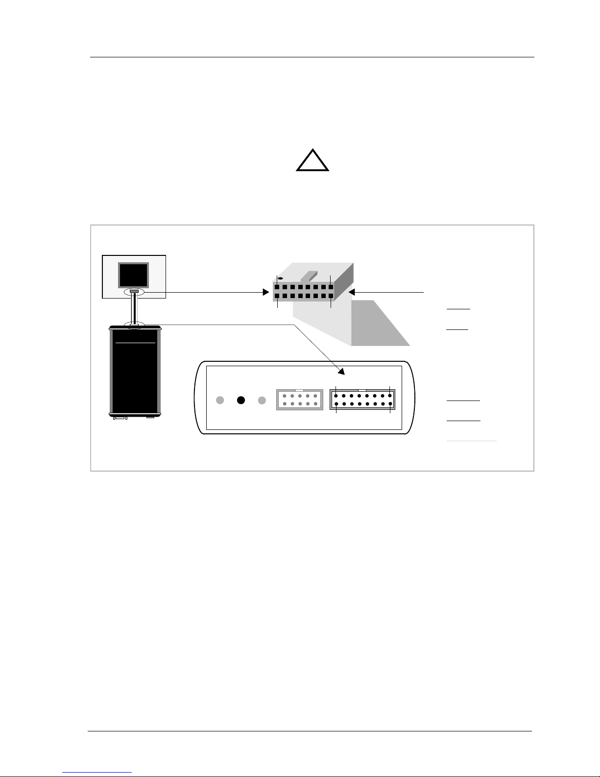
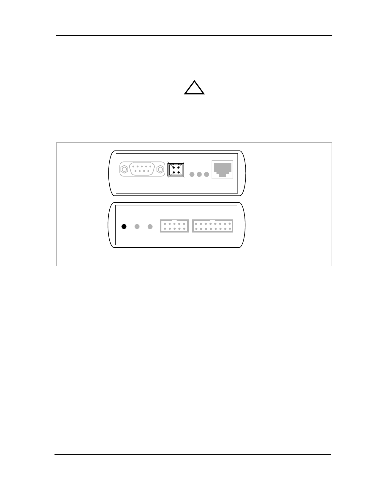
2.1 Connecting the BDI2000 to Target.........................................................................................4
2.1.1 Changing Target Processor Type .................................................................................6
2.2 Connecting the BDI2000 to Power Supply.............................................................................7
2.3 Status LED «MODE».............................................................................................................8
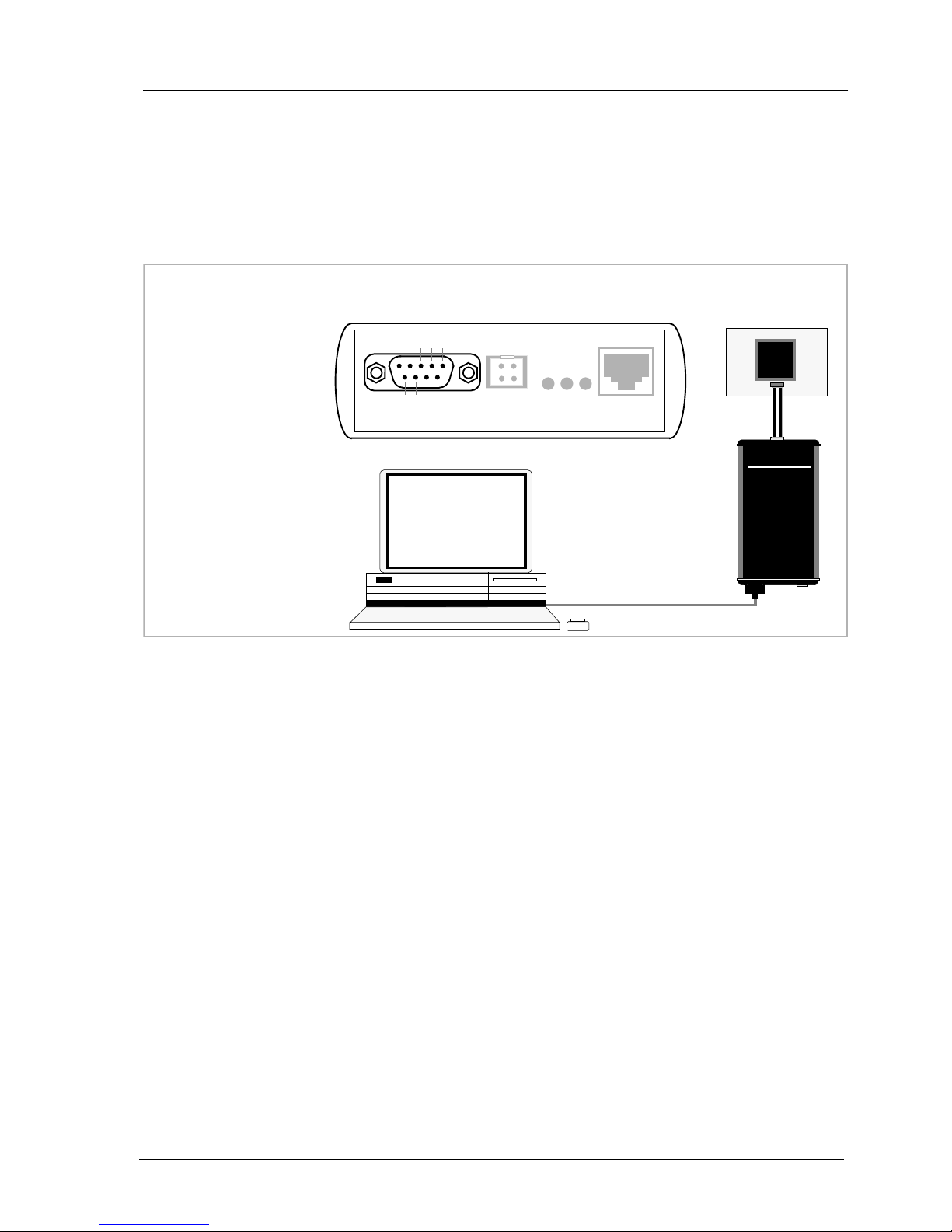
2.4 Connecting the BDI2000 to the Host.....................................................................................9
2.4.1 Serial line communication............................................................................................9
2.4.2 Ethernet communication ............................................................................................10
2.5 Installation of the Configuration Software............................................................................11
2.6 Configuration .......................................................................................................................12
2.6.1 BDI2000 Setup/Update..............................................................................................12
3 Init List........................................................................................................................................14
4 BDI working modes...................................................................................................................16
4.1 Startup Mode.......................................................................................................................17
4.1.1 Startup mode RESET ................................................................................................17
4.1.2 Startup Mode STOP...................................................................................................17
4.1.3 Startup mode RUN.....................................................................................................17
5 Working with EDGE Debugger .................................................................................................18
5.1 Direct Commands................................................................................................................18
5.1.1 Flash.Setup................................................................................................................19
5.1.2 Flash.Erase................................................................................................................19
5.1.3 Flash.Load .................................................................................................................19
5.1.4 Flash.Idle....................................................................................................................19
5.2 Download to Flash Memory.................................................................................................20
6 Telnet Interface ..........................................................................................................................23
7 Specifications............................................................................................................................24
8 Environmental notice................................................................................................................25
9 Declaration of Conformity (CE)................................................................................................25
10 Warranty...................................................................................................................................26
Appendices
A Troubleshooting........................................................................................................................27
B Maintenance..............................................................................................................................28
C Trademarks................................................................................................................................30

bdi
NDI
JTAG debug interface for EDGE Debugger, BDI2000 (PPC6xx/7xx/82xx/83xx)
User Manual 3
© Copyright 1992-2007 by ABATRON AG V 1.01
1 Introduction
The BDI2000 adds JTAG based debug features to the EDGE debugger environment from Mentor
Graphic’s. With the BDI2000, you control and monitor the microcontroller solely through the stable
on-chip debugging services.You won’t waste time and target resources with a software ROM monitor,
and you eliminate the cabling problems typical of ICE’s.This combination runs even when the target
system crashes and allows developers to continue investigating the cause of the crash.
A RS232 interface with a maximum of 115 kBaud and a 10Base-T Ethernet interface is available for
the host interface. The configuration software is used to update the firmware and to configure the
BDI2000 so it works with the EDGE debugger.
1.1 BDI2000
The BDI2000 is a processor system in a small box. It implements the interface between the JTAG
pins of the target CPU and a 10Base-T Ethernet / RS232 connector.The firmware and the program-
mable logic of the BDI2000 can be updated by the user with a simple Windows based configuration
program.The BDI2000 supports 1.8 – 5.0 Volts target systems (3.0 – 5.0 Volts target systems with
Rev. B).
PC Host
EDGE
Debugger
BDI2000
AA
AAbb
bbaa
aattttrr
rroo
oonn
nn AA
AAGG
GG SS
SSww
wwiiiiss
ssss
ss MM
MMaa
aadd
ddeeee
Target System
JTAG Interface
Ethernet (10 BASE-T)
PPC
750
BDI2000
AA
AAbb
bbaa
aattttrr
rroo
oonn
nn AA
AAGG
GG SS
SSww
wwiiiiss
ssss
ss MM
MMaa
aadd
ddeeee
Target System
JTAG Interface
MPC
8260
RS232

bdi
NDI
JTAG debug interface for EDGE Debugger, BDI2000 (PPC6xx/7xx/82xx/83xx)
User Manual 4
© Copyright 1992-2007 by ABATRON AG V 1.01
2 Installation
2.1 Connecting the BDI2000 toTarget
The cable to the target system is a 16 pin flat ribbon cable. In case where the target system has an
appropriate connector, the cable can be directly connected.The pin assignment is in accordance with
the PowerPC COP connector specification.
In order to ensure reliable operation of the BDI (EMC, runtimes, etc.) the target cable length must not
exceed 20 cm (8").
For BDI TARGET B connector signals see table on next page.
!
COP/JTAG Connector
BDI2000
AA
AAbb
bbaa
aattttrr
rroo
oonn
nn AA
AAGG
GG SS
SSww
wwiiiiss
ssss
ss MM
MMaa
aadd
ddeeee
Target System
PPC750 1 15
16
2
The green LED «TRGT» marked light up when target is powered up
BDI TRGT MODE TARGET A TARGET B
15 1
16 2
1 - TDO
2 - QACK
3 - TDI
4 - TRST
5 - HALTED
6 - Vcc Target
7 - TCK
8 - NC (RXD)
9 - TMS
10 - NC (TXD)
11 - SRESET
12 - GROUND
13 - HRESET
14 - NC (key)
15 - CKSTP_OUT
16 - GROUND

bdi
NDI
JTAG debug interface for EDGE Debugger, BDI2000 (PPC6xx/7xx/82xx/83xx)
User Manual 5
© Copyright 1992-2007 by ABATRON AG V 1.01
BDITARGET B Connector Signals:
Pin Name Describtion
1 TDO
JTAGTest Data Out
This input to the BDI2000 connects to the target TDO pin.
2QA
CK
QACK
Thisoutput oftheBDI2000 connectstothe targetQACKpin.By default this pinis not driven
by the BDI2000.With an entry in the init liste it can be forced low.
3 TDI
JTAGTest Data In
This output of the BDI2000 connects to the target TDI pin.
4 TRST
JTAGTest Reset
This output of the BDI2000 resets the JTAGTAP controller on the target.
5 IN0
General purpose Input
This input to the BDI2000 connects to the target HALTED pin. Currently not used.
6 Vcc Target
1.8 – 5.0V:
This is the target reference voltage.It indicates that the target has power and it is also used
to create the logic-level reference for the input comparators.It also controls the output logic
levels to the target.It is normally fed from Vdd I/O on the target board.
3.0 – 5.0V with Rev. B :
This input to the BDI2000 is used to detect if the target is powered up.If there is a current
limiting resistor between this pin and the target Vdd, it should be 100 Ohm or less.
7 TCK
JTAGTest Clock
This output of the BDI2000 connects to the target TCK pin.
8 <reseved>
9 TMS
JTAGTest Mode Select
This output of the BDI2000 connects to the target TMS line.
10 <reseved>
11 SRESET
Soft-Reset
This open collector output of the BDI2000 connects to the target SRESET pin.
12 GROUND
System Ground
13 HRESET
Hard-Reset
This open collector output of the BDI2000 connects to the target HRESET pin.
14 <reseved>
15 IN1
General purpose Input
This input to the BDI2000 connects to the target CKSTP_OUT pin. Currently not used.
16 GROUND
System Ground

bdi
NDI
JTAG debug interface for EDGE Debugger, BDI2000 (PPC6xx/7xx/82xx/83xx)
User Manual 6
© Copyright 1992-2007 by ABATRON AG V 1.01
2.1.1 ChangingTarget ProcessorType
Before you can use the BDI2000 with an other target processor type (e.g.CPU32 <--> PPC), a new
setup has to be done (see Appendix A). During this process the target cable must be disconnected
from the target system.The BDI2000 needs to be supplied with 5 Volts via the BDI OPTION connec-
tor (Version A) or via the POWER connector (Version B). For more information see chapter 2.2.1
«External Power Supply».
To avoid data line conflicts, the BDI2000 must be disconnected from the target system while
programming the logic for an other target CPU.
!

bdi
NDI
JTAG debug interface for EDGE Debugger, BDI2000 (PPC6xx/7xx/82xx/83xx)
User Manual 7
© Copyright 1992-2007 by ABATRON AG V 1.01
2.2 Connecting the BDI2000 to Power Supply
The BDI2000 needs to be supplied with 5 Volts (max. 1A) via the POWER connector.The available
power supply from Abatron (option) or the enclosed power cable can be directly connected.In order
to ensure reliable operation of the BDI2000, keep the power supply cable as short as possible.
For error-free operation, the power supply to the BDI2000 must be between 4.75V and 5.25V DC.
The maximal tolerable supply voltage is 5.25 VDC. Any higher voltage or a wrong polarity
might destroy the electronics.
Please switch on the system in the following sequence:
• 1 --> external power supply
• 2 --> target system
!
BDI TRGT MODE TARGET A TARGET B
POWER
1 - Vcc (+5V)
2 - VccTGT
3 - GROUND
4 - NOT USED
Connector
The green LED «BDI» marked light up when 5V power is connected to the BDI2000
RS232 POWER LI TX RX 10 BASE-T
1 Vcc
2
GND 3
4
Rev. B Version

bdi
NDI
JTAG debug interface for EDGE Debugger, BDI2000 (PPC6xx/7xx/82xx/83xx)
User Manual 8
© Copyright 1992-2007 by ABATRON AG V 1.01
2.3 Status LED «MODE»
The built in LED indicates the following BDI states:
MODE LED BDI STATES
OFF The BDI is ready for use, the firmware is already loaded.
ON The power supply for the BDI2000 is < 4.75VDC.
BLINK The BDI «loader mode» is active (an invalid firmware is loaded or loading firmware is active).
BDI TRGT MODE TARGET A TARGET B

bdi
NDI
JTAG debug interface for EDGE Debugger, BDI2000 (PPC6xx/7xx/82xx/83xx)
User Manual 9
© Copyright 1992-2007 by ABATRON AG V 1.01
2.4 Connecting the BDI2000 to the Host
2.4.1 Serial line communication
The host is connected to the BDI through the serial interface (COM1...COM4).The communication
cable between BDI and Host is a serial cable (RXD / TXD are crossed).There is the same connector
pinout for the BDI and for the Host side (Refer to Figure below).
RS232 Connector
(for PC host)
BDI2000
AA
AAbb
bbaa
aattttrr
rroo
oonn
nn AA
AAGG
GG SS
SSww
wwiiiiss
ssss
ss MM
MMaa
aadd
ddeeee
Target System
RS232
PC Host
1 - NC
2 - RXD data from host
3 - TXD data to host
4 - NC
5 - GROUND
6 - NC
7 - NC
8 - NC
9 - NC
RS232 POWER LI TX RX 10 BASE-T
54321
9876
MPC
8260

bdi
NDI
JTAG debug interface for EDGE Debugger, BDI2000 (PPC6xx/7xx/82xx/83xx)
User Manual 10
© Copyright 1992-2007 by ABATRON AG V 1.01
2.4.2 Ethernet communication
The BDI2000 has a built-in 10 BASE-T Ethernet interface (see figure below). Connect an UTP (Un-
shilded Twisted Pair) cable to the BD2000. For thin Ethernet coaxial networks you can connect a
commercially available media converter (BNC-->10 BASE-T) between your network and the
BDI2000. Contact your network administrator if you have questions about the network.
The following explains the meanings of the built-in LED lights:
LED Name Description
LI Link When this LED light is ON, data link is successful between the UTP
port of the BDI2000 and the hub to which it is connected.
TX Transmit WhenthisLEDlightBLINKS,dataisbeingtransmittedthrough the UTP
port of the BDI2000
RX Receive When this LED light BLINKS, data is being received through the UTP
port of the BDI2000
10 BASE-T
PC Host
Target System
Ethernet (10 BASE-T)
1 - TD+
2 - TD-
3 - RD+
4 - NC
5 - NC
6 - RD-
7 - NC
8 - NC
Connector
BDI2000
AA
AAbb
bbaa
aattttrr
rroo
oonn
nn AA
AAGG
GG SS
SSww
wwiiiiss
ssss
ss MM
MMaa
aadd
ddeeee
RS232 POWER LI TX RX 10 BASE-T
18 PPC

bdi
NDI
JTAG debug interface for EDGE Debugger, BDI2000 (PPC6xx/7xx/82xx/83xx)
User Manual 11
© Copyright 1992-2007 by ABATRON AG V 1.01
2.5 Installation of the Configuration Software
On the enclosed diskette you will find the BDI configuration software and the firmware required for
the BDI. Copy all these files to a directory on your hard disk.
The following files are on the diskette:
b20cop.exe Configuration program
b20cop.hlp Helpfile for the configuration program
b20cop.cnt Help contents file
b20copfw.xxx Firmware for BDI2000 for COP targets (PPC6xx/7xx/82xx)
copjed20.xxx JEDEC file for the BDI2000 (Rev. B) logic device programming
copjed21.xxx JEDEC file for the BDI2000 (Rev. C) logic device programming
bdiifc32.dll BDI Interface DLL for the configuration program
*.bdi Configuration Examples
Example of an installation process:
• Copy the entire contents of the enclosed diskette into a directory on the hard disk.
•You may create a new shortcut to the b20cop.exe configuration program.

bdi
NDI
JTAG debug interface for EDGE Debugger, BDI2000 (PPC6xx/7xx/82xx/83xx)
User Manual 12
© Copyright 1992-2007 by ABATRON AG V 1.01
2.6 Configuration
Before you can use the BDI together with the debugger, the BDI must be configured.Use the
SETUP
menu and follow the steps listed below:
• Load or update the firmware / logic, store IP address -->
Firmware
• Set the communication parameters between Host and BDI -->
Communication
• Setup an initialization list for the target processor -->
Initlist
• Select the working mode -->
Mode
• Transmit the configuration to the BDI -->
Mode Transmit
For information about the dialogs and menus use the help system (F1).
2.6.1 BDI2000 Setup/Update
First make sure that the BDI is properly connected (see Chapter 2.1 to 2.4).The BDI must be con-
nected via RS232 to the Windows host.
To avoid data line conflicts, the BDI2000 must be disconnected from the target system while
programming the logic for an other target CPU (see Chapter 2.1.1).
The following dialogbox is used to check or update the BDI firmware and logic and to set the network
parameters.
dialog box «BDI2000 Update/Setup»
The following options allow you to check or update the BDI firmware and logic and to set the network
parameters:
Channel Select the communication port where the BDI2000 is connected during
this setup session.
Baudrate Select the baudrate used to communicate with the BDI2000 loader during
this setup session.
!

bdi
NDI
JTAG debug interface for EDGE Debugger, BDI2000 (PPC6xx/7xx/82xx/83xx)
User Manual 13
© Copyright 1992-2007 by ABATRON AG V 1.01
Connect Click on this button to establish a connection with the BDI2000 loader.
Once connected, the BDI2000 remains in loader mode until it is restarted
or this dialog box is closed.
Current Press this button to read back the current loaded BDI2000 software and
logic versions. The current loader, firmware and logic version will be dis-
played.
Update This button is only active if there is a newer firmware or logic version
present in the execution directory of the BDI setup software. Press this
button to write the new firmware and/or logic into the BDI2000 flash mem-
ory / programmable logic.
IP Address Enter the IP address for the BDI2000.
Use the following format: xxx.xxx.xxx.xxxe.g.151.120.25.101
Ask your network administrator for assigning an IP address to this
BDI2000. Every BDI2000 in your network needs a different IP address.
Subnet Mask Enter the subnet mask of the network where the BDI is connected to.
Use the following format: xxx.xxx.xxx.xxxe.g.255.255.255.0
A subnet mask of 255.255.255.255 disables the gateway feature.
Ask your network administrator for the correct subnet mask.
Default Gateway Enter the IP address of the default gateway.Ask your network administra-
tor for the correct gateway IP address. If the gateway feature is disabled,
you may enter 255.255.255.255 or any other value..
Transmit Click on this button to store the network configuration in the BDI2000 flash
memory.
In rare instances you may not be able to load the firmware in spite of a correctly connected BDI (error
of the previous firmware in the flash memory).Before carrying out the following procedure,check
the possibilities in Appendix «Troubleshooting». In case you do not have any success with the
tips there, do the following:
• Switch OFF the power supply for the BDI and open the unit as
described in Appendix «Maintenance»
• Place the jumper in the «INIT MODE» position
• Connect the power cable or target cable if the BDI is powered
from target system
• Switch ON the power supply for the BDI again and wait until the
LED «MODE» blinks fast
• Turn the power supply OFF again
• Return the jumper to the «DEFAULT» position
• Reassemble the unit as described in Appendix «Maintenance»
INIT MODE
DEFAULT

bdi
NDI
JTAG debug interface for EDGE Debugger, BDI2000 (PPC6xx/7xx/82xx/83xx)
User Manual 14
© Copyright 1992-2007 by ABATRON AG V 1.01
3 Init List
dialog box «Startup Init List»
In order to prepare the target for debugging, you can define an Initialization List.This list is stored in
the Flash memory of the BDI2000 and worked through every time the target comes out of reset.Use
it to get the target operational after a reset.The memory system is usually initialized through this list.
After processing the init list, the RAM used to download the application must be accessible.
Use on-line help (F1) and the supplied configuration examples on the distribution disk to get more
information about the init list.
Special BDI Configuration Registers:
In order to change some special configuration parameters of the BDI, the SPR entry in the init list is
used. Normal PPC SPR's covers a range from 0 to 1023. Other SPR's are used to set BDI internal
registers:
8001 For slow memory it may be necessary to increase the number of clocks used to execute a
memory access cycle. If for example you cannot access boot ROM content with the default
configuration of your memory controller, define additional memory access clocks with this
SPR number in the init list.Usual values are in the range 1000 - 4000 (0x400 - 0x1000).
8002 Defines an alternate boot address. Normally a PPC boots from 0xFFF00100. A MPC8260
has also the option to boot from 0x00000100.The BDI needs to know the boot address in
order to set the correct hardware breakpoint during startup..
8003 Defines the base address of the L2 cache private memory.Because L2 cache private mem-
ory cannot be accessed directly via JTAG, the BDI loads some support code into the work-
space and uses it to access this memory range. Therefore a workspace is necessary to
access this memory range.
8004 Defines the size of the L2 cache private memory in bytes (e.g. 0x100000 for 1Mbyte).

bdi
NDI
JTAG debug interface for EDGE Debugger, BDI2000 (PPC6xx/7xx/82xx/83xx)
User Manual 15
© Copyright 1992-2007 by ABATRON AG V 1.01
8006 Write to this special register with a value of 1, if the BDI should use the alternate single step
mode.The alternate mode does not use the trace bit (MSR[SE]) to implement single step-
ping. It uses always a hardware breakpoint (via IABR) on the next instruction to implement
single stepping.
8007 Write to this special register with a value of 1, if the PPC core operates in 32-bit data bus
mode.
8008 If the BDI should generate data parity bits when writing to memory, write to this special reg-
ister with a value of 1.
8009 This entry in the init list allows to define a delay time (in ms) the BDI inserts between releas-
ing the COP-HRESET line and starting communicating with the target.This init list entry may
be necessary if COP-HRESET is delayed on its way to the PowerPC reset pin.
8010 If the BDI should forces the QACK pin (pin 2) on the COP connector low, write to this special
register a value of 1. By default the QACK pin is not driven by the BDI.This option maybe
useful for PPC750 and PPC7400 targets.
The MPC83xx processors allows to override the Reset ConfigurationWord (RCW) via JTAG.The fol-
lowing two special configuration parameters define the RCW. Always define both words.
8020 Reset Configuration Word High (RCWH).
8021 Reset Configuration Word Low (RCWL).
For MPC83xx processors the BDI supports True Little Endian (TLE) mode. Have also a look at the
TLE configuration example ( mpc8349e_le.bdi ).
8022 Write to this special register with a value of 1 to select True Little Endian mode.
The BDI can also handle systems with multiple devices connected to the JTAG scan chain. In order
to put the other devices into BYPASS mode and to count for the additional bypass registers, the BDI
needs some information about the scan chain layout. Enter the number and total instruction register
(IR) length of the devices present before the PowerPC chip. Enter the appropriate information also
for the devices following the PowerPC chip.
8011 Number of JTAG devices connected before the PowerPC chip.
8012 Total IR length of the JTAG devices connected before the PowerPC chip
8013 Number of JTAG devices connected after the PowerPC chip
8014 Total IR length of the JTAG devices connected after the PowerPC chip

bdi
NDI
JTAG debug interface for EDGE Debugger, BDI2000 (PPC6xx/7xx/82xx/83xx)
User Manual 16
© Copyright 1992-2007 by ABATRON AG V 1.01
4 BDI working modes
dialog box «BDI Working Mode»
With this dialog box you can define how the BDI interacts with the target system.
Identification Enter a text to identify this setup.
Startup Startup mode defines how the BDI interacts with the target processor after
reset or power up.The options RESET, STOP or RUN can be selected.
CPU Type Select the CPU type of the target system.
JTAG Clock This option allows to select the used JTAG clock rate.
Run Time When startup mode STOP is selected, this option allows to set the run
time after reset in milliseconds until the target CPU is stopped. Values
from 100 (0.1 sec) till 32000 (32 sec) are accepted.
Workspace In order to speed up code download, enter the address of a free 256 byte
RAM area.The BDI will install there some code that supports faster pro-
gram download.A value of 0xFFFFFFFF disables the workspace.The BDI
also needs this workspace to flush the data cache and to access L2 pri-
vate memory.
Catch exceptions Check this switch if the BDI should catch unhandled exception. Catching
exceptions is only possible if the memory at address 0x00000100 to
0x00001FFF is writable and the vector table is mapped to 0x00000000
(MSR[IP] = 0).
Flush L2/L3 cache Check this switch if the BDI should flush the cache before accessing mem-
ory.This is mainly useful if there is a L2/L3 cache present.If this switch is
not set, the BDI uses L1 cache coherent read and write accesses to target
memory.Coherent access means, that the cache is directly read or written
via COP if the appropriate cache line is valid. In order to flush the data
cache, the BDI needs some workspace in target RAM to execute the flush
code.Do not check this switch if there is only a L1 cache present.
Transmit Click on this button to send the initialization list and the working mode to
the BDI. This is normally the last step done before the BDI can be used
with the debugging system.

bdi
NDI
JTAG debug interface for EDGE Debugger, BDI2000 (PPC6xx/7xx/82xx/83xx)
User Manual 17
© Copyright 1992-2007 by ABATRON AG V 1.01
4.1 Startup Mode
Startup mode defines how the BDI interacts with the target system after a reset or power up
sequence.
4.1.1 Startup mode RESET
In this mode no ROM is required on the target system.The necessary initialization is done by the BDI
with the programmed init list.The following steps are executed by the BDI after system reset or
system power up:
• HRESET is activated on the target system.
• HRESET is deactivated and the target is forced into debug mode.
• The BDI works through the initialization list.
The RESET mode is the standard working mode. Other modes are used in special cases (i.e.
applications in ROM, special requirements on the reset sequence...).
4.1.2 Startup Mode STOP
In this mode the initialization code is in a ROM on the target system.The code in this ROM handles
base initialization. At the end of the code, the initialization program enters an endless loop until it is
interrupted by the BDI.This mode is intended for special requirements on the reset sequence (e.g.
loading a RAM based programmable logic device).
In this mode the following steps are executed by the BDI after system reset or power up:
• HRESET is activated on the target system.
• HRESET is deactivated and the target begins executing application code.
• After a delay (Run Time), the target is forced into debug mode.
• The BDI works through the initialization list.
4.1.3 Startup mode RUN
This mode is used to debug an application which is already stored in ROM.The application is started
normally and will be stopped when the debugger is started.
In this mode, the following steps are executed by the BDI after system reset or power up:
• HRESET is activated on the target system.
• HRESET is deactivated and the target begins executing application code.
• The application runs until it is stopped by the debugger.

bdi
NDI
JTAG debug interface for EDGE Debugger, BDI2000 (PPC6xx/7xx/82xx/83xx)
User Manual 18
© Copyright 1992-2007 by ABATRON AG V 1.01
5Working with EDGE Debugger
For information about using the EDGE debugger look at the appropriate EDGE user’s manual.
5.1 Direct Commands
For special functions (mainly for flash programming) the BDI supports so called «Direct Commands».
This commands can be entered in a codelet file (e.g. PRELOAD.CDL) or directly executed in the
EDGE Debugger Command Line Window.This Direct Commands are not interpreted by the EDGE
Debugger but directly sent to the BDI. After processing the command the result is displayed in the
EDGE Debugger Command Line Window.
Direct Commands are ASCII - Strings with the following structure:
<Object>.<Action> [<ParName>=<ParValue>]...
Example: flash.erase addr=0x02800000
All names are case insensitive. Parameter values are numbers or strings. Numeric parameters can
be entered as decimal (e.g.700) or as hexadecimal (0x80000) values.
If the commands are directly entered in the EDGE Debugger Command LineWindow, use the follow-
ing syntax:
bdi "direct-command"
Example: bdi "flash.erase addr=0x02800000"

bdi
NDI
JTAG debug interface for EDGE Debugger, BDI2000 (PPC6xx/7xx/82xx/83xx)
User Manual 19
© Copyright 1992-2007 by ABATRON AG V 1.01
5.1.1 Flash.Setup
In order to support loading into flash memory, the BDI needs some information about the used flash
devices.Before any other flash related command can be used, this direct command must be execut-
ed.
Syntax: flash.setup type=am29f size=0x80000 bus=32 workspace=0x1000
type This parameter defines the type of flash used.It is used to select the correct program-
ming algorithm.The following flash types are supported:
AM29F, AM29BX8, AM29BX16, I28BX8, I28BX16, AT49, AT49X8, AT49X16,
STRATAX8, STRATAX16, MIRROR, MORRORX8, MIRRORX16,
I28BX32, AM29DX16, AM29DX32
size The size of one flash chip in bytes (e.g. AM29F010 = 0x20000).This value is used to
calculate the starting address of the current flash memory bank.
bus The width of the memory bus that leads to the flash chips. Do not enter the width of
the flash chip itself.The parameter TYPE carries the information about the number of
data lines connected to one flash chip. For example, enter 16 if you are using two
AM29F010 to build a 16bit flash memory bank.
workspace If a workspace is defined, the BDI uses a faster programming algorithm that run out of
RAM on the target system. Otherwise, the algorithm is processed within the BDI.The
workspace is used for a 1kByte data buffer and to store the algorithm code.There must
be at least 2kBytes of RAM available for this purpose.
5.1.2 Flash.Erase
This command allows to erase one flash sector, block or chip.
Syntax: flash.erase addr=0x02800000 mode=chip
addr The start address of the flash sector to erase.
mode This parameter defines the erase mode.The following modes are supported:
CHIP, BLOCK and SECTOR (default is sector erase)
5.1.3 Flash.Load
This command enables loading to flash memory. If the address of a data block is within the given
flash range, the BDI automatically uses the appropriate programming algorithm.This command must
be executed before downloading is started.
Syntax: flash.load addr=0x02800000 size=0x200000
addr The start address of the flash memory
size The size of the flash memory
5.1.4 Flash.Idle
This command disables loading to flash memory.
Syntax: flash.idle

bdi
NDI
JTAG debug interface for EDGE Debugger, BDI2000 (PPC6xx/7xx/82xx/83xx)
User Manual 20
© Copyright 1992-2007 by ABATRON AG V 1.01
5.2 Download to Flash Memory
The BDI supports programming flash memory. To automate the process of downloading to flash
memory a codelet can be used.Following an example of such a codelet:
void flash_load(int coreId)
{
char output[256];
printf("Specifying the flash type...");
command("bdi flash.setup type=AM29F size=0x00800000 bus=8",output, 256);
printf("%s\n", output);
printf("Erasing the first sector...");
command("bdi flash.erase addr=0xfff00000 mode=sector", output,256);
printf("%s\n", output);
printf("Erasing the second sector...");
command("bdi flash.erase addr=0xfff10000 mode=sector", output,256);
printf("%s\n", output);
printf("Erasing the third sector...");
command("bdi flash.erase addr=0xfff20000 mode=sector", output,256);
printf("%s\n", output);
printf("Setting load address...");
command("bdi flash.load addr=0xfff00000 size=0x00020000",output, 256);
printf("%s\n", output);
printf("Loading the image...");
command("load C:\\MGC\\embedded\\Nucleus\\demo\\out\\plus_demo.out", output, 256);
printf("%s\n", output);
printf("Taking the BDI out of Flashing mode...");
command("bdi flash.idle", output, 256);
printf("%s\n", output);
}
A user who needs to reflash often can just call such a codelet from the EDGE Debugger command
view by typing flash_load(1) at the command prompt. For this to work two steps are required:
1.The codelet file must first be loaded into EGDE.
• From the Run Menu select "Codelet Composer"
• On the Codelet Composer dialog click the Load button.
• Browse to and select your *.cdl file.
• To complete the operation click the Open button.
Alternatively, any *.cdl file that is simply imported into one of the user's projects will be identified by
EDGE Debugger.
2. Since the flashing commands are issued over the debug connection, this of course requires that
a connection to already been established to the target.
In addition, the contents of the codelet can be placed in the user's initialization codelet and thus be
called automatically after connect.
Other manuals for BDI2000
10
Table of contents
Other Abatron Computer Accessories manuals