Abatron BDI2000 User manual

bdi
Access
JTAG interface library
MIPS32
Installation Manual
Manual Version 1.00 for BDI2000
© 1992-2004 ABATRON AG

bdi
Access
JTAG interface library, BDI2000 (MIPS32) Installation Manual 2
© Copyright 1992-2004 by ABATRON AG V 1.00
1 Introduction .................................................................................................................................3
1.1 BDI2000.................................................................................................................................3
2 Installation ...................................................................................................................................4
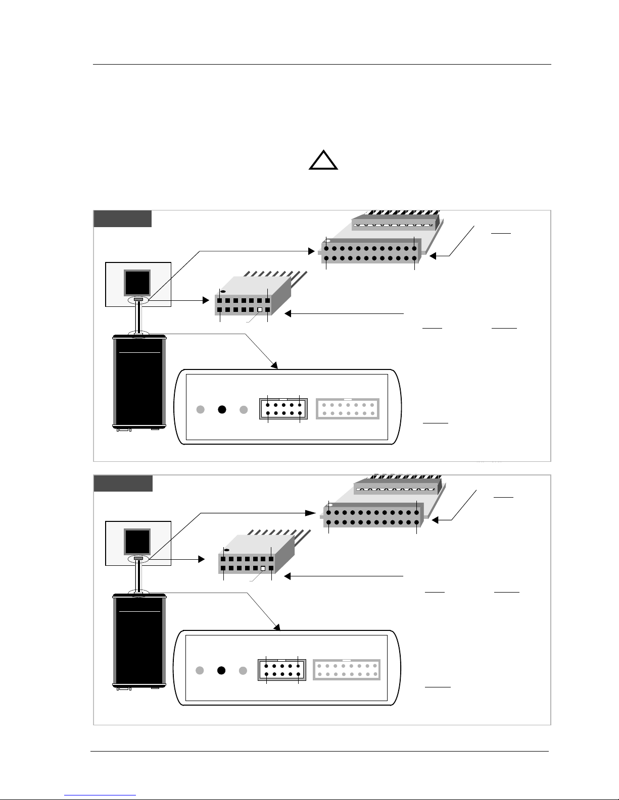
2.1 Connecting the BDI2000 to Target.........................................................................................4
2.1.1 Changing Target Processor Type .................................................................................6
2.2 Connecting the BDI2000 to Power Supply.............................................................................7
2.2.1 External Power Supply.................................................................................................7
2.2.2 Power Supply from Target System...............................................................................8
2.3 Status LED «MODE».............................................................................................................9
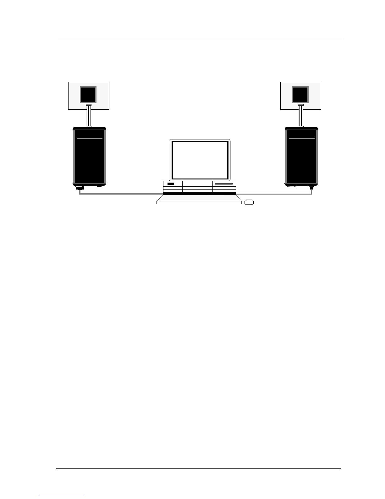
2.4 Connecting the BDI2000 to Host.........................................................................................10
2.4.1 Serial line communication..........................................................................................10
2.4.2 Ethernet communication ............................................................................................11
2.5 Installation of the Configuration Software............................................................................12
2.6 BDI2000 Setup/Update........................................................................................................13
2.6.1 Linux/Unix Hosts........................................................................................................13
2.6.2 Windows Hosts...........................................................................................................14
2.6.3 Recover procedure.....................................................................................................15
3 Specifications............................................................................................................................16
4 Environmental notice................................................................................................................17
5 Declaration of Conformity (CE)................................................................................................17
6 Warranty.....................................................................................................................................18
Appendices
A Troubleshooting........................................................................................................................19
B Maintenance..............................................................................................................................20
C Trademarks................................................................................................................................22

bdi
Access
JTAG interface library, BDI2000 (MIPS32) Installation Manual 3
© Copyright 1992-2004 by ABATRON AG V 1.00
1 Introduction
The bdiAccess library can be used to access the BDI2000 functions.With this library, a program run-
ning on a Windows/Linux/Unix host can take advantage of the JTAG interface of an MIPS32 based
target processor and execute the following tasks:
• Read/Write target registers
• Read/Write target memory
• Reset/Startup target
• Flash programming
• Start/Stop program execution
This Installation Manual shows how to connect the BDI2000 to a MIPS32 based target and how to
install the bdiAccess software. The interface to the library is defined in a different document that is
target independent.
1.1 BDI2000
The BDI2000 is a processor system in a small box. It implements the interface between the JTAG
pins of the target CPU and a 10Base-T Ethernet / RS232 connector.The firmware and the program-
mable logic of the BDI2000 can be updated by the user with a simple Windows based configuration
program.The BDI2000 supports 1.8 – 5.0 Volts target systems (3.0 – 5.0 Volts target systems with
Rev. A/B).
Host
BDI2000
AA
AAbb
bbaa
aattttrr
rroo
oonn
nn AA
AAGG
GG SS
SSww
wwiiiiss
ssss
ss MM
MMaa
aadd
ddeeee
Target System
JTAG Interface
Ethernet (10 BASE-T)
BDI2000
AA
AAbb
bbaa
aattttrr
rroo
oonn
nn AA
AAGG
GG SS
SSww
wwiiiiss
ssss
ss MM
MMaa
aadd
ddeeee
Target System
JTAG Interface
MIPS
RS232
MIPS

bdi
Access
JTAG interface library, BDI2000 (MIPS32) Installation Manual 4
© Copyright 1992-2004 by ABATRON AG V 1.00
2 Installation
2.1 Connecting the BDI2000 toTarget
The cables to the target system are designed for the IDT RC32300 Development Boards (optional
available: Part# 90070) and for EJTAG 2.5 compatible boards (enclosed). In case where the target
system has the same connector layout, the cable (14 pin or 24 pin) can be directly connected.
In order to ensure reliable operation of the BDI (EMC, runtimes, etc.) the target cable length must not
exceed 25 cm (10").
For BDI MAIN / TARGET A connector signals see table on next page.
!
BDI TRGT MODE BDI MAIN BDI OPTION
14 pin EJTAG
BDI2000
AA
AAbb
bbaa
aattttrr
rroo
oonn
nn AA
AAGG
GG SS
SSww
wwiiiiss
ssss
ss MM
MMaa
aadd
ddeeee
Target System
MIPS
9
1 13
14
2
1
10 2
The green LED «TRGT» marked light up when target is powered up
Rev. A
1
24
2
Connector
1 - TRST
2 - GROUND
3 - TDI
4 - GROUND
5 - TDO
6 - GROUND
7 - TMS
8 - GROUND
9 - TCK
10 - GROUND
11 - RESET
12 - GROUND
13 - NC
14 - GROUND
15 - NC
16 - GROUND
17 - NC
18 - GROUND
19 - NC
20 - GROUND
21 - DBGBOOT
22 - GROUND
23 - VIO Target
24 - GROUND
20 NC
1 - TRST
2 - NC
3 - TDI
4 - NC
5 - TDO
6 - GROUND
7 - TMS
8 - GROUND
9 - TCK
10 - NC
11 - RESET
12 - key
13 - DINT
14 - VIO Target
24 pin RC32300
Connector
23
optional
available
(P/N 90070)
Key
BDI2000
AA
AAbb
bbaa
aattttrr
rroo
oonn
nn AA
AAGG
GG SS
SSww
wwiiiiss
ssss
ss MM
MMaa
aadd
ddeeee
Target System
MIPS 1 13
14
2
The green LED «TRGT» marked light up when target is powered up
BDI TRGT MODE TARGET A TARGET B
9 1
10 2
Rev. B/C
14 pin EJTAG
1
24
2
Connector
1 - TRST
2 - GROUND
3 - TDI
4 - GROUND
5 - TDO
6 - GROUND
7 - TMS
8 - GROUND
9 - TCK
10 - GROUND
11 - RESET
12 - GROUND
13 - NC
14 - GROUND
15 - NC
16 - GROUND
17 - NC
18 - GROUND
19 - NC
20 - GROUND
21 - DBGBOOT
22 - GROUND
23 - VIO Target
24 - GROUND
1 - TRST
2 - NC
3 - TDI
4 - NC
5 - TDO
6 - GROUND
7 - TMS
8 - GROUND
9 - TCK
10 - NC
11 - RESET
12 - key
13 - DINT
14 - VIO Target
24 pin RC32300
Connector
23
optional
available
(P/N 90070)
Key

bdi
Access
JTAG interface library, BDI2000 (MIPS32) Installation Manual 5
© Copyright 1992-2004 by ABATRON AG V 1.00
BDI MAIN /TARGET A Connector Signals
Pin Name Describtion
1 DINT
EJTAG Debug Interrupt
EJTAG 2.5:This output of the BDI2000 connects to the target DINT line.
RC32300:This output of the BDI2000 connects to the target DebugBoot line.
2 TRST
EJTAGTest Reset
This output of the BDI2000 resets the JTAGTAP controller on the target.
3+5 GND
System Ground
4 TCK
EJTAGTest Clock
This output of the BDI2000 connects to the target TCK line.
6 TMS
EJTAGTest Mode Select
This output of the BDI2000 connects to the target TMS line.
7 RESET This open collector output of the BDI2000 is used to reset the target system.
8 TDI
EJTAGTest Data In
This output of the BDI2000 connects to the target TDI line.
9 VIO Target
1.8 – 5.0V:
This is the target reference voltage.It indicates that the target has power and it is also used
to create the logic-level reference for the input comparators.It also controls the output logic
levels to the target.It is normally fed from Vdd I/O on the target board.
3.0 – 5.0V with Rev. A/B :
This input to the BDI2000 is used to detect if the target is powered up.If there is a current
limiting resistor between this pin and the target Vdd, it should be 100 Ohm or less.
10 TDO
EJTAGTest Data Out
This input to the BDI2000 connects to the target TDO line.

bdi
Access
JTAG interface library, BDI2000 (MIPS32) Installation Manual 6
© Copyright 1992-2004 by ABATRON AG V 1.00
2.1.1 ChangingTarget ProcessorType
Before you can use the BDI2000 with an other target processor type (e.g. ARM <--> MIPS), a new
setup has to be done (see chapter 2.5). During this process the target cable must be disconnected
from the target system.The BDI2000 needs to be supplied with 5 Volts via the BDI OPTION connec-
tor (Rev. A) or via the POWER connector (Rev. B/C). For more information see chapter 2.2.1
«External Power Supply»).
To avoid data line conflicts, the BDI2000 must be disconnected from the target system while
programming the logic for an other target CPU.
!

bdi
Access
JTAG interface library, BDI2000 (MIPS32) Installation Manual 7
© Copyright 1992-2004 by ABATRON AG V 1.00
2.2 Connecting the BDI2000 to Power Supply
2.2.1 External Power Supply
The BDI2000 needs to be supplied with 5 Volts (max. 1A) via the BDI OPTION connector (Rev. A)
or via POWER connector (Rev. B/C). The available power supply from Abatron (option) or the en-
closed power cable can be directly connected. In order to ensure reliable operation of the BDI2000,
keep the power supply cable as short as possible.
For error-free operation, the power supply to the BDI2000 must be between 4.75V and 5.25V DC.
The maximal tolerable supply voltage is 5.25 VDC. Any higher voltage or a wrong polarity
might destroy the electronics.
Please switch on the system in the following sequence:
• 1 --> external power supply
• 2 --> target system
!
BDI TRGT MODE BDI MAIN BDI OPTION
13
1
14 2
BDI OPTION
1 - NOT USED
2 - GROUND
3 - NOT USED
4 - GROUND
5 - NOT USED
6 - GROUND
7 - NOT USED
8 - GROUND
9 - NOT USED
10 - GROUND
11 - NOT USED
12 - Vcc (+5V)
13 - Vcc Target (+5V)
14 - Vcc (+5V)
Vcc GND
Connector
The green LED «BDI» marked light up when 5V power is connected to the BDI2000
Rev. A
BDI TRGT MODE TARGET A TARGET B
POWER
1 - Vcc (+5V)
2 - VccTGT
3 - GROUND
4 - NOT USED
Connector
The green LED «BDI» marked light up when 5V power is connected to the BDI2000
RS232 POWER LI TX RX 10 BASE-T
1 Vcc
2
GND 3
4
Rev. B Version
Rev. B/C

bdi
Access
JTAG interface library, BDI2000 (MIPS32) Installation Manual 8
© Copyright 1992-2004 by ABATRON AG V 1.00
2.2.2 Power Supply fromTarget System
The BDI2000 needs to be supplied with 5 Volts (max. 1A) via BDI MAIN target connector (Rev. A) or
via TARGET A connector (Rev. B/C).This mode can only be used when the target system runs with
5V and the pin «Vcc Target» is able to deliver a current up to 1A@5V. For pin description and layout
see chapter 2.1 «Connecting the BDI2000 toTarget».Insert the enclosed Jumper as shown in figure
below.
Please ensure that the jumper is inserted correctly
.
For error-free operation, the power supply to the BDI2000 must be between 4.75V and 5.25V DC.
The maximal tolerable supply voltage is 5.25 VDC. Any higher voltage or a wrong polarity
might destroy the electronics.
!
BDI TRGT MODE BDI MAIN BDI OPTION
13
1
14 2
BDI OPTION
Connector
The green LEDs «BDI» and «TRGT» marked light up when target is powered up
Jumper
and the jumper is inserted correctly
1 - NOT USED
2 - GROUND
3 - NOT USED
4 - GROUND
5 - NOT USED
6 - GROUND
7 - NOT USED
8 - GROUND
9 - NOT USED
10 - GROUND
11 - NOT USED
12 - Vcc (+5V)
13 - Vcc Target (+5V)
14 - Vcc BDI2000 (+5V)
Rev. A
BDI TRGT MODE TARGET A TARGET B
POWER
1 - Vcc BDI2000 (+5V)
2 - Vcc Target (+5V)
3 - GROUND
4 - NOT USED
Connector
RS232 POWER LI TX RX 10 BASE-T
1
2
3
4
The green LEDs «BDI» and «TRGT» marked light up when target is powered up
and the jumper is inserted correctly
Jumper
Rev. B/C

bdiAccess
JTAG interface library, BDI2000 (MIPS32) Installation Manual 9
© Copyright 1992-2004 by ABATRON AG V 1.00
2.3 Status LED «MODE»
The built in LED indicates the following BDI states:
MODE LED BDI STATES
OFF The BDI is ready for use, the firmware is already loaded.
ON The power supply for the BDI2000 is < 4.75VDC.
BLINK The BDI «loader mode» is active (an invalid firmware is loaded or loading firmware is active).
BDI TRGT MODE BDI MAIN BDI OPTION
BDI TRGT MODE TARGET A TARGET B
Rev. A
Rev. B/C

bdiAccess
JTAG interface library, BDI2000 (MIPS32) Installation Manual 10
© Copyright 1992-2004 by ABATRON AG V 1.00
2.4 Connecting the BDI2000 to Host
2.4.1 Serial line communication
The host is connected to the BDI through the serial interface (COM1...COM4).The communication
cable between BDI and Host is a serial cable (RXD /TXD are crossed).There is the same connector
pinout for the BDI and for the Host side (Refer to Figure below).
RS232 Connector
(for PC host)
BDI2000
AA
AAbb
bbaa
aattttrr
rroo
oonn
nn AA
AAGG
GG SS
SSww
wwiiiiss
ssss
ss MM
MMaa
aadd
ddeeee
Target System
RS232
RS232 LI TX RX 10 BASE-T
54321
9876
PC Host
1 - NC
2 - RXD data from host
3 - TXD data to host
4 - NC
5 - GROUND
6 - NC
7 - NC
8 - NC
9 - NC
Rev. A
MIPS
RS232 Connector
(for PC host)
BDI2000
AA
AAbb
bbaa
aattttrr
rroo
oonn
nn AA
AAGG
GG SS
SSww
wwiiiiss
ssss
ss MM
MMaa
aadd
ddeeee
Target System
RS232
PC Host
1 - NC
2 - RXD data from host
3 - TXD data to host
4 - NC
5 - GROUND
6 - NC
7 - NC
8 - NC
9 - NC
Rev. B/C
RS232 POWER LI TX RX 10 BASE-T
54321
9876
MIPS

bdiAccess
JTAG interface library, BDI2000 (MIPS32) Installation Manual 11
© Copyright 1992-2004 by ABATRON AG V 1.00
2.4.2 Ethernet communication
The BDI2000 has a built-in 10 BASE-T Ethernet interface (see figure below). Connect an UTP (Un-
shilded Twisted Pair) cable to the BD2000. For thin Ethernet coaxial networks you can connect a
commercially available media converter (BNC-->10 BASE-T) between your network and the
BDI2000. Contact your network administrator if you have questions about the network.
The following explains the meanings of the built-in LED lights:
LED Name Description
LI Link When this LED light is ON, data link is successful between the UTP
port of the BDI2000 and the hub to which it is connected.
TX Transmit WhenthisLEDlightBLINKS,dataisbeingtransmittedthrough the UTP
port of the BDI2000
RX Receive When this LED light BLINKS, data is being received through the UTP
port of the BDI2000
10 BASE-T
PC Host
Target System
Ethernet (10 BASE-T)
1 - TD+
2 - TD-
3 - RD+
4 - NC
5 - NC
6 - RD-
7 - NC
8 - NC
Connector
RS232 LI TX RX 10 BASE-T
BDI2000
AA
AAbb
bbaa
aattttrr
rroo
oonn
nn AA
AAGG
GG SS
SSww
wwiiiiss
ssss
ss MM
MMaa
aadd
ddeeee
18
RS232 POWER LI TX RX 10 BASE-T
Rev. A
Rev. B/C
18 MIPS

bdiAccess
JTAG interface library, BDI2000 (MIPS32) Installation Manual 12
© Copyright 1992-2004 by ABATRON AG V 1.00
2.5 Installation of the Configuration Software
On the enclosed diskette you will find the bdiAccess library, the BDI configuration software and the
firmware required for the BDI. Copy the appropriate files to a directory on your hard disk.
Windows and Linux/Unix hosts:
manual.pdf This installation manual in pdf format
bdiacc.pdf The bdiAccess interface specification in pdf format
b20r4kfw.xxx Firmware for BDI2000 for MIPS32 targets
r4kjed20.xxx JEDEC file for the BDI2000 (Rev. A/B) logic device programming
r4kjed21.xxx JEDEC file for the BDI2000 (Rev. C) logic device programming
Only for Windows hosts:
accr4k.exe Setup and demo program (WIN32 application)
accr4k.hlp Helpfile for the setup and demoprogram
bdiifc32.dll The bdiAccess library (WIN32-DLL)
bdiifc32.lib The import library for the bdiAccess DLL (WIN32)
bdiifc.h The C header file showing the interface to the bdiAccess DLL
access.txt Information file used by the demo program
access.ini Initialisation file for the demo program
Only for Linux/Unix hosts:
bdiaccux.zip Archive with the bdiAccess sources for Linux/Unix hosts
bdisetup.zip Archive with the BDI setup utility sources for Linux/Unix hosts

bdiAccess
JTAG interface library, BDI2000 (MIPS32) Installation Manual 13
© Copyright 1992-2004 by ABATRON AG V 1.00
2.6 BDI2000 Setup/Update
First make sure that the BDI is properly connected (see Chapter 2.1 to 2.4).The BDI must be con-
nected via RS232 to the Windows host.
To avoid data line conflicts, the BDI2000 must be disconnected from the target system while
programming the logic for an other target CPU (see Chapter 2.1.1).
2.6.1 Linux/Unix Hosts
In order to update the firmware / logic of the BDI and to set the network parameters, a setup tool is
included for Linux/Unix hosts. In the ZIP Archive bdisetup.zip are all sources to build this utility.
This command line utility can be used to update the firmware and logic of the BDI2000.It is also used
to transfer the network configuration.There are 4 tasks the utility can process:
• Reading the current loaded firmware / logic version
• Erasing the firmware and logic
• Updating the firmware and logic
• Storing the network configuration parameters into the BDI flash
Every of this task is started by executing the setup utility with different parameters.The first param-
eter always selects the task to execute:
bdisetup { -v | -e | -u | -c } [additional parameters]
-v Read version
-e Erase firmware and logic
-u Update firmware and/or logic
-c Store network configuration
There are two common additional parameters which define the serial port and the serial baudrate:
-pP Port to use, replace P with the port to use e.g. /dev/ttyS0
-bB Baudrate to use, replace B with 9, 19, 38, 57 or 115
Additional parameters for update (-u):
-aA Application type, replace A with ACC
-tT Target type, replace T with MIPS
-dD Replace D with the directory with the firmware/logic files
Additional parameters for network configuration (-c):
-iI Replace I with the BDI IP address (format: xxx.xxx.xxx.xxx)
-mM Replace M with the subnet mask.
A subnet mask of 255.255.255.255 disables the gateway function
-gG Replace G with the default gateway IP address
All parameters have default values. See function main().You may adjust this default values for your
convenience.See also bdisetup.c and document BDIACC.PDF for additional information
To build the setup utility use:gcc bdisetup.c bdidll.c -o bdisetup
!

bdiAccess
JTAG interface library, BDI2000 (MIPS32) Installation Manual 14
© Copyright 1992-2004 by ABATRON AG V 1.00
2.6.2Windows Hosts
Start the setup and demo program and press the
SETUP BDI2000
button.
The following dialogbox is used to check or update the BDI firmware and logic and to set the network
parameters.
dialog box «BDI2000 Update/Setup»
The following options allow you to check or update the BDI firmware and logic and to set the network
parameters:
Channel Select the communication port where the BDI2000 is connected during
this setup session.
Baudrate Select the baudrate used to communicate with the BDI2000 loader during
this setup session.
Connect Click on this button to establish a connection with the BDI2000 loader.
Once connected, the BDI2000 remains in loader mode until it is restarted
or this dialog box is closed.
Current Press this button to read back the current loaded BDI2000 software and
logic versions. The current loader, firmware and logic version will be dis-
played.
Erase Press this button to erase the current loaded firmware and logic. Maybe
used fall back to an older version of the firmware and/or logic.
Update This button is only active if there is a newer firmware or logic version
present in the execution directory of the BDI setup software. Press this
button to write the new firmware and/or logic into the BDI2000 flash
memory / programmable logic.
IP Address Enter the IP address for the BDI2000.
Use the following format: xxx.xxx.xxx.xxxe.g.151.120.25.101
Ask your network administrator for assigning an IP address to this
BDI2000. Every BDI2000 in your network needs a different IP address.

bdiAccess
JTAG interface library, BDI2000 (MIPS32) Installation Manual 15
© Copyright 1992-2004 by ABATRON AG V 1.00
Subnet Mask Enter the subnet mask of the network where the BDI is connected to.
Use the following format: xxx.xxx.xxx.xxxe.g.255.255.255.0
A subnet mask of 255.255.255.255 disables the gateway feature.
Ask your network administrator for the correct subnet mask.
Default Gateway Enter the IP address of the default gateway.Ask your network administra-
tor for the correct gateway IP address. If the gateway feature is disabled,
you may enter 255.255.255.255 or any other value..
Transmit Click on this button to store the network configuration in the BDI2000 flash
memory.
2.6.3 Recover procedure
In rare instances you may not be able to load the firmware in spite of a correctly connected BDI (error
of the previous firmware in the flash memory).Before carrying out the following procedure,check
the possibilities in Appendix «Troubleshooting». In case you do not have any success with the
tips there, do the following:
• Switch OFF the power supply for the BDI and open the unit as
described in Appendix «Maintenance»
• Place the jumper in the «INIT MODE» position
• Connect the power cable or target cable if the BDI is powered
from target system
• Switch ON the power supply for the BDI again and wait until the
LED «MODE» blinks fast
• Turn the power supply OFF again
• Return the jumper to the «DEFAULT» position
• Reassemble the unit as described in Appendix «Maintenance»
INIT MODE
DEFAULT

bdiAccess
JTAG interface library, BDI2000 (MIPS32) Installation Manual 16
© Copyright 1992-2004 by ABATRON AG V 1.00
3 Specifications
Operating Voltage Limiting 5 VDC ± 0.25 V
Power Supply Current typ. 500 mA
max. 1000 mA
RS232 Interface: Baud Rates 9’600,19’200, 38’400, 57’600,115’200
Data Bits 8
Parity Bits none
Stop Bits 1
Network Interface 10 BASE-T
Serial Transfer Rate between BDI and Target up to 16 Mbit/s
Supported target voltage 1.8 – 5.0 V (3.0 – 5.0 V with Rev. A/B)
Operating Temperature + 5 °C ... +60 °C
Storage Temperature -20 °C ... +65 °C
Relative Humidity (noncondensing) <90 %rF
Size 190 x 110 x 35 mm
Weight (without cables) 420 g
Host Cable length (RS232) 2.5 m
Specifications subject to change without notice

bdiAccess
JTAG interface library, BDI2000 (MIPS32) Installation Manual 17
© Copyright 1992-2004 by ABATRON AG V 1.00
4 Environmental notice
Disposal of the equipment must be carried out at a designated disposal site.
5 Declaration of Conformity (CE)

bdiAccess
JTAG interface library, BDI2000 (MIPS32) Installation Manual 18
© Copyright 1992-2004 by ABATRON AG V 1.00
6Warranty
ABATRON Switzerland warrants the physical diskette, cable, BDI2000 and physical documentation
to be free of defects in materials and workmanship for a period of 24 months following the date of
purchase when used under normal conditions.
In the event of notification within the warranty period of defects in material or workmanship,
ABATRON will replace defective diskette, cable, BDI2000 or documentation.The remedy for breach
of this warranty shall be limited to replacement and shall not encompass any other damages, includ-
ing but not limited loss of profit, special, incidental, consequential, or other similar claims.
ABATRON Switzerland specifically disclaims all other warranties- expressed or implied, including but
not limited to implied warranties of merchantability and fitness for particular purposes - with respect
to defects in the diskette, cable, BDI2000 and documentation, and the program license granted here-
in, including without limitation the operation of the program with respect to any particular application,
use, or purposes.In no event shall ABATRON be liable for any loss of profit or any other commercial
damage, including but not limited to special, incidental, consequential, or other damages.
Failure in handling which leads to defects are not covered under this warranty.The warranty is void
under any self-made repair operation except exchanging the fuse.

bdiAccess
JTAG interface library, BDI2000 (MIPS32) Installation Manual 19
© Copyright 1992-2004 by ABATRON AG V 1.00
Appendices
A Troubleshooting
Problem
The firmware can not be loaded.
Possible reasons
• The BDI is not correctly connected with the target system (see chapter 2).
• The power supply of the target system is switched off or not in operating range
(4.75 VDC ... 5.25 VDC) --> MODE LED is OFF or RED
• The built in fuse is damaged --> MODE LED is OFF
• The BDI is not correctly connected with the Host (see chapter 2).
• A wrong communication port (Com 1...Com 4) is selected.
Problem
No working with the target system (loading firmware is ok).
Possible reasons
• Wrong pin assignment (BDM/JTAG connector) of the target system (see chapter 2).
• Target system initialization is not correctly --> enter an appropriate target initialization list.
• An incorrect IP address was entered (BDI2000 configuration)
• BDM/JTAG signals from the target system are not correctly (short-circuit, break, ...).
• The target system is damaged.
Problem
Network processes do not function (loading the firmware was successful)
Possible reasons
•The BDI2000 is not connected or not correctly connected to the network (LAN cable or media
converter)
• An incorrect IP address was entered (BDI2000 configuration)

bdiAccess
JTAG interface library, BDI2000 (MIPS32) Installation Manual 20
© Copyright 1992-2004 by ABATRON AG V 1.00
B Maintenance
The BDI needs no special maintenance.Clean the housing with a mild detergent only.Solvents such
as gasoline may damage it.
If the BDI is connected correctly and it is still not responding, then the built in fuse might be damaged
(in cases where the device was used with wrong supply voltage or wrong polarity).To exchange the
fuse or to perform special initialization, please proceed according to the following steps:
Observe precautions for handling (Electrostatic sensitive device)
Unplug the cables before opening the cover.
Use exact fuse replacement (Microfuse MSF 1.6 AF).
!
1
2
3
BDI2000
AA
AAbb
bbaa
aattttrr
rroo
oonn
nn AA
AAGG
GG SS
SSww
wwiiiiss
ssss
ss MM
MMaa
aadd
ddeeee
1.1 Unplug the cables
BDI TRGT MODE BDI MAIN BDI OPTION
2.1 Remove the two plastic caps that cover the screws on target front side
2.2 Remove the two screws that hold the front panel
3.1 While holding the casing, remove the front panel and the red elastig sealing
(e.g.with a small knife)
front panel
elastic sealing
casing
Other manuals for BDI2000
10
Table of contents
Other Abatron Computer Accessories manuals
Popular Computer Accessories manuals by other brands

Silvercrest
Silvercrest STMS 2219 A1 User manual and service information

Silvercrest
Silvercrest MTS 2218 User manual and service information

Tripp Lite
Tripp Lite NC2003SR Specifications

InWin
InWin A1 PLUS user manual

Targus
Targus NETBOOK COOLING CHILL MAT user guide

Picomed
Picomed NaturalPoint SmartNav 4 manual