manuals.online logo
Brands
  1. Home
  2. •
  3. Brands
  4. •
  5. ekwb
  6. •
  7. Computer Accessories
  8. •
  9. ekwb EK-FB GA X399 GAMING RGB Monoblock Series User manual

ekwb EK-FB GA X399 GAMING RGB Monoblock Series User manual

Other ekwb Computer Accessories manuals

ekwb EK-FC7970 Series Manual

ekwb

ekwb EK-FC7970 Series Manual

ekwb EK-FC R9-290X DCII Manual

ekwb

ekwb EK-FC R9-290X DCII Manual

ekwb EK-XTOP Revo D5 PWM RGB Series Manual

ekwb

ekwb EK-XTOP Revo D5 PWM RGB Series Manual

ekwb EK-FC6990 Manual

ekwb

ekwb EK-FC6990 Manual

ekwb EK-Quantum Vector2 Trio RTX 3080/90 ABP Set... User manual

ekwb

ekwb EK-Quantum Vector2 Trio RTX 3080/90 ABP Set... User manual

ekwb EK-FB Manual

ekwb

ekwb EK-FB Manual

ekwb EK-FC970 GTX Series Manual

ekwb

ekwb EK-FC970 GTX Series Manual

ekwb EK-FB ASUS CROSSHAIR IV Guide

ekwb

ekwb EK-FB ASUS CROSSHAIR IV Guide

ekwb EK-FB ASUS M8G Monoblock Series User manual

ekwb

ekwb EK-FB ASUS M8G Monoblock Series User manual

ekwb EK-FC R9-290X DCII Original CSQ Series Manual

ekwb

ekwb EK-FC R9-290X DCII Original CSQ Series Manual

ekwb EK-FC570 GTX SE Series Manual

ekwb

ekwb EK-FC570 GTX SE Series Manual

ekwb EK-XRES D5 Series Manual

ekwb

ekwb EK-XRES D5 Series Manual

ekwb EK-Quantum Vector D-RGB Upgrade Kit User manual

ekwb

ekwb EK-Quantum Vector D-RGB Upgrade Kit User manual

ekwb EK-FC 5850 Series Manual

ekwb

ekwb EK-FC 5850 Series Manual

ekwb EK-Supremacy sTR4 Series User manual

ekwb

ekwb EK-Supremacy sTR4 Series User manual

ekwb EK-FC980 GTX Series Manual

ekwb

ekwb EK-FC980 GTX Series Manual

ekwb EK-FB ASUS M9H Monoblock Series User manual

ekwb

ekwb EK-FB ASUS M9H Monoblock Series User manual

ekwb EK-FB ASUS M9A Monoblock Series User manual

ekwb

ekwb EK-FB ASUS M9A Monoblock Series User manual

ekwb EK-FC1080 GTX Ti Aorus Series User manual

ekwb

ekwb EK-FC1080 GTX Ti Aorus Series User manual

ekwb EK-FC Radeon Vega Strix Series User manual

ekwb

ekwb EK-FC Radeon Vega Strix Series User manual

ekwb EK-FC GV100 PRO User manual

ekwb

ekwb EK-FC GV100 PRO User manual

ekwb EK-FC 6970 V2 Guide

ekwb

ekwb EK-FC 6970 V2 Guide

ekwb EK-Quantum 240 User manual

ekwb

ekwb EK-Quantum 240 User manual

ekwb EK-RAM Monarch Series User manual

ekwb

ekwb EK-RAM Monarch Series User manual

Popular Computer Accessories manuals by other brands

Netstor NA255A user manual

Netstor

Netstor NA255A user manual

perixx PERIDUO-610 user manual

perixx

perixx PERIDUO-610 user manual

Cherry PURE JD-0100 operating manual

Cherry

Cherry PURE JD-0100 operating manual

Cool-Icam DICK II user manual

Cool-Icam

Cool-Icam DICK II user manual

Motorola ATRIX user guide

Motorola

Motorola ATRIX user guide

HP USB Media Docking Station specification

HP

HP USB Media Docking Station specification

Cherry B.UNLIMITED 3.0 user manual

Cherry

Cherry B.UNLIMITED 3.0 user manual

Bartec TC 7 Series user guide

Bartec

Bartec TC 7 Series user guide

Philips SPC3540 Specifications

Philips

Philips SPC3540 Specifications

Logitech mk220 user manual

Logitech

Logitech mk220 user manual

Vivo MOUNT-KB05-4DW instruction manual

Vivo

Vivo MOUNT-KB05-4DW instruction manual

SilverStone LC02 manual

SilverStone

SilverStone LC02 manual

Flexispot ML2B installation guide

Flexispot

Flexispot ML2B installation guide

Hamlet UNIVERSAL COVER 101 KBT2 user manual

Hamlet

Hamlet UNIVERSAL COVER 101 KBT2 user manual

Adam Equipment RS-485 manual 

Adam Equipment

Adam Equipment RS-485 manual 

Sven Base 305 сombo instructions

Sven

Sven Base 305 сombo instructions

Hama 108310 Operating	 instruction

Hama

Hama 108310 Operating instruction

SpeechWare FlexyMike FMK03 user manual

SpeechWare

SpeechWare FlexyMike FMK03 user manual

manuals.online logo
manuals.online logoBrands
  • About & Mission
  • Contact us
  • Privacy Policy
  • Terms and Conditions

Copyright 2025 Manuals.Online. All Rights Reserved.

All disclosures, notices and warranty conditions are being written on EKWB web page. Please check terms of use. Revision 2.0. Published on February 1st 2018
REMOVING STOCK COOLER AND I/O COVER. Remove all encircled screws. There
are 4 (four) screws on the back of the motherboard that need to be removed in
order to remove the factory installed MOSFET cooling solutions and 3 (three) screws
that need to be removed in order to remove the I/O cover for easier Heatsink
installation. You may have to disconnect the RGB connector!
This product is intended for installation only by expert users. Please consult with a qualified technician for installation. Improper installation may result in damage to your equipment. EK Water Blocks assumes no
liability whatsoever, expressed or implied, for the use of these products, nor their installation. The following instructions are subject to change without notice. Please visit our web site at www.ekwb.com for updates.
Before installation of this product please read important notice, disclosure and warranty conditions printed on the back of the box.
Before you start using this product please follow these basic guidelines:
1. Please carefully read the manual thoroughly before beginning with the installation process!
2. Please remove your motherboard from the computer to assure safest mounting process in order to prevent any possible damages to your CPU and/or motherboard’s circuit board (PCB).
3. The EK-HFB and EK-ACF type fittings require only a small amount of force to screw them firmly in place since the liquid seal is ensured by the rubber o-ring gaskets.
4. The use of quality, market proved corrosion inhibiting coolants is always strongly recommended for any liquid cooling system.
STEP 1: GENERAL INFORMATION Sample photo of GA X399 AORUS Gaming 7 motherboard
BAG CONTENT: Bag content is universal for all water blocks, you may not need all screws.
REQUIRED TOOLS AND MOUNTING SCREWS:
scissors philips screwdriver Allen key
STEP 2: PREPARING YOUR MOTHERBOARD
STEP 3: PREPARING YOUR MOTHERBOARD
APPLYING THERMAL COMPOUND. Apply thermal compound on CPU heat spreader
(IHS) - see sample photo below with enclosed thermal grease.
The quantity of about two stripes is just about right. There is no need to cover the
whole IHS. Applying too much thermal grease will have negative impact on the cooling
performance!
STEP 4: CUTTING THERMAL PADS
STEP 5: PREPARING THE MONOBLOCK AND HEATSINK
Your block comes with thermal pads which needs to be trimmed in order to fit the
voltage regulation area (MOSFET) on the motherboard’s circuit board. WARNING:
DIMENSIONS ON PICTURES BELOW ARE SCALED.
Replacement thermal pads @ EKWB web shop:
Thermal PAD G 1mm - (120x24mm) [EAN: 3830046996770]
Thermal PAD F 2mm –(120x16mm) [EAN: 3830046996756]
Place the M2,5 self-adhesive PVC washers under marked standoffs!
Installation manual for EK-FB GA X399 GAMING RGB Monoblock water block
Mosfets
CPU socket
AMD X399
Chipset
I/O cover
screws
MOSFET
screws
1. Thermal pad G–1.0mm
(for MOSFET and CHOKES)
2. Thermal pad F–2.0mm
(for Heatsink)
All disclosures, notices and warranty conditions are being written on EKWB web page. Please check terms of use. Revision 2.0. Published on February 1st 2018
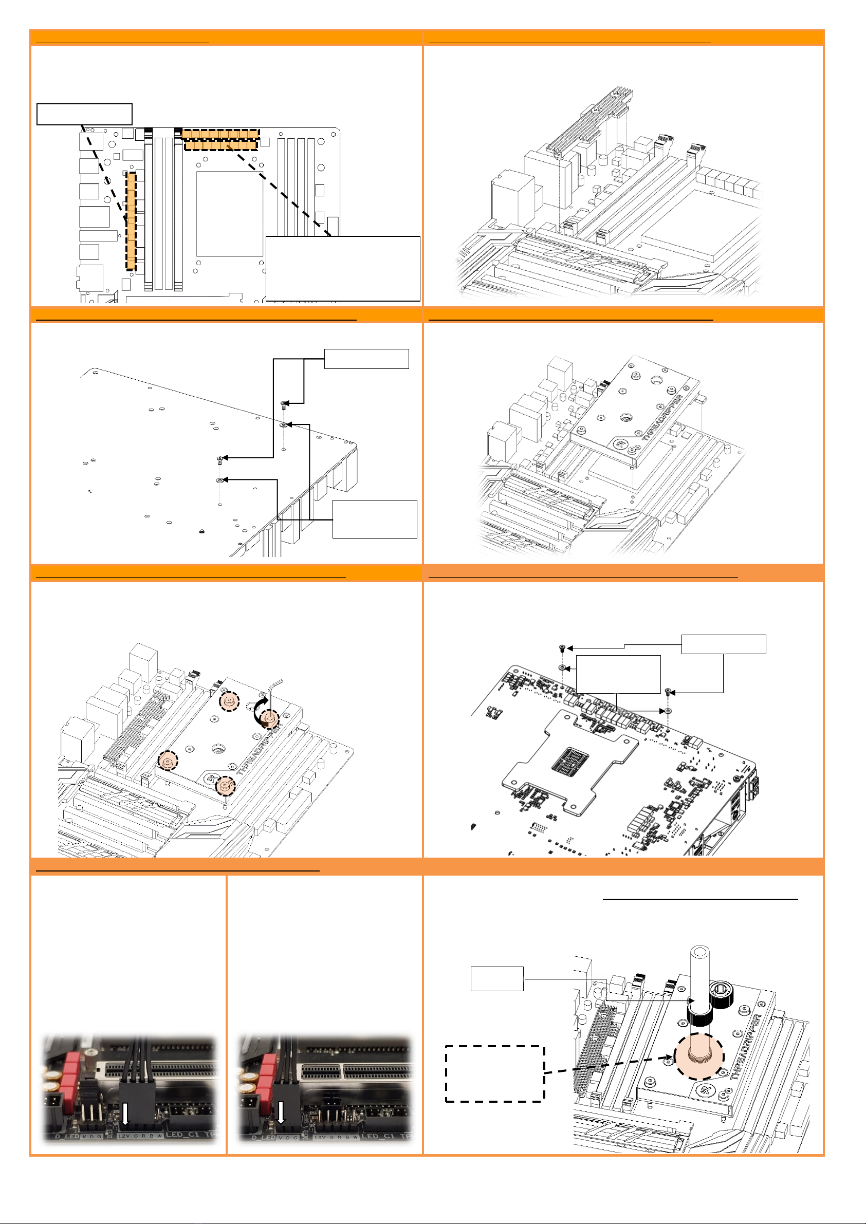
Place thermal pads on PCB as shown on the picture below.
PLEASE REMOVE THE PROTECTIVE FOIL FROM BOTH SIDES OF THE THERMAL
PADS PRIOR TO INSTALLATION!
STEP 7: PLACING THERMAL PADS
STEP 8: PLACING A HEATSINK TO THE MOTHERBOARD
Place the Heatsink gently to the motherboard as shown on the picture below; make
sure that mounting holes are aligned.
STEP 8.1: ATTACHING THE HEATSINK TO THE MOTHERBOARD
STEP 9: PLACING A BLOCK ON TO THE MOTHERBOARD
Before you fasten the screws please make sure that mounting holes on the
motherboard's circuit board are aligned with the heatsink.
Place the EK-FB GA X399 GAMING RGB Monoblock gently to the motherboard or vice
versa (as shown on picture below). Make sure that mounting holes are aligned.
STEP 9.1: ATTACHING A BLOCK ON TO THE MOTHERBOARD
STEP 9.2: ATTACHING A BLOCK ON TO THE MOTHERBOARD
Prior to fastening the screws please make sure the mounting holes on the
motherboard’s circuit board are aligned with the water block. Secure top 4 (four)
nickel screws with enclosed 2,5mm Allen key. Tighten screws diagonally and evenly
till the end of the thread. Do not use excessive force when tightening the screws!
Prior to fastening the screws please make sure the mounting holes on the
motherboard’s circuit board are aligned with the water block. Use 2 (two) M2,5x5 AX1
screws with M2.5 PVC washers. Tighten the screws evenly. Do not use excessive force
when tightening the screws!
STEP 10: CONNECTING THE RGB LED STRIP (optional)
CONNECT THE RGB LED (RGB LED with 4
wires):
Plug the 4-pin connector from Monoblock
RGB LED strip to the LED_C1 on the
motherboard. Please ensure that the
arrow indicated on the connector is
plugged into the +12V line as indicated
on your motherboard. Failure to do so
will damage your motherboard or LED
strip. You should leave the final pin,
marked as “W”, empty.
CONNECT THE D-RGB LED (LED with 3
wires):
5V D-RGB LED is enclosed with your
monoblock. If you swap the LED strip,
plug the 3-pin connector from Monoblock
D-RGB LED strip to the D_LED header on
the motherboard. Please ensure that the
arrow indicated on the connector is
plugged into the V line as indicated on
your motherboard. Failure to do so will
damage your motherboard or LED strip.
For the EK-FB GA X399 GAMING Monoblock series water block to operate properly the
lower G1/4 port of the water block MUST BE USED AS THE INLET PORT. EK
recommends the use of EK-ACF fittings. When using fittings other than EK-ACF series
please use hose clamps or appropriate substitute to secure the tubing to the barb. The
use of biocide containing and corrosion inhibiting coolant is always recommended for
any liquid cooling system.
Place 1mm thermal pad in
large strip over marked area
and make sure all mosfet chips
and inductor coils are covered.
2mm thermal pad
M2.5x5 screws
M2.5 PVC
washers
M2.5x5 screws
M2.5 PVC
washers
Tubing
IMPORTANT: USE
THIS OPENING AS
AN INLET PORT!