Abatron BDI2000 User manual

bdi
HCI
BDM interface for HI-WAVE™ Debugger
CPU16/32
User Manual
Manual Version 1.11 for BDI2000
© 1992-2001 ABATRON AG

bdi
HCI
BDM interface for HI-WAVE™ Debugger, BDI2000 (CPU16/32) User Manual 2
© Copyright 1992-2001 by ABATRON AG V 1.11
1 Introduction .................................................................................................................................3
1.1 BDI2000.................................................................................................................................3
2 Installation ...................................................................................................................................4
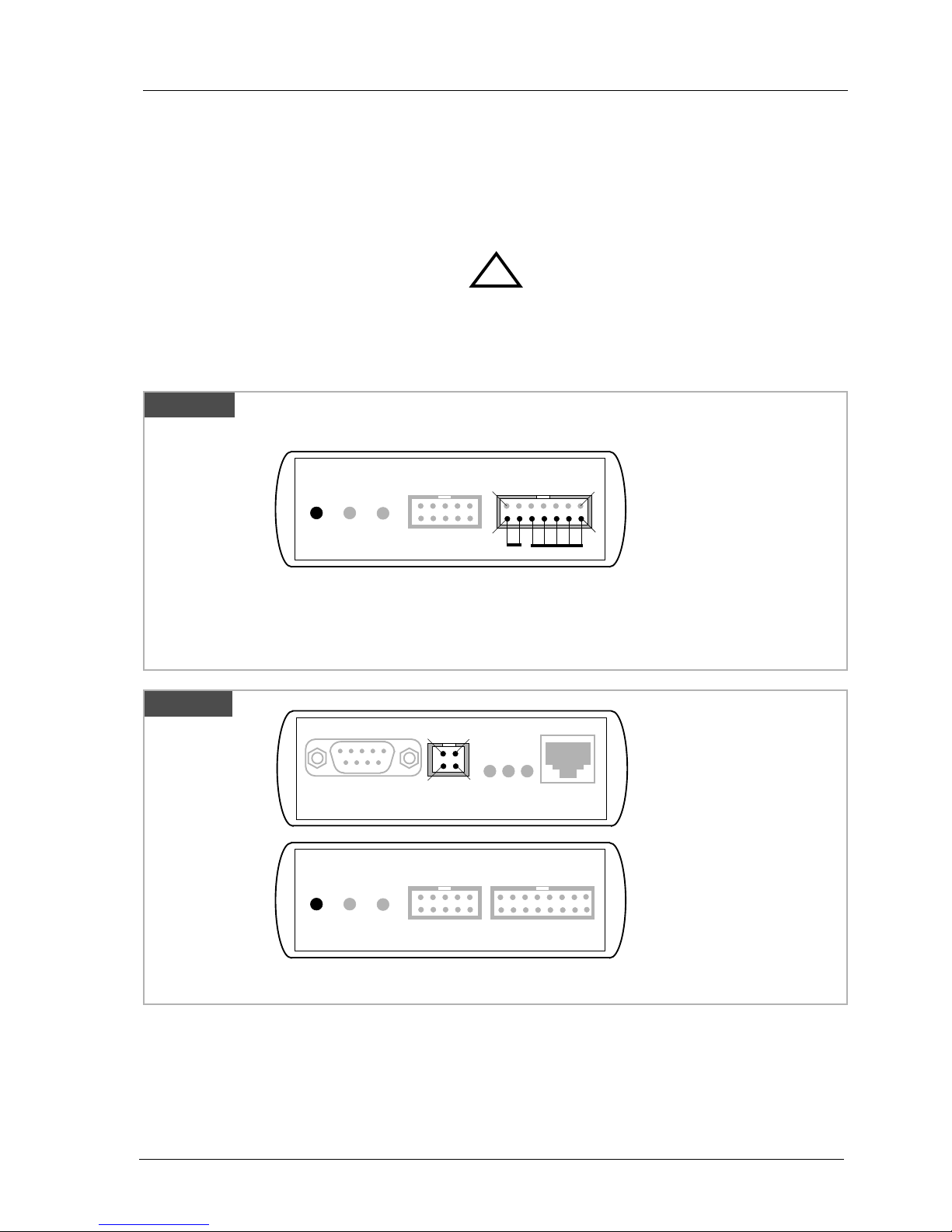
2.1 Connecting the BDI2000 to Target.........................................................................................4
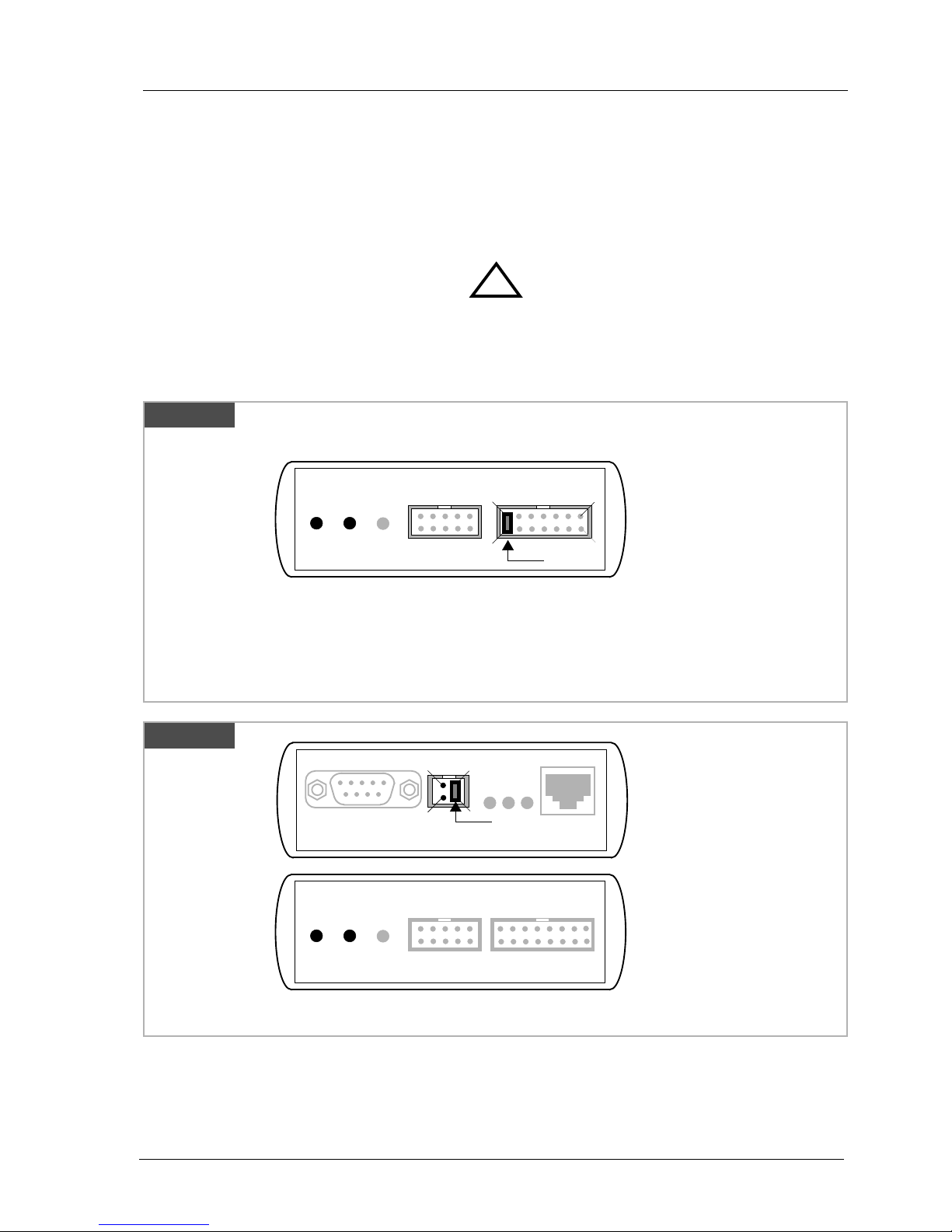
2.1.1 Changing Target Processor Type .................................................................................6
2.2 Connecting the BDI2000 to Power Supply.............................................................................7
2.2.1 External Power Supply.................................................................................................7
2.2.2 Power Supply from Target System ...............................................................................8
2.3 Status LED «MODE».............................................................................................................9
2.4 Connecting the BDI2000 to Host.........................................................................................10
2.4.1 Serial line communication..........................................................................................10
2.4.2 Ethernet communication ............................................................................................11
2.5 Installation of the Configuration Software............................................................................12
2.6 Configuration .......................................................................................................................13
2.6.1 BDI2000 Setup/Update..............................................................................................13
3 Init List........................................................................................................................................15
4 BDI working modes...................................................................................................................16
4.1 Startup Mode.......................................................................................................................17
4.1.1 Startup mode RESET ................................................................................................17
4.1.2 Startup Mode STOP...................................................................................................18
4.1.3 Startup mode RUN.....................................................................................................18
4.2 Breakpoint Mode .................................................................................................................18
4.2.1 Breakpoint Mode FREEZED......................................................................................19
4.2.2 Breakpoint Mode LOOP.............................................................................................19
4.3 Workspace...........................................................................................................................21
4.4 Terminal Data.......................................................................................................................22
5 Working with HI-WAVE..............................................................................................................23
5.1 Setup ...................................................................................................................................23
6 External Break Inputs ...............................................................................................................24
7 Specifications............................................................................................................................26
7.1 BDI2000...............................................................................................................................26
8 Environmental notice................................................................................................................27
9 Declaration of Conformity (CE)................................................................................................27
10 Warranty...................................................................................................................................28
Appendices
A Troubleshooting........................................................................................................................29
B Maintenance..............................................................................................................................30
B 1 BDI2000 ..............................................................................................................................30
C Trademarks................................................................................................................................32

bdi
HCI
BDM interface for HI-WAVE™ Debugger, BDI2000 (CPU16/32) User Manual 3
© Copyright 1992-2001 by ABATRON AG V 1.11
1 Introduction
The BDI2000 adds Background Debug Mode features to the HI-WAVE debugger environment.With
the BDI2000, you control and monitor the microcontroller solely through the stable on-chip debugging
services.You won’t waste time and target resources with a software ROM monitor, and you eliminate
the cabling problems typical of ICE’s. This combination runs even when the target system crashes
and allows developers to continue investigating the cause of the crash.
A RS232 interface with a maximum of 115 kBaud and a 10Base-T Ethernet interface is available for
the host interface.
The bdiHCI setup software is used to update the firmware and to configure the BDI2000 so it works
with the HI-WAVE debugger.
1.1 BDI2000
The BDI2000 is a processor system in a small box.It implements the interface between the BDM pins
of the target CPU and a 10Base-T Ethernet / RS232 connector.BDI2000 is powered by a MC68360,
512Kbyte RAM and a flash memory of 1024Kbyte. As a result of consistent implementation of lasted
technology, the BDI2000 is optimally prepared for further enhancements.The firmware and the pro-
grammable logic of the BDI2000 can be updated by the user with a simple Windows based configu-
ration program.The BDI2000 supports 1.8 – 5.0 Volts target systems (3.0 – 5.0 Volts target systems
with Rev. A/B).
PC Host
HI-WAVE
BDI2000
AA
AAbb
bbaa
aattttrr
rroo
oonn
nn AA
AAGG
GG SS
SSww
wwiiiiss
ssss
ss MM
MMaa
aadd
ddeeee
Target System
BDM Interface
Ethernet (10 BASE-T)
BDI2000
AA
AAbb
bbaa
aattttrr
rroo
oonn
nn AA
AAGG
GG SS
SSww
wwiiiiss
ssss
ss MM
MMaa
aadd
ddeeee
Target System
BDM Interface
RS232
CPU
16/32
CPU
16/32

bdi
HCI
BDM interface for HI-WAVE™ Debugger, BDI2000 (CPU16/32) User Manual 4
© Copyright 1992-2001 by ABATRON AG V 1.11
2 Installation
2.1 Connecting the BDI2000 toTarget
The cable to the target system is a ten pin flat ribbon cable. In case where the target system has an
appropriate connector, the cable can be directly connected.The pin assignment is in accordance with
the Motorola specification.
In order to ensure reliable operation of the BDI (EMC, runtimes, etc.) the target cable length must not
exceed 20 cm (8").
For BDI MAIN / TARGET A connector signals see table on next page.
!
BDI TRGT MODE BDI MAIN BDI OPTION
Target Connector
BDI2000
AA
AAbb
bbaa
aattttrr
rroo
oonn
nn AA
AAGG
GG SS
SSww
wwiiiiss
ssss
ss MM
MMaa
aadd
ddeeee
Target System
CPU
16/32
9
1
10 2
The green LED «TRGT» marked light up when target is powered up
1 - NOT USED
2 - BERR
3 - GROUND
4 - BKPT / DSCLK
5 - GROUND
6 - FREEZE
7 - RESET
8 - IFETCH / DSI
9 - Vcc Target
10 - IPIPE / DSO
19
210
Rev. A
Target Connector
BDI2000
AA
AAbb
bbaa
aattttrr
rroo
oonn
nn AA
AAGG
GG SS
SSww
wwiiiiss
ssss
ss MM
MMaa
aadd
ddeeee
Target System
CPU
16/32
The green LED «TRGT» marked light up when target is powered up
1 - NOT USED
2 - BERR
3 - GROUND
4 - BKPT / DSCLK
5 - GROUND
6 - FREEZE
7 - RESET
8 - DSDI
9 - Vcc Target
10 - IPIPE / DSO
19
210
BDI TRGT MODE TARGET A TARGET B
9 1
10 2
Rev. B/C

bdi
HCI
BDM interface for HI-WAVE™ Debugger, BDI2000 (CPU16/32) User Manual 5
© Copyright 1992-2001 by ABATRON AG V 1.11
BDI MAIN /TARGET A Connector Signals:
All the pins except pin 1need to be connected to the target system for the debug operation.
Pin Name Describtion
1 --- Not used.
2 BERR
BUS ERROR
Active-low input to the MCU.
Signals an invalid bus operation attempt.
3+5 GROUND
SYSTEM GROUND
4 BKPT / DSCLK
BREAKPOINT
For normal modes, active-low input to the MCU.
Signals a hardware breakpoint.
DEVELOPMENT SERIAL CLOCK
For background debug mode, serial input clock signal to the MCU.
6 FREEZE
FREEZE
Active-high output from the MCU.Indicates that the MCU has acknowledged a breakpoint
and that it has entered background debug mode.
7 RESET
RESET
Active-low, open-drain, signal to start a system reset.
8 IFETCH / DSI
INSTRUCTION FETCH
For normal modes, output signal from the MCU.
Indicates instruction pipeline activity.
DATA SERIAL IN
For background debug mode, serial data input signal to the MCU.
9 Vcc Target
1.8 – 5.0V:
This is the target reference voltage.It indicates that the target has power and it is also used
to create the logic-level reference for the input comparators.It also controls the output logic
levels to the target.It is normally fed from Vdd I/O on the target board.
3.0 – 5.0V with Rev. A/B :
This input to the BDI2000 is used to detect if the target is powered up.If there is a current
limiting resistor between this pin and the target Vdd, it should be 100 Ohm or less.
10 IPIPE / DSO
INSTRUCTION PIPE
For normal modes, output signal from the MCU.
Indicates instruction pipeline activity.
DATA SERIAL OUT
For background debug mode, serial data output from the MCU.

bdi
HCI
BDM interface for HI-WAVE™ Debugger, BDI2000 (CPU16/32) User Manual 6
© Copyright 1992-2001 by ABATRON AG V 1.11
2.1.1 ChangingTarget ProcessorType
Before you can use the BDI2000 with an other target processor type (e.g.CPU32 <--> PPC), a new
setup has to be done (see Appendix A). During this process the target cable must be disconnected
from the target system.The BDI2000 needs to be supplied with 5 Volts via the BDI OPTION connec-
tor (Version A) or via the POWER connector (Version B). For more information see chapter 2.2.1
«External Power Supply».
To avoid data line conflicts, the BDI2000 must be disconnected from the target system while
programming the logic for an other target CPU.
!

bdi
HCI
BDM interface for HI-WAVE™ Debugger, BDI2000 (CPU16/32) User Manual 7
© Copyright 1992-2001 by ABATRON AG V 1.11
2.2 Connecting the BDI2000 to Power Supply
2.2.1 External Power Supply
The BDI2000 needs to be supplied with 5Volts (max. 1A) via the BDI OPTION connector (Rev. A) or
via POWER connector (Rev. B/C).The available power supply from Abatron (option) or the enclosed
power cable can be directly connected. In order to ensure reliable operation of the BDI2000, keep
the power supply cable as short as possible.
For error-free operation, the power supply to the BDI2000 must be between 4.75V and 5.25V DC.
The maximal tolerable supply voltage is 5.25 VDC. Any higher voltage or a wrong polarity
might destroy the electronics.
Please switch on the system in the following sequence:
• 1 --> external power supply
• 2 --> target system
!
BDI TRGT MODE BDI MAIN BDI OPTION
13
1
14 2
BDI OPTION
1 - NOT USED
2 - GROUND
3 - NOT USED
4 - GROUND
5 - NOT USED
6 - GROUND
7 - NOT USED
8 - GROUND
9 - NOT USED
10 - GROUND
11 - NOT USED
12 - Vcc (+5V)
13 - Vcc Target (+5V)
14 - Vcc (+5V)
Vcc GND
Connector
The green LED «BDI» marked light up when 5V power is connected to the BDI2000
Rev. A
BDI TRGT MODE TARGET A TARGET B
POWER
1 - Vcc (+5V)
2 - VccTGT
3 - GROUND
4 - NOT USED
Connector
The green LED «BDI» marked light up when 5V power is connected to the BDI2000
RS232 POWER LI TX RX 10 BASE-T
1 Vcc
2
GND 3
4
Rev. BVersion
Rev. B/C

bdi
HCI
BDM interface for HI-WAVE™ Debugger, BDI2000 (CPU16/32) User Manual 8
© Copyright 1992-2001 by ABATRON AG V 1.11
2.2.2 Power Supply fromTarget System
The BDI2000 needs to be supplied with 5 Volts (max.1A) via BDI MAIN target connector (Rev.A) or
via TARGET A connector (Rev. B/C).This mode can only be used when the target system runs with
5V and the pin «Vcc Target» is able to deliver a current up to 1A@5V. For pin description and layout
see chapter 2.1 «Connecting the BDI2000 toTarget».Insert the enclosed Jumper as shown in figure
below. Please ensure that the jumper is inserted correctly.
For error-free operation, the power supply to the BDI2000 must be between 4.75V and 5.25V DC.
The maximal tolerable supply voltage is 5.25 VDC. Any higher voltage or a wrong polarity
might destroy the electronics.
!
BDI TRGT MODE BDI MAIN BDI OPTION
13
1
14 2
BDI OPTION
Connector
The green LEDs «BDI» and «TRGT» marked light up when target is powered up
Jumper
and the jumper is inserted correctly
1 - NOT USED
2 - GROUND
3 - NOT USED
4 - GROUND
5 - NOT USED
6 - GROUND
7 - NOT USED
8 - GROUND
9 - NOT USED
10 - GROUND
11 - NOT USED
12 - Vcc (+5V)
13 - Vcc Target (+5V)
14 - Vcc BDI2000 (+5V)
Rev. A
BDI TRGT MODE TARGET A TARGET B
POWER
1 - Vcc BDI2000 (+5V)
2 - Vcc Target (+5V)
3 - GROUND
4 - NOT USED
Connector
RS232 POWER LI TX RX 10 BASE-T
1
2
3
4
The green LEDs «BDI» and «TRGT» marked light up when target is powered up
and the jumper is inserted correctly
Jumper
Rev. B/C

bdi
HCI
BDM interface for HI-WAVE™ Debugger, BDI2000 (CPU16/32) User Manual 9
© Copyright 1992-2001 by ABATRON AG V 1.11
2.3 Status LED «MODE»
The built in LED indicates the following BDI states:
MODE LED BDI STATES
OFF The BDI is ready for use, the firmware is already loaded.
ON The power supply for the BDI2000 is < 4.75VDC.
BLINK The BDI «loader mode» is active (an invalid firmware is loaded or loading firmware is active).
BDI TRGT MODE BDI MAIN BDI OPTION
BDI TRGT MODE TARGET A TARGET B
Rev. A
Rev. B/C

bdi
HCI
BDM interface for HI-WAVE™ Debugger, BDI2000 (CPU16/32) User Manual 10
© Copyright 1992-2001 by ABATRON AG V 1.11
2.4 Connecting the BDI2000 to Host
2.4.1 Serial line communication
The host is connected to the BDI through the serial interface (COM1...COM4).The communication
cable between BDI and Host is a serial cable (RXD / TXD are crossed).There is the same connector
pinout for the BDI and for the Host side (Refer to Figure below).
RS232 Connector
(for PC host)
BDI2000
AA
AAbb
bbaa
aattttrr
rroo
oonn
nn AA
AAGG
GG SS
SSww
wwiiiiss
ssss
ss MM
MMaa
aadd
ddeeee
Target System
RS232
RS232 LI TX RX 10 BASE-T
54321
9876
PC Host
1 - NC
2 - RXD data from host
3 - TXD data to host
4 - NC
5 - GROUND
6 - NC
7 - NC
8 - NC
9 - NC
CPU
16/32
Rev. A
RS232 Connector
(for PC host)
BDI2000
AA
AAbb
bbaa
aattttrr
rroo
oonn
nn AA
AAGG
GG SS
SSww
wwiiiiss
ssss
ss MM
MMaa
aadd
ddeeee
Target System
RS232
PC Host
1 - NC
2 - RXD data from host
3 - TXD data to host
4 - NC
5 - GROUND
6 - NC
7 - NC
8 - NC
9 - NC
CPU
16/32
Rev. B/C
RS232 POWER LI TX RX 10 BASE-T
54321
9876

bdi
HCI
BDM interface for HI-WAVE™ Debugger, BDI2000 (CPU16/32) User Manual 11
© Copyright 1992-2001 by ABATRON AG V 1.11
2.4.2 Ethernet communication
The BDI2000 has a built-in 10 BASE-T Ethernet interface (see figure below). Connect an UTP (Un-
shilded Twisted Pair) cable to the BD2000. For thin Ethernet coaxial networks you can connect a
commercially available media converter (BNC-->10 BASE-T) between your network and the
BDI2000. Contact your network administrator if you have questions about the network.
The following explains the meanings of the built-in LED lights:
LED Name Description
LI Link When this LED light is ON, data link is successful between the UTP
port of the BDI2000 and the hub to which it is connected.
TX Transmit WhenthisLEDlightBLINKS,dataisbeingtransmittedthrough the UTP
port of the BDI2000
RX Receive When this LED light BLINKS, data is being received through the UTP
port of the BDI2000
10 BASE-T
PC Host
Target System
Ethernet (10 BASE-T)
1 - TD+
2 - TD-
3 - RD+
4 - NC
5 - NC
6 - RD-
7 - NC
8 - NC
Connector
CPU
16/32
RS232 LI TX RX 10 BASE-T
BDI2000
AA
AAbb
bbaa
aattttrr
rroo
oonn
nn AA
AAGG
GG SS
SSww
wwiiiiss
ssss
ss MM
MMaa
aadd
ddeeee
18
RS232 POWER LI TX RX 10 BASE-T
Rev. A
Rev. B/C
18

bdi
HCI
BDM interface for HI-WAVE™ Debugger, BDI2000 (CPU16/32) User Manual 12
© Copyright 1992-2001 by ABATRON AG V 1.11
2.5 Installation of the Configuration Software
On the enclosed diskette you will find the BDI configuration software and the firmware required for
the BDI. Copy all these files to a directory on your hard disk.
The following files are on the diskette:
b20c32.exe Configuration program
b20c32.hlp Helpfile for the configuration program
b20c32.cnt Help contents file
b20c32fw.xxx Firmware for BDI2000 for CPU16 and CPU32 targets
c32jed20.xxx JEDEC file for the BDI2000 (Rev. A/B) logic device programming
c32jed21.xxx JEDEC file for the BDI2000 (Rev. C) logic device programming
bdidll16.dll BDI Data Link Layer DLL (16bit version) for HI-CROSS
bdidll32.dll BDI Data Link Layer DLL (32bitVersion) for HI-WAVE onWindows 95 / NT
bdiifc32.dll BDI Interface DLL (32bit version)
*.bdi Configuration Examples
termbgnd.c16 Terminal I/0 module for CPU16
termbgnd.c32 Terminal I/0 module for CPU32
Example of an installation process:
• Copy the entire contents of the enclosed diskette into a directory on the hard disk.
•You may create a new shortcut to the b20c32.exe configuration program.

bdi
HCI
BDM interface for HI-WAVE™ Debugger, BDI2000 (CPU16/32) User Manual 13
© Copyright 1992-2001 by ABATRON AG V 1.11
2.6 Configuration
Before you can use the BDI together with the debugger, the BDI must be configured.Use the
SETUP
menu and follow the steps listed below:
• Load or update the firmware / logic, store IP address -->
Firmware
• Set the communication parameters between Host and BDI -->
Communication
• Setup an initialization list for the target processor -->
Initlist
• Select the working mode -->
Mode
• Transmit the configuration to the BDI -->
Mode Transmit
For information about the dialogs and menus use the help system (F1).
2.6.1 BDI2000 Setup/Update
First make sure that the BDI is properly connected (see Chapter 2.1 to 2.4).The BDI must be con-
nected via RS232 to the Windows host.
To avoid data line conflicts, the BDI2000 must be disconnected from the target system while
programming the logic for an other target CPU (see Chapter 2.1.1).
The following dialogbox is used to check or update the BDI firmware and logic and to set the network
parameters.
dialog box «BDI2000 Update/Setup»
The following options allow you to check or update the BDI firmware and logic and to set the network
parameters:
Channel Select the communication port where the BDI2000 is connected during
this setup session.
Baudrate Select the baudrate used to communicate with the BDI2000 loader during
this setup session.
!

bdi
HCI
BDM interface for HI-WAVE™ Debugger, BDI2000 (CPU16/32) User Manual 14
© Copyright 1992-2001 by ABATRON AG V 1.11
Connect Click on this button to establish a connection with the BDI2000 loader.
Once connected, the BDI2000 remains in loader mode until it is restarted
or this dialog box is closed.
Current Press this button to read back the current loaded BDI2000 software and
logic versions. The current loader, firmware and logic version will be dis-
played.
Update This button is only active if there is a newer firmware or logic version
present in the execution directory of the BDI setup software. Press this
button to write the new firmware and/or logic into the BDI2000 flash mem-
ory / programmable logic.
IP Address Enter the IP address for the BDI2000.
Use the following format: xxx.xxx.xxx.xxxe.g.151.120.25.101
Ask your network administrator for assigning an IP address to this
BDI2000. Every BDI2000 in your network needs a different IP address.
Subnet Mask Enter the subnet mask of the network where the BDI is connected to.
Use the following format: xxx.xxx.xxx.xxxe.g.255.255.255.0
A subnet mask of 255.255.255.255 disables the gateway feature.
Ask your network administrator for the correct subnet mask.
Default Gateway Enter the IP address of the default gateway. Ask your network administra-
tor for the correct gateway IP address. If the gateway feature is disabled,
you may enter 255.255.255.255 or any other value..
Transmit Click on this button to store the network configuration in the BDI2000 flash
memory.
In rare instances you may not be able to load the firmware in spite of a correctly connected BDI (error
of the previous firmware in the flash memory).Before carrying out the following procedure,check
the possibilities in Appendix «Troubleshooting». In case you do not have any success with the
tips there, do the following:
• Switch OFF the power supply for the BDI and open the unit as
described in Appendix «Maintenance»
• Place the jumper in the «INIT MODE» position
• Connect the power cable or target cable if the BDI is powered
from target system
• Switch ON the power supply for the BDI again and wait until the
LED «MODE» blinks fast
• Turn the power supply OFF again
• Return the jumper to the «DEFAULT» position
• Reassemble the unit as described in Appendix «Maintenance»
INIT MODE
DEFAULT

bdi
HCI
BDM interface for HI-WAVE™ Debugger, BDI2000 (CPU16/32) User Manual 15
© Copyright 1992-2001 by ABATRON AG V 1.11
3 Init List
dialog box «Startup Init List»
In order to prepare the target for debugging, you can define an Initialization List.This list is stored in
the Flash memory of the BDI2000 and worked through every time the target comes out of reset.Use
it to get the target operational after a reset.The memory system is usually initialized through this list.
After processing the init list, the RAM used to download the application must be accessible.
Use on-line help (F1) and the supplied configuration examples on the distribution disk to get more
information about the init list.

bdi
HCI
BDM interface for HI-WAVE™ Debugger, BDI2000 (CPU16/32) User Manual 16
© Copyright 1992-2001 by ABATRON AG V 1.11
4 BDI working modes
dialog box «BDI Working Mode»
With this dialog box you can define how the BDI interacts with the target system.
Identification Enter a text to identify this setup.This text can be read by the debugger
with the appropriate Command.
Startup Startup mode defines how the BDI interacts with the target processor after
reset or power up.The options RESET, STOP or RUN can be selected.
Breakpoint Breakpoint mode defines how breakpoints are processed.The target pro-
cessor may be frozen (FREEZED option) or may be set to loop in an ex-
ception procedure (LOOP option) while the application software is halted.
CPU Type Select the approriate CPU type. For CPU32+ select CPU32.
CPU Clock Rate ... Enter the clock rate which the target CPU runs, after BDI has worked
through the init list. BDI selects the BDM communication speed based on
this parameter. If this parameter selects a CPU clock rate that is higher
than the real clock, BDM communication may fail.When selecting a clock
rate slower than possible, BDM communication still works but not as fast
as possible.
Workspace In all configurations except when «use no target resources» is activated,
BDI needs some target memory space.Enter here the start address of this
memory area.A maximum of 512 bytes is needed.
Vector base The BDI needs to know where the vector table is located. Enter here the
start address of the vector table.This address is automatically loaded into
the VBR register at startup time. The application should not change the
VBR unless «use no target resources» is selected.
Terminal Data Enter the start address for the data structure used to support the HI-
CROSS terminal function.This option is disabled when «use no target re-
sources» is selected. A value of 0 disables the terminal function.

bdi
HCI
BDM interface for HI-WAVE™ Debugger, BDI2000 (CPU16/32) User Manual 17
© Copyright 1992-2001 by ABATRON AG V 1.11
Loop Level Selects the priority level (interrupt priority mask) the application uses
when halted in LOOP mode. A level of 7 disables all interrupts when the
application is halted.The value CURRENT(default) means, the application
loops with the level currently active at the point where it is stopped.
use no target res... Check this switch if the BDI should not use any RAM or vectors in the tar-
get system. This option is only enabled when FREEZED is selected as
breakpoint mode. This mode is suitable for testing new hardware or de-
bugging custom exception routines.
Run Time When startup mode STOP is selected, this option allows to set the run
time after reset in milliseconds until the target CPU is stopped. Values
from 100 (0.1 sec) till 32000 (32 sec) are accepted.
SIM60 Breakpoint The internal breakpoint logic in a CPU with a SIM60 module (e.g.
MC68360) is supported and can be used to set breakpints on variable ac-
cesses or to set code breakpoints even when the code runs out of a read
only memory (e.g. Flash Device). Check this switch, if the SIM60 break-
point logic is present and should be used to support hardware break-
points. Only one hardware breakpoint can be set at the same time. In the
special case, when also «use no target resources» is checked, every code
breakpoint uses the SIM60 hardware. In this mode it is easy to work
through the code (even when stored in ROM) by simple mouse clicks to
the source code.
RegBase Enter the base address of the SIM60 registers.For example, enter 101000
if MBAR points to 100000 (all numbers in hexadecimal).
4.1 Startup Mode
Startup mode defines how the BDI interacts with the target system after a reset or power up
sequence.
4.1.1 Startup mode RESET
In this mode no ROM is required on the target system.The necessary initialization is done by the BDI
with the programmed init list.The following steps are executed by the BDI after system reset or
system power up:
• RESET and BKPT are activated on the target system.
• RESET is deactivated and the target system changes to background debug mode. If the
target system does not change to background debug mode, the BDI waits for a short time and
then activates the BERR line.
• Register DFC and SFC are set to supervisor data space.
• The BDI works through the initialization list and writes to the corresponding addresses.
• Depending on the break mode, the necessary vectors are set and help code is written into the
RAM on the target system.
The RESET mode is the standard working mode. Other modes are used in special cases (i.e.
applications in ROM, special requirements on the reset sequence...).

bdi
HCI
BDM interface for HI-WAVE™ Debugger, BDI2000 (CPU16/32) User Manual 18
© Copyright 1992-2001 by ABATRON AG V 1.11
4.1.2 Startup Mode STOP
In this mode the initialization code is in a ROM on the target system.The code in this ROM handles
base initialization and sets the stackpointer. At the end of the code, the initialization program enters
an endless loop until it is interrupted by the BDI.This mode is intended for special requirements on
the reset sequence or, if, for example, separate hardware needs to be initialized immediately.
In this mode the following steps are executed by the BDI after system reset or power up:
• RESET and BKPT are activated on the target system.
• RESET is deactivated and the target system changes to background debug mode. If the
target system does not change to background debug mode, the BDI waits for a short time and
then activates the BERR line.
• Register DFC and SFC are set to supervisor data space.
•The target CPU is started (the target starts at the address fetched when reading the start vec-
tor at address 0).
• The target system is working through the application code.
• After the programmed runtime, BKPT is activated and the target system changes to back-
ground debug mode. If the target system does not change to background debug mode, the
BDI waits for a short time and then activates the BERR line.
• The BDI works through the initialization list and writes the corresponding addresses.
• Depending on the break mode, the necessary vectors are set and support code is written into
the RAM on the target system.
4.1.3 Startup mode RUN
This mode is used to debug applications which are already stored in ROM.The application is started
normally and is stopped by the BDI if HALT is chosen within the HI-CROSS debugger.
In this mode, the following steps are executed by the BDI after system reset or power up:
• RESET and BKPT are activated on the target system.
• RESET is deactivated and the target system changes to background debug mode. If the
target system does not change to background debug mode, the BDI waits for a short time and
then activates the BERR line.
• Register DFC and SFC are set to supervisor data space.
•The target CPU is started (the target starts at the address fetched when reading the start vec-
tor at address 0).
• The target system is executing the application code.
• The application runs until the user chooses HALT in the HI-CROSS debugger.
• BKPT is activated on the target system, and the target system changes to background
debug mode. If the target system does not change to background debug mode, the BDI waits
for a short time and then activates the BERR line.
• Depending on the break mode, the necessary vectors are set and help code is written into the
RAM on the target system.
4.2 Breakpoint Mode
The use of breakpoints is only possible if the application code is stored in RAM (not in ROM) on the
target system.Depending on the selected breakpoint mode, breakpoint and single step functions are
implemented total differently.

bdi
HCI
BDM interface for HI-WAVE™ Debugger, BDI2000 (CPU16/32) User Manual 19
© Copyright 1992-2001 by ABATRON AG V 1.11
4.2.1 Breakpoint Mode FREEZED
In this mode breakpoints are implemented by replacing application code with the BGND instruction.
All the time the application is halted (i.e.caused by a breakpoint) the target processor remains
freezed.
For CPU32:
Single step is implemented by starting the target processor and immediately activating the BKPT line.
So the target processor will be frozen after executing exactly one instruction. All interrupts are dis-
abled during the execution of this single instruction.The status register (SR) is restored to the correct
value after single stepping an instruction. The BDI takes care of instructions that changes the SR
(e.g. RTE, MOVE to SR, ANDI to SR, ... ) or writes the SR value to memory / register (e.g. MOVE
from SR, TRAP, ...).
Note when using SIM60 breakpoint logic:
If the SIM60 breakpoint hardware is enabled and also «use no target resources» is checked, only
hardware breakpoints will be used. There is no code replacement and therefore, the code may be
stored in read only memory. Only the last set breakpoint will be active. The last set breakpoint can
be removed using the HI-CROSS Breakpoint menu.
For HC16:
Single step is implemented by starting the target processor and immediately activating the BKPT line.
So the target processor will be frozen after executing exactly one instruction. If there are pending in-
terrupts, this instruction may be the first instruction of the interrupt service routine and not the instruc-
tion currently pointed by the program counter (PC). In other words, single stepping steps into
exception processing. If this behavior is a problem, use LOOP mode instead.
4.2.2 Breakpoint Mode LOOP
In this mode breakpoints are implemented by replacing application code withTRAP#15 (CPU32)
respectively an illegal instruction (CPU16). A stopped application loops within an exception
procedure.The target processor is freezed only for short time periods (max 70us).The priority level
used when looping in the exception procedure can be defined using the option «Loop Level».
If you want to stop the hole application use Loop Level 7. If only the current task should be stopped,
use Loop Level CURRENT.
Single step is implemented by setting theTrace bit in the processor status register (CPU32) respec-
tively by setting breakpoint(s) at the instruction(s) immediately following the current instruction
(CPU16). So a single step steps always over the current instruction. If interrupts are pending, they
are served first without stopping the target processor. In other words, single stepping steps over ex-
ception processing.
Note for CPU32 systems:
In order to halt the application TRAP #1 is used.

bdi
HCI
BDM interface for HI-WAVE™ Debugger, BDI2000 (CPU16/32) User Manual 20
© Copyright 1992-2001 by ABATRON AG V 1.11
The following diagram shows the used universal exception procedure for CPU32 targets.May be this
helps you to understand how BDI works in LOOP mode.
Vectortable:
save all register
set SFC/DFC to
supervisor data space
write loop level
to status register
Test and clear
semaphore
restore all registers
enter BDM mode
(BGND instruction)
Acknowledge
flag cleared?
restart flag
set ?
set acknowledge flag
clear restart flag
RTE
no
yes
yes
no
Entry
BDI2000 firmware
BDM interrupt
read stackframe pointer
clear acknowledge flag
set restart flag
Target BDI2000
The application loops here
when stopped.
Also if interrupts are enabled
(Loop Level < 7), tasks with
lower priority will get no CPU
time because the stopped
task consumes it all.
set semaphore
set
cleared
Other manuals for BDI2000
10
Table of contents
Other Abatron Computer Accessories manuals