ABB Thomas & Betts Elastimold 252LRJS-IEC User manual

IS--1627
IS--252LRJS--IEC
Revision: 0
Page 1 of 5
Installation Instructions: 252LRJS--IEC
Deadbreak Elbow Connectors with Jacket Seal
CONTENTS: Elbow Connector Housing, Compression Lug, Probe, Probe Wrench, Lubricant, Hold--down Bail,
Installation Instructions.
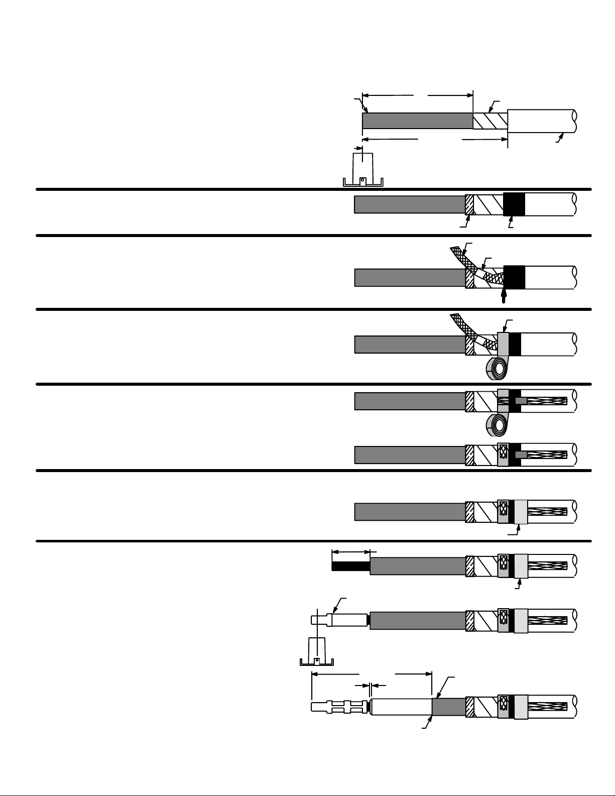
The 252LRJS is designed to terminate UD jacketed and non--jacketed cable having concentric neutral wires or copper tape
shielding. The elbow provides a voltage test point and an operating interface for connecting to an 12/20 (24)kV 250ampere
deadbreak bushing or accessory device. Designed with a fold down extension on the cable entrance for sealing to the jacket of
jacketed cable. When other types of UD cable are to be terminated, an appropriate Elastimold cable shield or grounding device
must be used.
DANGER
All apparatus must be de--energized during installation
or removal of part(s).
Do not touch or move energized products in the work
area.
These instructions do not attempt to provide for every
possible contingency.
Failure to follow these instructions will result in
damage to the product and serious or fatal injury.
This product should be installed only by competent
personnel trained in good safety practices involving
high voltage electrical equipment. These instructions
are not intended as a substitute for adequate training or
experience in such safety practices.
All apparatus must be installed and operated in
accordance with individual user, local and national
work rules and electrical standards.
For loadbreak products follow operating instructions.
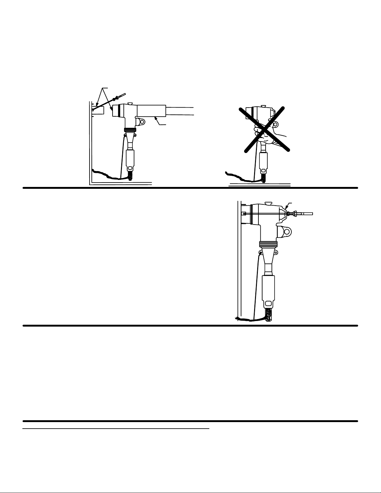
All deadbreak connectors must be de--energized before
operating. All 250A deadbreak connectors must be
mechanically secured with bails when connected.
If this product is supplied with a protective shipping
cover(s), remove this shipping cover(s) and replace
with the appropriate HV insulated cap(s) or
connector(s) before submerging or energizing the
circuit.
Inspect parts for damage, rating and compatibility with
mating parts.
Excess distortion of the assembled product may result
in its failure.
FOR MORE INFORMATION ON PARTS, INSTALLATION RATINGS AND COMPATIBILITY, CALL THE NEAREST ELASTIMOLD OFFICE.
Limited Warranty:
1. T&B warrants that its products will be free from defects in materials or workmanship for a period of two (2) years, except for tools which are warranted
separately (see warranty accompanying those products). Fisher Pierceproducts and ElastimoldReclosers are warranted for three years; and Joslyn
VBT and VBU capacitor switches are warranted for four years or 40,000 operations whichever occurs first. Upon prompt notification of a warranted defect,
T&B will, at its option, repair or replace the defective product.
2. In no event shall T&B be liable for any consequential, indirect or special damages, nor will T&B be liable for transportation, labor, or other charges arising
out of the removal or reinstallation of its products. Liability for breach of warranty is limited to the cost of repair or replacement of the warranted product
only.
3. Misuse, misapplication or modification of T&B products immediately voids all warranties.
THE WARRANTIES AND REMEDIES CONTAINED HEREIN ARE EXCLUSIVE AND ARE IN LIEU OF ALL OTHER WARRANTIES AND REMEDIES, INCLUDING
BUT NOT LIMITED TO ANY IMPLIED WARRANTIES OF MERCHANTABILITY AND FITNESS FOR A PARTICULAR PURPOSE, WHICH ARE SPECIFICALLY
DISCLAIMED.
IMPORTANT
1. Read entire installation instruction before starting.
2. Check contents of package to ensure they are complete
and undamaged.
3 Check elbow housing cable entrance size and
compression lug size to ensure proper fit with cable.
4. Check threads by threading probe into compression lug.
If resistance is encountered prior to full assembly, check
for damage and replace damaged component.
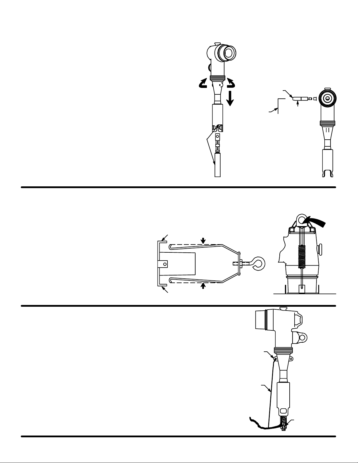
5. Unit Must be Bailed.
6. Have all required tools at hand and maintain cleanliness
throughout the procedure.
Compression Lug
Probe
Operating
Eye
ASSEMBLED ELBOW
Elbow Housing Test Point
Intergral Cable
Jacket Seal
Caution: If test point cap is not installed, lubricate cap and test point and install cap.
IS--1627
IS--252LRJS--IEC
Date: December 2017
Printed in U.S.A.
8155 T&B Boulevard, Memphis, Tennessee 38125
(800) 888--0211 Fax: (800) 888--0690

IS--1627
IS--252LRJS--IEC
Revision: 0
Page 2 of 5
STEP 1 CABLE TRAINING
1. Train cable to ensure slack for ease of operation.
2. An extra length of concentric neutral wires or grounding braid is needed to faciliate hotstick operation and connection of
the neutral to the tank ground. This can be accomplished by either of two methods: 1. Tape mark the bushing centerline
and pull extra cable to 24--26” beyond the bushing centerline; 2. Proceed to Step 1.D., connect the neutral wires to the
tank ground with a jumper or braid.
3. Unwrap the neutral wire back past the bushing centerline.
4. Cut excess cable squarely at the centerline of the bushing.
STEP 2A CABLE PREPARATION CONCENTRIC NEUTRAL WIRES
1. Wrap one strip of mastic, stretching slightly, around jacket.
2. Bend all of the neutral wires straight back over the mastic
and along the cable. Press the wires into the mastic.
3. Wrap the second strip of mastic completely around the
outer jacket, overlapping the neutral wires imbedded into
the first mastic strip. Use the third strip of mastic, if needed,
to build--up the outer diameter in the area of the first mastic
location. Cover all mastic with vinyl tape.
4. Remove insulation shield and insulation from the cable end.
Cut squarely taking care not to nick conductor.
5. Wire brush bare aluminum conductors and immediately place
compression lug over bushing. Rotate to spread inhibitor.
Position compression lug so the CONTACT THREADED
HOLE ALIGNS WITH THE BUSHING BORE. (Refer to crimp
chart packaged with compression lug for recommended crimp
tool information.) Start crimp at the crimp line mark. Rotate
180_each successive crimp. Carefully wipe excess inhibitor
from the outside of the lug and cable.
6. Remove insulation shield as shown. Bevel insulation end
1/8” max.
7. Thoroughly clean insulation to remove all traces of dirt or
excess inhibitor.
7---3/4”-- 8”
2---1/8”
Start Crimp Here
First Mastic
Align lug thread
to bushing bore
6---7/8”
1/8” Max.
Bevel
Insulation
Insulation
Shield
Straight, Smooth & Squared
Do not cut or nick insulation
Second Mastic
Insulation Shield
Imbed Wires into
First Mastic Strip
Outer
Jacket
Third Mastic
Vinyl Tape
Extra Length of Wires/Braid
24” -- 26”
Bushing
Centerline
Wires/Braid not shown
Bent Back for Clarity
7---3/4”-- 8”
Jacketed Cable

IS--1627
IS--252LRJS--IEC
Revision: 0
Page 3 of 5
STEP 2B CABLE PREPARATION FOR JACKED COPPER TAPE SHIELD CABLE
1. Cut the cable squarely at the centerline of the bushing.
2. Remove 8--1/2” (209mm) of the outer jacket.
3. Remove 7” (178mm) of the copper tape shield.
4. Wrap conductive copper tape around the edge to keep
the copper tape shield in place. Install the desired
product per the manufacturer’s instructions included
with the product. Apply one wrap of mastic, as shown.
Mastic
Conductive Copper Strip Mastic
5. Slightly flare the end of the braid with the solder block and
place it on the copper shield, flush against the cable jacket. Solder Block
Braided Copper Wire
Flush
6. Wrap the spring coil around braid and cable two
complete turns. Spring Coil
7. Bend braid back over the spring and wrap the remainder
of the spring coil around the braid and cable. Hand
tighten spring coil and secure the end of the coil with
a short piece of copper tape. Be sure the solder block of
braid is centered on top of the mastic tape.
8. Apply mastic over the braid, as shown.
9. Over wrap mastic with two half--lapped layers of vinyl tape.
10. Wrap the third piece of mastic around the cable entrance
of the connector being used. Over wrap mastic with two
half--lapped layers of vinyl tape.
Mastic/Vinyl Tape
11. Remove insulation shield and insulation from the cable
end. Cut squarely taking care not to nick conductor.
12. Position compression lug so the CONTACT THREADED
HOLE ALIGNS WITH THE BUSHING BORE. (Refer to
crimp chart packaged with compression lug for
recommended crimp tool information.) Start crimp at the
crimp line mark. Rotate 180_each successive crimp.
Carefully wipe excess inhibitor from the outside of the lug
and cable.
13. Remove insulation shield as shown. Bevel insulation
end 1/8” max.
14. Thoroughly clean insulation to remove all traces of dirt
or excess inhibitor.
8---1/4”
(209mm)
7”
(178mm) Copper Tape
Jacket
Bushing Centerline
Insulation
Shield
Mastic/Vinyl Tape
2---1/8”
Start Crimp Here
Align lug thread
to bushing bore
6---7/8”
1/8” Max.
Bevel
Insulation
Insulation Shield
Straight, Smooth & Squared
Do not cut or nick insulation

IS--1627
IS--252LRJS--IEC
Revision: 0
Page 4 of 5
STEP 3 ELBOW ASSEMBLY
1. Clean the cable insulation and inside the elbow housing
and lubricate with the lubricant supplied. DO NOT
SUBSTITUTE. Other lubricants may be harmful to this
product or its mating product(s). Keep insulation clean
of dirt and grime.
2. Slide the elbow connector onto the cable with a
back and forth twisting motion. Wipe off all excess
lubricant.
3. Align elbow with compression lug’s threaded hole.
4. Thread probe into lug by hand, taking care not to
cross--thread. Tighten with wrench until wrench
bends.
STEP 4 ASSEMBLE BAIL
Place hold--down bail in hold--down bracket.
Bracket Compress Bail &
Insert into Brackets
Bracket
Optional Bail Locator
STEP 5 CONCENTRIC NEUTRAL CONNECTION OR COPPER TAPE
1. Pull the hood over the concentric neutral seal area on
the cable by pulling the tabs and/or rolling the seal
down.
2. Using a separate copper wire (No. 14 AWG / 2.5mm)
or equivalent, insert one end through the grounding eye
on the elbow. Twist tightly taking care not to damage
the eye.
3. Connect copper braid and wire to ground using
appropriate connector. Provide adequate slack in
wires for elbow operation.
Wrench
Twist
Lubricate
Wrench Hole
Probe
Grounding Eye
To Ground
No. 14
Copper Wire
Copper Braid
to Ground

IS--1627
IS--252LRJS--IEC
Revision: 0
Page 5 of 5
STEP 6 CONNECT ELBOW AND BUSHING PLUG
1. Clean the receptacle portion of the elbow connector and the mating bushing and lubricate with the lubricant supplied.
LUBRICATE ONLY IF THE TRANSFORMER AND ELBOW ARE KNOWN TO BE DE--ENERGIZED.
2. Use a fully insulated hot stick to place the elbow on the bushing. DO NOT OPERATE BY HAND. DO NOT SEPARATE IF
ENERGIZED.
Hotstick
Clean and Lubricate only if known to be de--energized
STEP 7 BAIL ELBOW
1. Pull hold--down bail up over the crown or top of elbow
so that the eyebolt on the bail is directly over the
operating eye.
2. Tighten down on elbow locator by turning eyebolt in a
clockwise direction. Adjust the nut on the eyebolt
until it allows the eyebolt to seat securely in the locator.
The nut should act as a stop to prevent the eye
bolt from applying excessive force on the elbow. Once
the nut is in final position, it will not have to be
readjusted when removing and replacing elbow.
Operating Eye
VOLTAGE TEST
ELASTIMOLD connectors equipped with an integral capacitance test point can be used to establish whether or not the
circuit is energized. When using the test point, complete the following steps:
1. Remove test point cap with a hotstick. When removing cap, PEEL OFF AT AN ANGLE rather than pulling directly in line
with the test point assembly.
2. WARNING: THE VOLTAGE TEST POINT IS A CAPACITANCE DEVICE, IT IS NOT DIRECTLY CONNECTED TO THE
CONDUCTOR. Do not use conventional voltage measuring equipment. Follow the manufacturer’s directions for the
meter that is used. Test with a suitable sensing device, made for use with separable connectors manufactured with
capacitive test points, to determine if cable is energized. Contamination, moisture, dirt, etc. around the test point or use
of the wrong measuring equipment can provide a false “no voltage” indication on an energized elbow. To prevent
serious or fatal injury treat the elbow as energized until the “no voltage” test point indication is confirmed by other means.
3. After voltage detection has been made, clean the inside surface of the cap and lubricate with lubricant supplied;
replace it on the test point.
THOMAS & BETTS CORP. PROPRIETARY AND CONFIDENTIAL
BY ACCEPTANCE OF THIS DOCUMENT YOU AGREE THAT ALL RIGHTS TO THE DRAWINGS AND INFORMATION CONTAINED IN IT, AS WELL AS THE
SUBJECT MATTER AND ALL PROPRIETARY AND NOVEL FEATURES DISCLOSED, ARE OWNED BY THOMAS & BETTS CORPORATION (”THE COMPANY”
AND A MEMBER OF THE ABB GROUP) AND THAT DEVICES EMBODYING SUCH FEATURES OR INFORMATION DERIVED FROM THESE DRAWINGS WILL
NOT BE MANUFACTURED BY OR FOR YOU OR DISCLOSED TO OTHERS WITHOUT THE PRIOR EXPRESS WRITTEN CONSENT OF THE COMPANY.
THESE DRAWINGS ARE NOT TO BE COPIED OR REPRODUCED OR DISCLOSED TO OTHERS WITHOUT THE PRIOR EXPRESS WRITTEN CONSENT OF
THE COMPANY. ALL DRAWINGS AND INFORMATION ARE TO BE RETURNED TO UPON DEMAND OR UPON COMPLETION OF PURPOSE FOR WHICH
LENT. COPYRIGHT THOMAS & BETTS CORP. ALL RIGHTS RESERVED. ALL OTHER TRADEMARKS ARE THE PROPERTY OF THEIR RESPECTIVE
OWNERS.
This manual suits for next models
4
Table of contents
Other ABB Cables And Connectors manuals
Popular Cables And Connectors manuals by other brands

Advanced Bionics
Advanced Bionics Naida Cl CI-5415 Instructions for use

Philips
Philips Sonicare 300 SerieS Information

Staubli
Staubli MC4-Evo 2 Series Assembly instructions

Tripp Lite
Tripp Lite N320-01M-RD Specification sheet

red lion
red lion CPNL Series manual

Tripp Lite
Tripp Lite f007-015 Product specifications