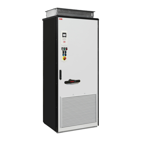
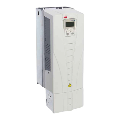
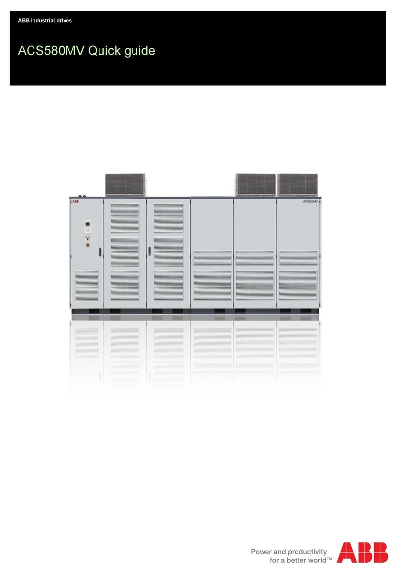
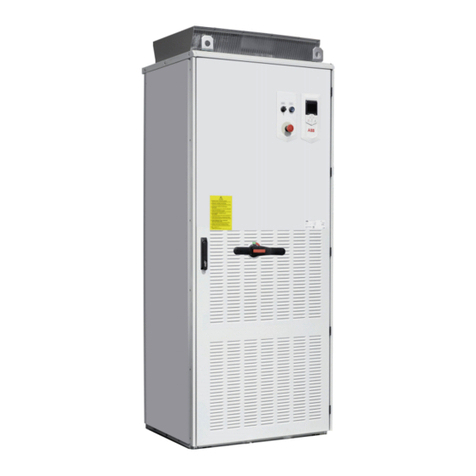
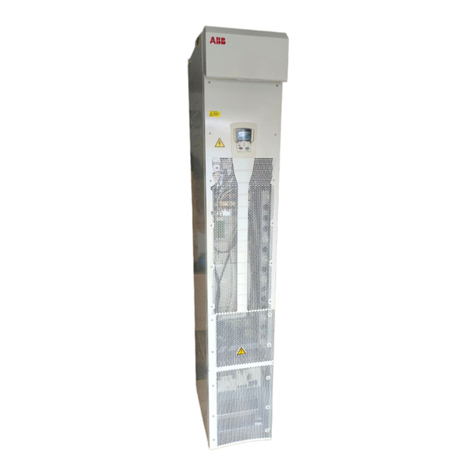
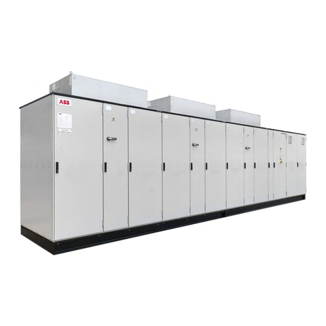
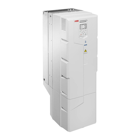
ABB ACS560 Installation manual


EN - Quick installation and start-up
guide
This guide briefly instructs how to install and start-up the ACS560 drive of all frame sizes
(R0...R8). For complete information, see the drive ACS560 standard control program firmware
manual (3AXD50000044997[English]) and ACS560 drives (0.75 to 160 kW, 1.0 to 215 hp)
hardware manual (3AXD50000044998[English]).
General considerations
■Obey the safety instructions
WARNING! Obey these instructions. If you ignore them, injury or death, or damage
to the equipment can occur.
• If you are not a qualified electrician, do not do electrical installation work.
• Do not work on the drive, motor cable or motor when main power is applied.
If the drive is already connected to the input power, wait for 5 minutes after
disconnecting the input power.
• Do not work on the control cables when power is applied to the drive or to the
external control circuits.
• Use the lifting eyes of the drive when you lift the drive. Do not tilt the drive.
The drive is heavy and its center of gravity is high. An overturning drive can
cause physical injury.
• Make sure that debris from borings and grindings does not enter the drive
when installing.
•Make sure that the floor below the drive and the wall where the drive is installed
are non-flammable.
■Reform the capacitors
Reform the capacitors if the drive is stored for a year or more.
The manufacturing date is on the type designation label which is attached to the drive. The
serial number format MYYWWRXXXX represents the month, year and the week.
YY: 13, 14, 15, … for 2013, 2014, 2015, …
WW: 01, 02, 03, … for week 1, week 2, week 3, …
For information on reforming the capacitors, see Converter module capacitor reforming
instructions (3BFE64059629 [English]).
■Select the power cables
Size the power cables according to local regulations to carry the nominal current given on
the type designation label of your drive. See Ratings (page 93).
■Ensure the cooling
The maximum ambient temperature without derating is:
• 50 °C (+122 °F) for R0...R2 frames
EN - Quick installation and start-up guide 3
EN
HI

• 40°C (+104 °F) for R3...R8 frames
No condensation or frost is allowed. For more information on the ambient temperature, see
the hardware manual.
■Protect the drive and input power cable
If you use gG fuses, make sure that the operating time of the fuse is below 0.5 seconds.
Follow the local regulations.
4 EN - Quick installation and start-up guide
EN
HI

Install the drive
You can install the drive
• to a DIN installation rail with integrated lock. This method applies to frames R0...R2
only.
or
• with screws to a suitable surface (wall or assembly plate). This method applies to all
frames R0...R8.
■Required tools for installing the drive
• A drill and suitable drill bits.
• Screwdriver (Standard, Phillips head, and Torx)
• wrench with suitable bits and sizes (appropriate for the installation hardware used). See
the required screw sizes in below installation instructions
• A tape measure and spirit level.
• Personal protective equipment.
■Installing a drive to DIN installation rail (frames R0...R2 only)
1. On the top center of the drive move the locking part to the left.
2. Push and hold the locking button down.
3. Put the top tabs on the drive onto the top edge of the DIN rail.
4. Put the drive against the bottom edge of the DIN installation rail.
5. Release the locking button.
6. Move the locking part to the right.
7. Make sure the drive is installed correctly.
■Removing drive from the DIN installation rail (frames R0...R2 only)
To remove the drive, open the locking part using a flat-head screwdriver.
EN - Quick installation and start-up guide 5
EN
HI

■Installing a drive with screws (frames R0...R8)
All drives of frames R0...R8 can be installed on the wall with screws. See the required screw
sizes in below mounting dimensions table. See also Dimensions, weights and free space
requirements (page 99)
WARNING!
The drive module (frames R6...R8) is heavy (45 to 70 kg). Consider the following:
• Use a suitable lifting device.
• Do not lift the module manually.
• Make sure that the wall and the fixing devices can carry the weight. See data
in the table below.
1. Mark the mounting hole locations using the mounting template included in the package.
Mounting dimensionsMounting template
R8R7R6R5R4R3R2R1R0Frames
M8M6M5Screws
(mm)
658583531581619473191a
701623571612-b
2632452131601487550
-75d
20075e
70.055.045.028.023.014.867.544.574.47Weight
(kg)
2. Drill the mounting holes.
3. Tighten the screws into the mounting holes.
4. Position the drive onto the screws on the wall.
5. Tighten the mounting screws.
6 EN - Quick installation and start-up guide
EN
HI

See the example of mounting screws in frame R0
6. Frames R5...R8 only: Remove the front cover with fastening screws (6a), move the
cover to the top side (6b) and then up (6c).
7. Frames R5...R8 only: Attach the cable conduit box to the drive frame.
Note:
Cable conduit box is optional and is not part of standard delivery.
8. Frames R5...R8 only: Tighten the box screws: two at the top and four at the bottom.
EN - Quick installation and start-up guide 7
EN
HI

Checking the insulation of the motor and motor cable
Obey the safety instructions of the drive. If you ignore them, injury or death,
or damage to the equipment can occur.
If you are not a qualified electrician, do not do installation or maintenance
work.
1. Stop the drive and do the steps in section Electrical safety precautions before you start
the work.
2. Check that the motor cable is disconnected from the drive output terminals U2, V2 and
W2.
3. Measure the insulation resistance between the phase conductors and then between
each phase conductor and the Protective Earth conductor. Use a measuring voltage of
1000 V DC. The insulation resistance of an ABB motor must exceed 100 Mohm
(reference value at 25 °C or 77 °F). For the insulation resistance of other motors, consult
the manufacturer’s instructions.
Note:
Moisture inside the motor casing reduces the insulation resistance. If moisture is
suspected, dry the motor and repeat the measurement.
1000 V DC,
>100 Mohm
U1-V1, U1-W1, V1-W1
U1-PE, V1-PE, W1-PE
M
3~
U1
V1
W1 PE
ohm
ohm
8 EN - Quick installation and start-up guide
EN
HI

Connecting the power cables
■Connection diagram
For alternatives, see hardware manual.1
Use a separate grounding PE cable (2a) or a cable with a separate PE conductor (2b) if the conductivity
of the shield does not meet the requirements for the PE conductor (see hardware manual).
2
360-degree grounding is recommended if shielded cable is used. Ground the other end of the input cable
shield or PE conductor at the distribution board.
3
360-degree grounding is required.4
External brake resistor (for frames R4...R8 only).5
Use a separate grounding cable if the shield does not meet the requirements of IEC 61439-1 and there
is no symmetrically constructed grounding conductor in the cable. For more information, see hardware
manual.
6
Note:
If there is a symmetrically constructed grounding conductor on the motor cable in addition to the conductive
shield, connect the grounding conductor to the grounding terminal at the drive and motor ends.
Do not use an asymmetrically constructed motor cable for motors above 30 kW. Earthing at the motor increases
bearing current and power consumption, damages the motor bearing and even the motor.
EN - Quick installation and start-up guide 9
EN
HI

■Connection procedure: frames R0…R2
WARNING!
If the drive is connected on an IT (ungrounded) system, make sure that the EMC
Filter and Varistor (VAR) is disconnected. For more information, see hardware
manual.
1. Remove the front cover as follows:
• Loosen the retaining screw with a screwdriver (1a).
• Lift the cover from the bottom outwards (1b).
1a
1b
Motor cable
2. Prepare the ends of the cable as illustrated in the figure. Two different motor cable types
are shown in the figures (2a.and 2b).
Note:
The bare shield will be grounded 360 degrees.
10 EN - Quick installation and start-up guide
EN
HI

78 Electrical installation
Connection procedure, frames R0…R2
1. Remove the front cover as follows:
• Loosen the retaining screw with a screwdriver (1a).
• Lift the cover from the bottom outwards (1b).
Warning! If the drive is connected on an IT (ungrounded) system, make sure
that the EMC Filter and Varistor (VAR) is disconnected. See page 71.
Motor cable
2. Prepare the ends of the cable as illustrated in the figure. Two different motor cable
types are shown in the figures (2a.and 2b).
Note: The bare shield will be grounded 360 degrees.
1a
1b
2a
PE
PE
2
b
3. Connect the motor cable as follows:
• Ground the shield 360 degrees by tightening the clamp of the power cable grounding
shelf onto the stripped part of the cable (3a).
• Connect the twisted shield of the cable to the grounding terminal (3b).
• Connect the phase conductors of the cable to the terminals of T1/U, T2/V and T3/W.
Electrical installation 79
3. Connect the motor cable as follows:
• Ground the shield 360 degrees by tightening the clamp of the power cable
grounding shelf onto the stripped part of the cable (3a).
• Connect the twisted shield of the cable to the grounding terminal (3b).
• Connect the phase conductors of the cable to the terminals of T1/U, T2/V and
T3/W.
• Tighten the screws to the torque given below.
Input power cable
4. Prepare the ends of the cable as illustrated in the figure.
Note: The bare shield will be grounded 360 degrees. Mark the pigtail made from
the shield as a PE conductor with yellow-and-green color.
Frame size R0…R1 R2
N·m lbf·ft N·m lbf·ft
T1/U. T2/V. T3/W 0.5…0.6 0.4 1.2…1.5 0.9…1.1
3b
3c
3a
PE
PE
• Tighten the screws to the torque given below.
R2R0…R1Frame size
lbf·ftN·mlbf·ftN·m
0.9…1.11.2…1.50.40.5…0.6T1/U. T2/V. T3/W
Input power cable
4. Prepare the ends of the cable as illustrated in the figure.
Note:
The bare shield will be grounded 360 degrees. Mark the pigtail made from the shield as a
PE conductor with yellow-and-green color
EN - Quick installation and start-up guide 11
EN
HI

PE
PE
5. Connect the input power cable as follows:
• Connect the twisted shield of the cable to the grounding terminal (5a).
• Connect the phase conductors of the cable to the L1, L2 and L3 terminals.
80 Electrical installation
5. Connect the input power cable as follows:
• Connect the twisted shield of the cable to the grounding terminal (5a).
• Connect the phase conductors of the cable to the L1, L2 and L3 terminals.
• Tighten the screws to the torque given below:
6. Connect the braking resistor cable as the motor cable in step 4.
7. Ground the shield 360 degrees (6a).
8. Connect the twisted shield to the grounding terminal (6b) and the conductors to
the R+ and R- terminals (6c).
9. Tighten the screws to the torque given below.
Frame size R0…R1 R2
N·m lbf·ft N·m lbf·ft
L1. L2. L3 0.5…0.6 0.4 1.2…1.5 0.9…1.1
Frame size R0…R1 R2
N·m lbf·ft N·m lbf·ft
R+. R- 0.5…0.6 0.4 1.2…1.5 0.9…1.1
5b
5a
6a
6b
6c
• Tighten the screws to the torque given below:
R2R0…R1Frame size
lbf·ftN·mlbf·ftN·m
0.9…1.11.2…1.50.40.5…0.6L1, L2, L3
6. Connect the braking resistor cable as the motor cable. See step 3.
7. Ground the shield 360 degrees (6a).
12 EN - Quick installation and start-up guide
EN
HI

8. Connect the twisted shield to the grounding terminal (6b) and the conductors to the
UDC+/R+ and R- terminals (6c).
80 Electrical installation
5. Connect the input power cable as follows:
• Connect the twisted shield of the cable to the grounding terminal (5a).
• Connect the phase conductors of the cable to the L1, L2 and L3 terminals.
• Tighten the screws to the torque given below:
6. Connect the braking resistor cable as the motor cable in step 4.
7. Ground the shield 360 degrees (6a).
8. Connect the twisted shield to the grounding terminal (6b) and the conductors to
the R+ and R- terminals (6c).
9. Tighten the screws to the torque given below.
Frame size R0…R1 R2
N·m lbf·ft N·m lbf·ft
L1. L2. L3 0.5…0.6 0.4 1.2…1.5 0.9…1.1
Frame size R0…R1 R2
N·m lbf·ft N·m lbf·ft
R+. R- 0.5…0.6 0.4 1.2…1.5 0.9…1.1
5b
5a
6a
6b
6c
9. Tighten the screws to the torque given below.
R2R0…R1Frame size
lbf·ftN·mlbf·ftN·m
0.9…1.11.2…1.50.40.5…0.6UDC+/R+, R-
Finalization
10. Ground the motor cable shield at the motor end. For minimum radio frequency
interference, ground the motor cable shield 360 degrees at the lead-through of the motor
terminal box
Electrical installation 81
Finalization
10. Ground the motor cable shield at the motor end. For minimum radio frequency
interference, ground the motor cable shield 360 degrees at the lead-through of
the motor terminal box.
7
EN - Quick installation and start-up guide 13
EN
HI

■Connection procedure, frames R3...R4
WARNING!
If the drive is connected on an IT (ungrounded) system, make sure you have
disconnected the EMC Filter and Varistor (VAR). See EMC filter (page 28).
1. Remove the front cover as follows:
• Loosen the retaining screw with a screwdriver (1a).
• Push the front cover upward to uncouple top buckle (1b), and lift the cover from the
bottom outwards (1c).
82 Electrical installation
Connection procedure, frames R3…R4
1. Remove the front cover as follows:
• Loosen the retaining screw with a screwdriver (1a).
• Push the front cover upward to uncouple top buckle (1b), and lift the cover
from the bottom outwards (1c).
Warning! If the drive will be connected on an IT (ungrounded) system, make
sure you have disconnected the EMC Filter and Varistor (VAR). See page 71.
Motor cable
2. Prepare the ends of the cable as illustrated in the figure. Two different motor cable
types are shown in the figures 2a and 2b.
Note: The bare shield will be grounded 360 degrees.
2a
1C 1b
2a
PE
PE
2b
Motor cable
2. Prepare the ends of the cable as illustrated in the figure. Two different motor cable types
are shown in the figures 2a and 2b.
Note:
The bare shield will be grounded 360 degrees.
78 Electrical installation
Connection procedure, frames R0…R2
1. Remove the front cover as follows:
• Loosen the retaining screw with a screwdriver (1a).
• Lift the cover from the bottom outwards (1b).
Warning! If the drive is connected on an IT (ungrounded) system, make sure
that the EMC Filter and Varistor (VAR) is disconnected. See page 71.
Motor cable
2. Prepare the ends of the cable as illustrated in the figure. Two different motor cable
types are shown in the figures (2a.and 2b).
Note: The bare shield will be grounded 360 degrees.
1a
1b
2a
PE
PE
2
b
3. Connect the motor cable as follows:
If the power cable is temporarily removed from the grounding shelf, connect the motor and
input power cables except the 360 degree grounding, and then reinstall the grounding shelf.
• Ground the shield 360 degrees by tightening the clamp of the power cable grounding
shelf onto the stripped part of the cable (4a).
14 EN - Quick installation and start-up guide
EN
HI

• Connect the twisted shield of the cable to the grounding terminal (4b).
• Connect the phase conductors of the cable to the T1/U, T2/V and T3/W terminals.
• Tighten the screws to the torque given below:
R4R3Frame size
lbf·ftN·mlbf·ftN·m
3.04.01.8…3.32.5…4.5T1/U. T2/V. T3/W.
Electrical installation 83
3. Connect the motor cable as follows:
If the power cable is temporarily removed from the grounding shelf, connect the
motor and input power cables except the 360 degree grounding, and then reinstall
the grounding shelf.
• Ground the shield 360 degrees by tightening the clamp of the power cable
grounding shelf onto the stripped part of the cable (4a).
• Connect the twisted shield of the cable to the grounding terminal (4b).
• Connect the phase conductors of the cable to the T1/U, T2/V and T3/W terminals.
• Tighten the screws to the torque given below:
Notes
• The screws are of different length. Install them at the correct locations.
• After reinstalling the grounding shelf, you can make the 360 degree grounding for
the cables.
Input power cable
4. Prepare the ends of the cable as illustrated in the figure.
Note: The bare shield will be grounded 360 degrees. Mark the pigtail made from the
shield as a PE conductor with yellow-and-green color.
Frame size R3 R4
N·m lbf·ft N·m lbf·ft
T1/U. T2/V. T3/W. 2.5…4.5 1.8…3.3 4.0 3.0
4c
4b
4a
PE
PE
Note:
• The screws are of different length. Install them at correct locations.
• After reinstalling the grounding shelf, you can make the 360 degree grounding for the
cables.
Input power cable
4. Prepare the ends of the cable as illustrated in the figure.
Note:
The bare shield is grounded 360 degrees. Mark the pigtail made from the shield as a PE
conductor with yellow-and-green color.
PE
PE
5. Connect the input power cable as follows:
EN - Quick installation and start-up guide 15
EN
HI

• Ground the shield 360 degrees by tightening the clamp of the power cable grounding
shelf onto the stripped part of the cable (6a).
• Connect the twisted shield of the cable to the grounding terminal (6b).
• Connect the phase conductors of the cable to the terminals of L1, L2 and L3.
• Tighten the screws to the torque given below.
R4R3Frame size
lbf·ftN·mlbf·ftN·m
3.04.01.8…3.32.5…4.5L1, L2, L3
84 Electrical installation
5. Connect the input power cable as follows:
• Ground the shield 360 degrees by tightening the clamp of the power cable
grounding shelf onto the stripped part of the cable (6a).
• Connect the twisted shield of the cable to the grounding terminal (6b).
• Connect the phase conductors of the cable to the terminals of L1, L2 and L3.
• Tighten the screws to the torque given below.
6. For R3, connect cable by the motor cable method mentioned instep 3.
7. Ground the shield 360 degrees (7a).
8. Connect the twisted shield to the grounding terminal (7b).
9. Connect the conductors to the R+ and R- terminals (7c).
10. Tighten to the torque given below.
Frame size R3 R4
N·m lbf·ft N·m lbf·ft
L1. L2. L3 2.5…4.5 1.8…3.3 4.0 3.0
Frame size R3
N·m lbf·ft
R+. R- 2.5…4.5 1.8…3.3
6a
6c
6b
7a
7b
7c
6. Connect cable by the motor cable method mentioned in step 3.
7. Ground the shield 360 degrees (7a).
8. Connect the twisted shield to the grounding terminal (7b).
9. For R3, connect the conductors to the R+ and R- terminals (7c).
10. Tighten to the torque given below.
R3Frame size
lbf.ftN.m
1.8...3.32.5...4.5R+, R-
84 Electrical installation
5. Connect the input power cable as follows:
• Ground the shield 360 degrees by tightening the clamp of the power cable
grounding shelf onto the stripped part of the cable (6a).
• Connect the twisted shield of the cable to the grounding terminal (6b).
• Connect the phase conductors of the cable to the terminals of L1, L2 and L3.
• Tighten the screws to the torque given below.
6. For R3, connect cable by the motor cable method mentioned instep 3.
7. Ground the shield 360 degrees (7a).
8. Connect the twisted shield to the grounding terminal (7b).
9. Connect the conductors to the R+ and R- terminals (7c).
10. Tighten to the torque given below.
Frame size R3 R4
N·m lbf·ft N·m lbf·ft
L1. L2. L3 2.5…4.5 1.8…3.3 4.0 3.0
Frame size R3
N·m lbf·ft
R+. R- 2.5…4.5 1.8…3.3
6a
6c
6b
7a
7b
7c
Finalization
11. Install the grounding shelf for the control cables (included with the mounting screws in
a plastic bag in the delivery) onto the grounding shelf for the power cables.
16 EN - Quick installation and start-up guide
EN
HI

Electrical installation 85
Finalization
11. Install the grounding shelf for the control cables (included with the mounting
screws in a plastic bag in the delivery) onto the grounding shelf for the power
cables.
12. Ground the motor cable shield at the motor end. For minimum radio frequency
interference, ground the motor cable shield 360 degrees at the lead-through of
the motor terminal box.
8
8
12. Ground the motor cable shield at the motor end. For minimum radio frequency
interference, ground the motor cable shield 360 degrees at the lead-through of the motor
terminal box
Electrical installation 85
Finalization
11. Install the grounding shelf for the control cables (included with the mounting
screws in a plastic bag in the delivery) onto the grounding shelf for the power
cables.
12. Ground the motor cable shield at the motor end. For minimum radio frequency
interference, ground the motor cable shield 360 degrees at the lead-through of
the motor terminal box.
8
8
EN - Quick installation and start-up guide 17
EN
HI

■Connection procedure, frames R5…R8
WARNING!
If the drive will be connected on an IT (ungrounded) system, make sure you have
disconnected the EMC Filter and Varistor (VAR). See EMC filter (page 28).
1. Attach the residual voltage warning sticker next to the control board.
2. Remove the side plates of the cable box as follows:
• Remove the retaining screws.
• Slide the walls out.
2
86 Electrical installation
Connection procedure, frames R6…R8
WARNING! If the drive will be connected on an IT (ungrounded) system,
make sure you have disconnected the EMC filter and ground-to-phase varistor.
See page 71. If the drive will be connected on a corner-grounded TN system, make
sure you have disconnected the EMC filter. See page 71.
1. Attach the residual voltage warning sticker next to the control board.
2. Remove the side plates of the cable box as follows:
• Remove the retaining screws.
• Slide the walls out.
3. Remove the shroud on the power cable terminals by releasing the clips with a
screwdriver and pulling the shroud out.
4. Knock out holes in the shroud for the cables to be installed.
5. Frames R8: If you install parallel cables, also knock out holes in the lower shroud
for the cables to be installed.
1 2
3
4
5
R8…R8
3
3. Remove the shroud on the power cable terminals by releasing the clips with a screwdriver
and pulling the shroud out.
4. Knock out holes in the shroud for the cables to be installed.
5. Frame R8 only: If you install parallel cables, also knock out holes in the lower shroud
for the cables to be installed.
Frame R8
86 Electrical installation
Connection procedure, frames R6…R8
WARNING! If the drive will be connected on an IT (ungrounded) system,
make sure you have disconnected the EMC filter and ground-to-phase varistor.
See page 71. If the drive will be connected on a corner-grounded TN system, make
sure you have disconnected the EMC filter. See page 71.
1. Attach the residual voltage warning sticker next to the control board.
2. Remove the side plates of the cable box as follows:
• Remove the retaining screws.
• Slide the walls out.
3. Remove the shroud on the power cable terminals by releasing the clips with a
screwdriver and pulling the shroud out.
4. Knock out holes in the shroud for the cables to be installed.
5. Frames R8: If you install parallel cables, also knock out holes in the lower shroud
for the cables to be installed.
1
2
34
5
R8…R8
3
Motor cable
6. Cut an adequate hole into the rubber grommet. Slide the grommet onto the cable.
18 EN - Quick installation and start-up guide
EN
HI

7. Prepare the ends of the input power cable and motor cable as illustrated in the figure. If
you use aluminum cables, put grease to the peeled aluminum cable before connecting it to
the drive. Two different motor cable types are shown in the figures (7a, 7b).
Note:
The bare shield is grounded 360 degrees. Mark the pigtail made from the shield as a PE
conductor with yellow-and-green color.
Electrical installation 87
Motor cable
6. Cut an adequate hole into the rubber grommet. Slide the grommet onto the cable.
7. Prepare the ends of the input power cable and motor cable as illustrated in the
figure. If you use aluminum cables, put grease to the peeled aluminum cable
before connecting it to the drive. Two different motor cable types are shown in the
figures (7a, 7b).
Note: The bare shield will be grounded 360 degrees. Mark the pigtail made from
the shield as a PE conductor with yellow-and-green color.
8. Slide the cables through the holes of the lead-through plate and attach the
grommets to the holes (the motor cable to the right and the input power cable to
the left).
9. Connect the motor cable as follows:
• Ground the shield 360 degrees under the grounding clamps.
• Connect the twisted shield of the cable to the grounding terminal (9a).
• Connect the phase conductors of the cable to terminals T1/U, T2/V and T3/W.
Tighten the screws to the torque given in the figure (9b).
7a
PE
6
7a
7b
PE
7b
8. Slide the cables through the holes of the lead-through plate and attach the grommets to
the holes (the motor cable to the right and the input power cable to the left).
9. Connect the motor cable as follows:
• Ground the shield 360 degrees under the grounding clamps.
• Connect the twisted shield of the cable to the grounding terminal (9a).
• Connect the phase conductors of the cable to terminals T1/U, T2/V and T3/W. Tighten
the screws to the torque given in the figure (9b).
Note: Frame R8 only:
• If you connected the connector to only one conductor, ABB recommends to put the
conductor under the upper pressure plate.
• The connectors are detachable, but ABB recommends not to detach them. If you do,
detach and reinstall the connectors as follows.
Input power cable
10. Connect the input power cable as in step 9.
EN - Quick installation and start-up guide 19
EN
HI

88 Electrical installation
Notes for frame R8
• If you connect only one conductor to the connector, we recommend that you put it
under the upper pressure plate.
• The connectors are detachable but we do not recommend that you detach them.
If you do, detach and reinstall the connectors as follows.
Input power cable
10. Connect the input power cable as in step 9. Use terminals L1, L2 and L3.
Terminals T1/U, T2/V and T3/W
• Remove the nut that attaches the connector to its busbar.
• Put the conductor under the connector pressure plate and pre-tighten the
conductor.
• Put the connector back to its busbar. Start the nut, and turn it at least two
rotations by hand.
WARNING! Before using tools, make sure that the nut/screw is not cross-
threading. Cross-threading will damage the drive and cause danger.
• Tighten the nut to a torque of 30 N·m (22 lbf·ft).
• Tighten the conductor(s) to 40 N·m (30 lbf·ft) for frame R8 or to 70 N·m
(52 lbf·ft) for frame R8.
8
M5×25/35
Frame size L1, L2, L3, T1/U, T2/V, T3/W PE,
N·m lbf·ft N·m N·m N·m lbf·ft
R6 30 22.1 9.8 7.2
R7 40 29.5 9.8 7.2
R8 40 29.5 9.8 7.2
8
9a 10a
10b9b
PE
L1, L2, L3, T1/U, T2/V, T3/WFrame size
lbf·ftN·mlbf·ftN·mlbf·ftN·m
0.91.21.62.24.15.6R5
0.91.27.29.822.130R6
0.91.27.29.829.540R7
0.91.27.29.829.540R8
Terminals T1/U, T2/V and T3/W
• Remove the nut attached to the connector and its busbar.
• Put the conductor under the connector pressure plate and pre-tighten the conductor.
• Put the connector back to its busbar. Start the nut, and turn it by hand to at least two
rotations.
WARNING!
Before using tools, make sure that the nut/screw is not cross-threaded.
Cross-threading damages the drive and causes danger.
• Tighten the nut to a torque of 30 N·m (22 lbf·ft).
• Tighten the conductor(s) to 40 N·m (30 lbf·ft) for frame R8 or to 70 N·m (52 lbf·ft) for
frame R8.
Terminals L1, L2 and L3
• Remove the combi screw attached to the connector and to its terminal post, and pull
the connector off.
• Put the conductor under the connector pressure plate and pre-tighten the conductor.
• Put the connector back onto the terminal post. Start the combi screw, and turn it by
hand to at least two rotations.
20 EN - Quick installation and start-up guide
EN
HI
Other manuals for ACS560
6
Table of contents
Other ABB DC Drive manuals