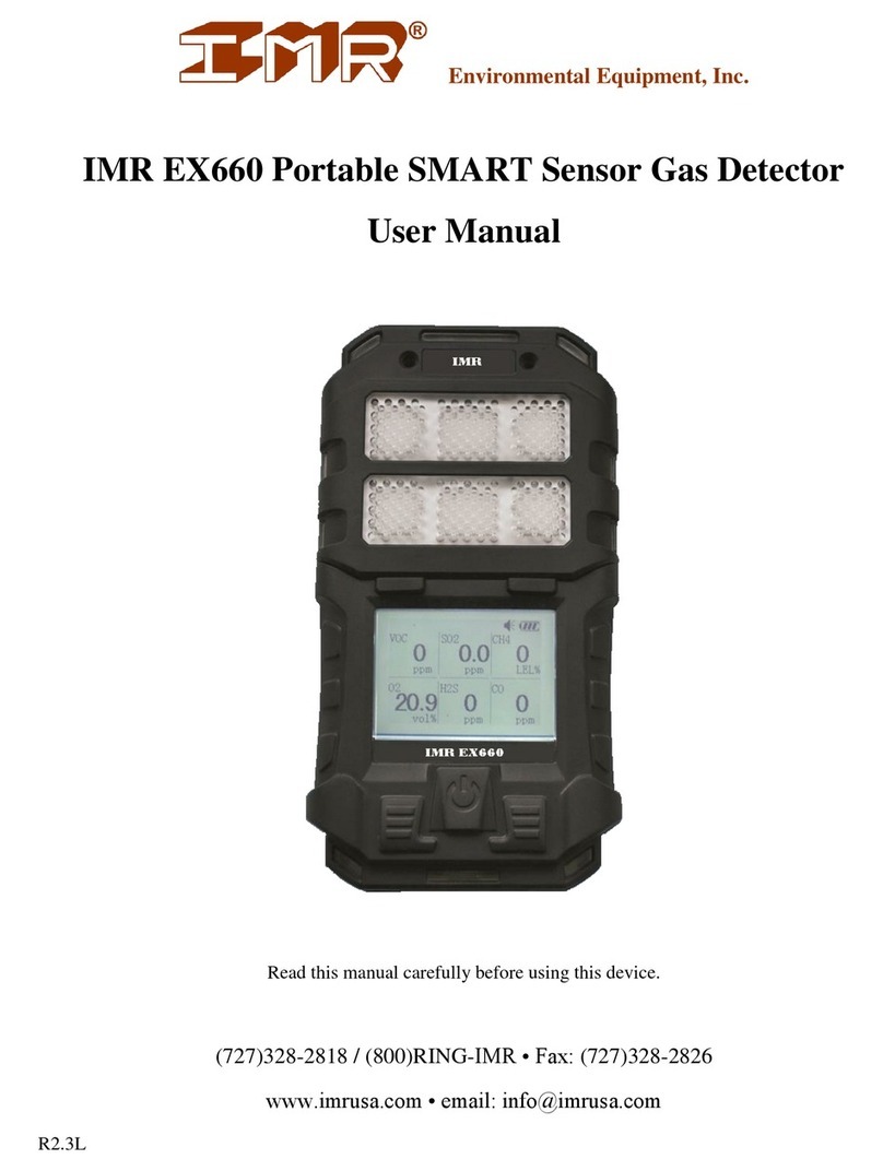
IMR EX660 User manual

Environmental Equipment, Inc. IMR EX660
Ver. 3.0A4
IMR EX660
Personal Multi-Gas Detector
User Manual

Environmental Equipment, Inc. IMR EX660
IMR EX660 Manual
3634 Central Ave. St. Petersburg, FL 33711 Phone: 727-328-2818 / 800-RING-IMR
www.imrusa.com Fax: 727-328-2826
THE PRIDE OF THE COMPANY –MADE IN THE USA Page 2of 14
CONTENTS
1. Safety and Usage Information .......................................................................................................3
2. Introduction....................................................................................................................................3
3. Main Features.................................................................................................................................4
4. Technical Specification..................................................................................................................4
5. Structure and Functions .................................................................................................................4
6. Operation Instructions....................................................................................................................5
6.1. Power On.................................................................................................................................5
6.2. Power Off................................................................................................................................5
6.3. Bump Test ...............................................................................................................................5
6.4. Menus......................................................................................................................................6
6.4.1. Settings Menu ..................................................................................................................6
6.4.2. Advanced Menu...............................................................................................................7
6.5. Gas Detection..........................................................................................................................8
6.6. Status Review..........................................................................................................................8
6.7. Auto Zero Calibration .............................................................................................................8
6.8. Calibration...............................................................................................................................8
6.8.1. Configuration Menu.........................................................................................................8
6.8.2. Zero Calibration...............................................................................................................9
6.8.3. Span Calibration...............................................................................................................9
6.9. Alarm Point...........................................................................................................................10
6.10. Sensor Channel..................................................................................................................11
6.11. Password............................................................................................................................11
7. Battery Charging..........................................................................................................................11
8. USB Communication (optional) ..................................................................................................11
9. Replacing Sensors........................................................................................................................11
10. Accessories ..................................................................................................................................12
11. Troubleshooting...........................................................................................................................12
12. Warranty ......................................................................................................................................13
13. Contact IMR.................................................................................................................................14

Environmental Equipment, Inc. IMR EX660
IMR EX660 Manual
3634 Central Ave. St. Petersburg, FL 33711 Phone: 727-328-2818 / 800-RING-IMR
www.imrusa.com Fax: 727-328-2826
THE PRIDE OF THE COMPANY –MADE IN THE USA Page 3of 14
1. SAFETY AND USAGE INFORMATION
Improper use or usage in an inappropriate environment may degrade the instruments performance.
Read the safety information below before using/operating this device.
Do not use a damaged device. Check for cracked or missing parts before use.
Before use it is advised that a “Bump Test” be performed. See section 6.3 for more information.
If the reading is out of range then the device should be calibrated. See section 6.7 and 6.8.
Periodic “Bump Tests” will allow for testing of the sensor response, visual, audible and vibrate
functions.
Do not use accessories that are not designed to be used with the EX660.
Only use the charger provided with the EX660. Do not charge the device in hazardous
environments.
Do not expose the device to high gas concentrations for an extended period. Doing so can harm
sensor performance and possibly damage them.
Do not use the device in environments that contain lead compounds, sulfate compounds, organic
phosphorus compounds, or silicon. These compounds can damage the sensor cells.
Avoid exposure to environments that contain H2S, Hydrocarbons or acidic gases for an extended
period. If the device has been used in these environments preform a “Bump Test” before its next
use. See section 6.3.
Avoid exposure to environments with the potential for electric shock, strong magnetic fields or
extreme continuous mechanical vibration.
Do not discard the lithium battery in the trash. Follow local regulatory requirements for disposal
of the battery.
Do no preform any unauthorized maintenance of the device.
Avoid dropping the device from heights and extreme impacts.
For usage information not included in this manual contact IMR.
2. INTRODUCTION
The EX660 is a compact and lightweight multi-gas detector that continuously measures combustibles
such as O2, CO, H2S and other toxic gases in ambient air. It can be equipped with up to 6 different
sensors. It has a rugged and watertight design (IP66). With an impact resistant rubberized case to
meet the toughest requirements of the harshest environments.

Environmental Equipment, Inc. IMR EX660
IMR EX660 Manual
3634 Central Ave. St. Petersburg, FL 33711 Phone: 727-328-2818 / 800-RING-IMR
www.imrusa.com Fax: 727-328-2826
THE PRIDE OF THE COMPANY –MADE IN THE USA Page 4of 14
3. MAIN FEATURES
Advanced 16 bit MCU with low noise
Ultra-wide angle LCD screen
Adjustable 2-level alarm
Automatic zero calibration
Self-protection for combustible gas sensor
Low battery alarm function
Real-time clock
Interchangeable smart sensor module
design
Audible, visual and vibrate alarms
Data export functionality
STEL/TWA alarm for toxic gases
Password management
Intrinsically safe design
4. TECHNICAL SPECIFICATION
Detection method: Natural diffusion
Target gas: See calibration certificate
Response time:
Semi-conductor, catalytic, thermal conduct sensors........T90<30s
Electrochemical sensors...................................................T90<30s
Other sensors....................................................................T90<120s
Indication error range:
Combustible gas...............................................................±5% F.S.
Toxic gas..........................................................................5ppm
Working condition:
Temperature: -20℃~50℃ .............................................Humidity: <95%RH
Power source: Lithium battery (DC3.6V, 6600mAh)
Working time per charging: ≤ 30 hours continuously (without alarms)
Charging time: ≤ 6 hours
Explosion –proof grade: Exia IIC T4 Ga
Ingress protection: IP66
Dimensions and weight: 168mm×91mm×45mm about 500g
5. STRUCTURE AND FUNCTIONS
Appearance
Display information

Environmental Equipment, Inc. IMR EX660
IMR EX660 Manual
3634 Central Ave. St. Petersburg, FL 33711 Phone: 727-328-2818 / 800-RING-IMR
www.imrusa.com Fax: 727-328-2826
THE PRIDE OF THE COMPANY –MADE IN THE USA Page 5of 14
6. OPERATION INSTRUCTIONS
6.1.POWER ON
When the device is powered off, hold
for more than 3s and it will power on. The
screen will display as below.
After powering on, the device will proceed to
self-test and the screen will display as below.
The device will then test the buzzer, alarm
lights and vibrator. After the self-test it will
enter into normal mode and the screen will
display as below.
Note:
If a self-test fails the relevant information
will be displayed. See section 11 for more
information.
If self-test succeeds the device enters into
a warm-up period of 3-30s which depends
on the sensor type.
6.2.POWER OFF
In normal mode hold for 3 seconds and
the screen will show “Shutting down…” and
the buzzer will give beep twice. Then device is
then powered off.
6.3.BUMP TEST
It is suggested that before each use to perform
a Bump Test to verify the device is working
normally.
Test method:
With the device powered on put it into a high
concentration gas environment. This area
should be higher than the preset high alarm
point. If all of the devices alarm functions
react then the device can be used normally.
Note:
If any reading is the expected error range
then see section 6.7 and 5.8 to recalibrate
the device.
If the device does not respond as expected
or displays errors then contact IMR.

Environmental Equipment, Inc. IMR EX660
IMR EX660 Manual
3634 Central Ave. St. Petersburg, FL 33711 Phone: 727-328-2818 / 800-RING-IMR
www.imrusa.com Fax: 727-328-2826
THE PRIDE OF THE COMPANY –MADE IN THE USA Page 6of 14
6.4.MENUS
6.4.1. Settings Menu
In normal mode press both and simultaneously and the device will enter into the settings
menu. Below is a list of menu items:
Menu
Submenu
Remarks
DATE TIME
When changing the date or time, the current
selection will blink.
ALARM MODE
When changing modes the current selection will
blink.
RECORD GAP
Set the time interval for measurement saving.
CAUTION MESSAGE
Black dot means this item is selected.
BATTERY MESSAGE
View battery voltage and remaining running time.
BACKLIGHT TIME
Backlight on time can be viewed and set in 5s
increments.
After entering into a submenu pressing changes the selected item value. Pressing will
save the setting. Pressing will exit without saving changes.

Environmental Equipment, Inc. IMR EX660
IMR EX660 Manual
3634 Central Ave. St. Petersburg, FL 33711 Phone: 727-328-2818 / 800-RING-IMR
www.imrusa.com Fax: 727-328-2826
THE PRIDE OF THE COMPANY –MADE IN THE USA Page 7of 14
6.4.2. Advanced Menu
When in the settings menu press both and simultaneously twice; the password prompt
will appear. Press to increase the value and press to confirm the input. If the password is
correct press to enter the advanced menu. Select a submenu by pressing . Then press
to enter the selected submenu.
Menu
Submenu
Remarks
SAFETY DEPLOY
Set users ID
ZERO CAL.
Set a new zero calibration
DATA UPLOAD
Upload saved data
PERIPHE ONFIG.
One mode must be selected
POWER MANAGE
Enable/disable extra functions
LANGUAGE SELECT
English or Mandarin
Note: the default password for the advanced menu is “0000”.

Environmental Equipment, Inc. IMR EX660
IMR EX660 Manual
3634 Central Ave. St. Petersburg, FL 33711 Phone: 727-328-2818 / 800-RING-IMR
www.imrusa.com Fax: 727-328-2826
THE PRIDE OF THE COMPANY –MADE IN THE USA Page 8of 14
6.5.GAS DETECTION
The device monitors and displays gas
concentration in real time. When a gas
concentration reaches the preset alarm point
the alarms will activate.
Note:
Do not block sensors when in use.
The use of filters will extend sensor life.
Extended non-use, extreme physical shot
or exceedingly high concentrations of gas
may cause the zero point to drift. If the
reading in clean are is not zero then a zero
calibration is needed. See section 7.7 and
7.8.
6.6.STATUS REVIEW
In normal mode press to change the
screen to show the current temperature, time,
STEL value①, TWA value①, maximum level
of gas②and minimum level of gas②since
power on.
Note:
①Only for toxic gas. ②Only for oxygen.
6.7.AUTO ZERO CALIBRATION
In normal mode hold both and for
about 1 second. The device prompt for the
password. After entering the correct password
the advanced menu will be displayed.
Select and press . The device
will perform zero calibration. When
completed a “√” is displayed for success and
“×” if failed.
6.8.CALIBRATION
WARNING!
Only qualified personnel should attempt
calibration. An improper calibration will
cause the device to not work properly
6.8.1. Configuration Menu
While the device is powered off hold
and simultaneously for about 3 seconds.
The device will then perform a self-test after a
short delay. Then the password screen will be
shown.
After the correct password is entered the
device will enter the configuration menu seen
below.
Press to change the current selection.
The current selection will be shown in black.
Press to enter a submenu.

Environmental Equipment, Inc. IMR EX660
IMR EX660 Manual
3634 Central Ave. St. Petersburg, FL 33711 Phone: 727-328-2818 / 800-RING-IMR
www.imrusa.com Fax: 727-328-2826
THE PRIDE OF THE COMPANY –MADE IN THE USA Page 9of 14
6.8.2. Zero Calibration
Select and press to enter the
auto zero calibration interface. As seen below.
When completed a “√” is displayed for
success and “×” if failed.
In zero calibration mode press and the
device enters the manual zero calibration
interface. As seen below.
When the AD value of the sensor is stable
press to save the new values zero
calibration. Then a “√” is displayed for
success and “×” if failed. As seen below.
6.8.3. Span Calibration
After zero calibration the device displays a
countdown. As seen below.
On the next screen enter the calibration gas
concentration. As seen below.
If the concentration needs to be changed press
to enter the screen below.
Press to change the selected digit and
press to change the value. After the last
value is entered press to save and
continue to applying the test gas. As seen
below.
→

Environmental Equipment, Inc. IMR EX660
IMR EX660 Manual
3634 Central Ave. St. Petersburg, FL 33711 Phone: 727-328-2818 / 800-RING-IMR
www.imrusa.com Fax: 727-328-2826
THE PRIDE OF THE COMPANY –MADE IN THE USA Page 10 of 14
Once the device senses the test gas the display
will update. As seen below.
If there is a need to do the calibration
manually press . The screen will update
and will now continue in manual calibration
mode.
Press again to confirm the manual
calibration. The below 2 images depict a
successful and failed manual calibration.
Once a sensors calibration is completed the
device will continue on to the next sensor until
all are calibrated. This operation follows as
noted in previous sections.
If a sensor does not need to be calibrated press
to skip that sensor.
6.9.ALARM POINT
Press to highlight and press
to enter the submenu. As seen below.
Press to change the selected digit then
press on the value that needs to be
changed. The next screen will allow for the
value to be modified. As shown below.
Press to change the selected digit then
press to change the value.
Press to save changes. The next alarm
point will then be displayed.
Note:
H - High alarm point
L - Low alarm point
ST - STEL alert point
TW - TWA alert point

Environmental Equipment, Inc. IMR EX660
IMR EX660 Manual
3634 Central Ave. St. Petersburg, FL 33711 Phone: 727-328-2818 / 800-RING-IMR
www.imrusa.com Fax: 727-328-2826
THE PRIDE OF THE COMPANY –MADE IN THE USA Page 11 of 14
6.10. SENSOR CHANNEL
Press to highlight and press
to enter the submenu. A seen below.
Press to change the selected sensor
location; the channel box will flash. Press
to enable or disable a channel. An
enabled channel has a black dot in the center.
Keep pressing until all the channels have
been set. The device will save the settings and
exit to normal mode. Closed channels will
have a displayed.
6.11. PASSWORD
Press to highlight and press
to enter the submenu. As seen below.
Press to change the selected digit then
press to change the value. Once
completed press to save the new
password.
CAUTION!
After setting the new password make note
of the new one!
7. BATTERY CHARGING
If a low battery alert is activated or the device
cannot be powered on charge the device
immediately in a non-hazardous area.
First ensure the device is powered off. Then
connect the charger to it. Lastly connect the
charging plug. The device will be power on
automatically and display a battery symbol on
the screen. The symbol will indicate the
charging status. When the symbol is all back
and not changing; charging is complete. The
A/C plug can now be disconnected and then
the device plug can be removed.
WARNING!
Do NOT charge the device in a
hazardous area.
The device cannot be used when
charging.
Avoid charging the device while it is
powered on as this will increase
charging time.
8. USB COMMUNICATION (OPTIONAL)
This function is only available for the device
which includes USB data cable.
Connect the USB data cable correctly between
the device and computer. Then run the EX660
software.
9. REPLACING SENSORS
The device uses smart sensor modules which
are suggested be calibrated every year.
If a sensor is no longer working contact IMR
for replacements.

Environmental Equipment, Inc. IMR EX660
IMR EX660 Manual
3634 Central Ave. St. Petersburg, FL 33711 Phone: 727-328-2818 / 800-RING-IMR
www.imrusa.com Fax: 727-328-2826
THE PRIDE OF THE COMPANY –MADE IN THE USA Page 12 of 14
10.ACCESSORIES
Hand ring
1 pc
Alligator clip
1 pc
Calibration cover
1 pc
Operation manual
1 copy
Charger
1 pc
How to use the clips and hand ring:
Belt clip, alligator clip and hand ring can be screwed to the back of the instrument when
necessary.
If belt clip is used more frequently then remove the alligator clip first and then install it on the
instrument.
11.TROUBLESHOOTING
Symptom
Problem
Solution
Not powering on
Low voltage
Charge it
Hardware damaged
Contact IMR
Circuit fault
Contact IMR
No response to gas
Warm-up not finished
Wait till it finishes
Circuit fault
Contact IMR
Gas reading not accurate
Sensor replacement overdue
Contact IMR
Sensor drift
Re-calibrate it
Time and date are wrong
Battery is fully discharged
Charge it and re-set the time
and date
Intense electromagnetic
interference
Reset the time and data
Zero calibration function is
unavailable
Too much sensor drift
Re-calibrate or replace the
sensor module
Displaying “-0” in normal
mode
Sensor drift
Make zero calibration

Environmental Equipment, Inc. IMR EX660
IMR EX660 Manual
3634 Central Ave. St. Petersburg, FL 33711 Phone: 727-328-2818 / 800-RING-IMR
www.imrusa.com Fax: 727-328-2826
THE PRIDE OF THE COMPANY –MADE IN THE USA Page 13 of 14
12.WARRANTY
IMR Environmental Equipment, Inc. states the following:
IMR‚ as manufacturer hereby grants the following worldwide IMR warranty for an IMR analyzer
purchased from an authorized dealer.
1. The IMR warranty shall entitle every IMR customer to demand a free replacement or repair of
the defective parts from any IMR dealer authorized for the respective IMR unit.
2. The IMR warranty shall be granted on the factory new unit and shall commence on the date of
the delivery of the original IMR unit to the customer.
3. The IMR warranty shall refer to absence of faults with respect to the state of the art nature of the
sold unit in terms of material and finish. The warranty for all parts fitted during the twelve-month
warranty period shall end with the unit warranty.
4. After the establishment of a material or production fault by IMR or the authorized IMR dealer,
the faults will be eliminated by means of free repair or replacement. Replaced parts shall become
the property of IMR.
5. No warranty claims may be made for maintenance and setting work, cleaning or other utility
materials required for the function of the unit and other wear parts unless they have a direct
bearing on work performed under the warranty.
6. The terms and conditions for the acknowledgement of this warranty shall be the presentation of
the fully completed warranty card, which must contain the confirmation from the authorized IMR
dealer on its delivery and, if applicable, the prescribed maintenance work.
7. The IMR warranty shall only be applicable if
7.1. The analyzer has been maintained in accordance with the instructions issued by the
manufacturers and the operating instructions by an authorized IMR dealer.
7.2. Only original IMR spare parts have been used for any repairs.
7.3. The unit has been used properly, the operating instructions observed and the unit has not
been used for a purpose other than the one for which it has been designed.
7.4. The IMR unit has been left in its original design and meets the original IMR specifications.
7.5. The fault is not due to external influences or use for a purpose other than the one for which it
has been designed.
7.6. Exclusively authorized IMR dealers have made repairs to the IMR unit.
7.7. The IMR unit has been sent to an authorized IMR dealer immediately after the fault was
discovered.
8. Warranty time for the analyzer, including electrochemical sensors is 12 months.

Environmental Equipment, Inc. IMR EX660
IMR EX660 Manual
3634 Central Ave. St. Petersburg, FL 33711 Phone: 727-328-2818 / 800-RING-IMR
www.imrusa.com Fax: 727-328-2826
THE PRIDE OF THE COMPANY –MADE IN THE USA Page 14 of 14
13.CONTACT IMR
IMR Environmental Equipment, Inc.
3634 Central Ave.
St. Petersburg, FL 33711
USA
Phone: 727/328-2818
Fax: 727/328-2826
1800#: 1-800/746-4467
Internet: www.imrusa.com
IMR® is a registered Trademark of IMR® Environmental Equipment, Inc.
Other manuals for EX660
2
Table of contents
Other IMR Gas Detector manuals
Popular Gas Detector manuals by other brands
RKI Instruments
RKI Instruments GasWatch 2 Operator's manual

Consilium
Consilium Salwico SW2020 user manual
Opera
Opera 6000 series Installation guidelines
Crowcon
Crowcon Xsafe Bright Installation, operation and maintenance instructions
RKI Instruments
RKI Instruments 61-1004RK Operator's manual
Honeywell
Honeywell Signalpoint Pro Technical manual
