NOTICE
The SPD unit’s performance will be degraded if the
conductors are (a) too long, (b) are of too small a wire
gauge, (c) have too many bends or (d) have sharp bends.
Les performances du SPD seront dégradées si les
conducteurs sont (a) trop longs, (b) d’un calibre de fil
trop faible, (c) présentent trop de courbures ou (d) ont
des courbures trop prononcées.
The factors listed above should be addressed during the
design of an installation to reserve a suitable place for
the OVRHTP series unit next to its point of connection
to the electrical system. The selected mounting location
should allow for the shortest possible conductor runs
and a direct route with a minimum of bends. If bends are
required, they should be sweeping bends. Do not make
sharp 90° bends for appearance purposes because
they will decrease the effectiveness of the OVRHTP
series unit.
Binding or twisting conductors together using cable
ties or electrical tape improves the protection
performance of the device.
—
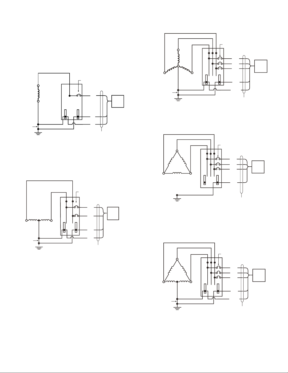
Conductors
—
Wiring color installation guide
Voltage (V) A, L1 B, L2 C, L1 Neutral Ground
Black White Green/yellow
Black White Green/yellow
Brown Blue Green/yellow
Brown Blue Green/yellow
Black White Green/yellow
Black White Green/yellow
Black White Green/yellow
Black White Green/yellow
Black Red White Green/yellow
Brown Orange White Green/yellow
Black Red Blue White Green/yellow
Black Brown Gray Blue Green/yellow
Black Brown Gray Blue Green/yellow
Brown Orange Yellow White Green/yellow
Brown Orange Yellow White Green/yellow
Black (A) Black (B) Black (C) White Green/yellow
Black Orange (HL) Blue White Green/yellow
Black Red Blue Green/yellow
Black Red Blue Green/yellow
Black Brown Gray Green/yellow
Brown Orange Yellow Green/yellow
Black (A) Black (B) Black (C) Green/yellow
Brown Blue Green/yellow
Brown Blue Green/yellow
Brown Blue Green/yellow
Brown Blue Green/yellow
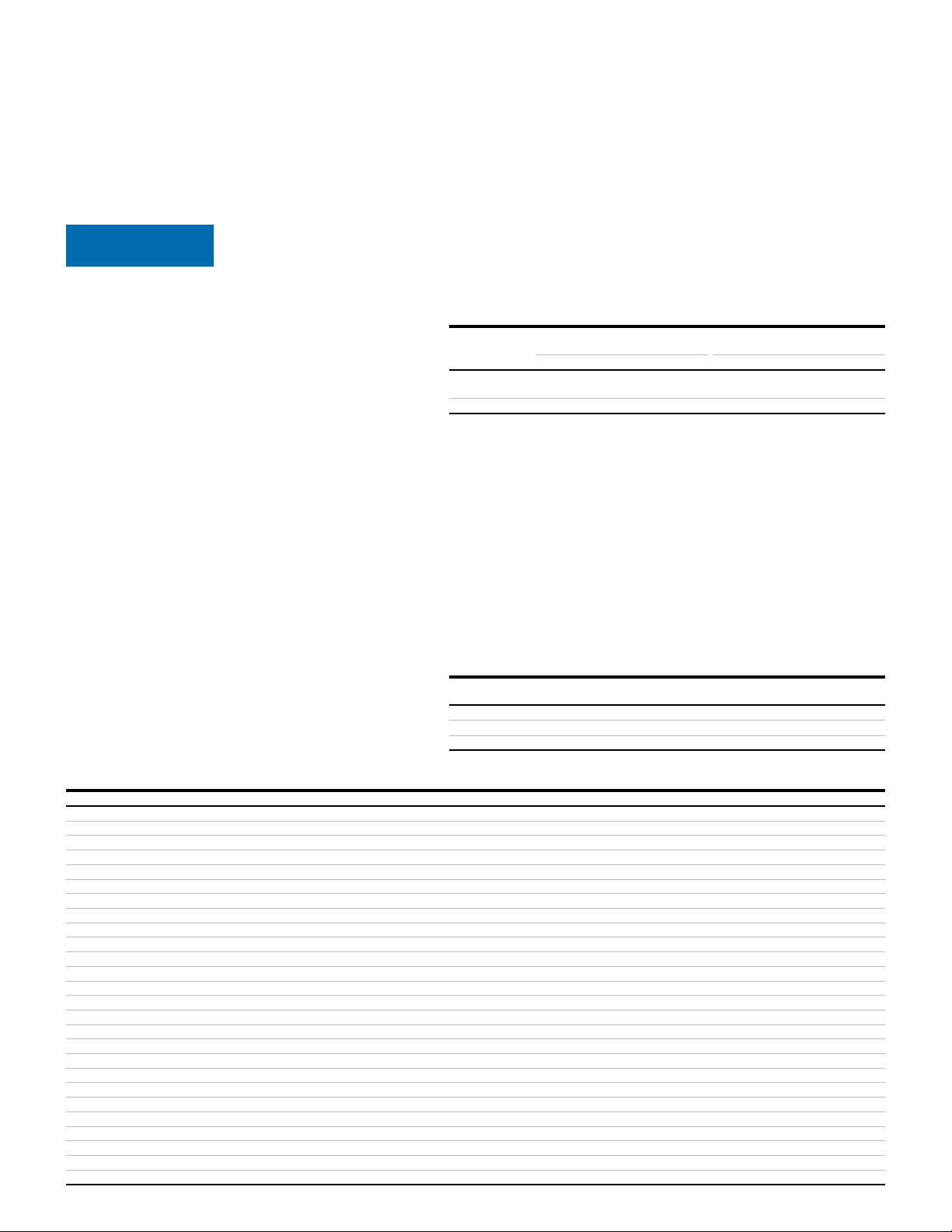
Upstream overcurrent protection device (OCPD)
The OVRHTP series units can either be Type 1 or Type 2. Please refer
to the SPD types chart to determine the SPD type for the unit.
—
SPD types
Country SPD
is installed in
Polycarbonate enclosure Metal and stainless steel enclosure
UL 1283 Not UL 1283 UL 1283 Not UL 1283
United States and
all other countries
Canada
The OVRHTP series unit is a one-port SPD and is to be connected in
parallel with the electrical system. It may be connected via a circuit
breaker, molded case switch, fused switch, or connected directly to
the bus of the panelboard or switchboard (local and national electric
codes take precedence). If direct bus connection is used, ABB
recommends installing the OVRHTP series unit behind a disconnect
switch or other disconnecting means for ease of serviceability.
If the unit is Type 2, the following OCPD is recommended:
Si l’unité est de type 2, il est recommandé d’utiliser le dispositif
suivant de protection contre les surintensités:
kA
United States and all other countries
États-Unis et tous les autres pays Canada
7SERVICE CONFIGURATIONS, CONDUCTORS