1. Available accessories
Mounting kits M1831-1 v3
• Mounting kits for space-saving mounting in racks,
cubicles or on walls
• IP54 protected mounting capability in cubicles for 670 and
650 series
RHGS cases SEMOD121070-2 v2
• RHGS 6, RHGS 12 and RHGS 30 cases enable mounting
of for example Combiflex modules
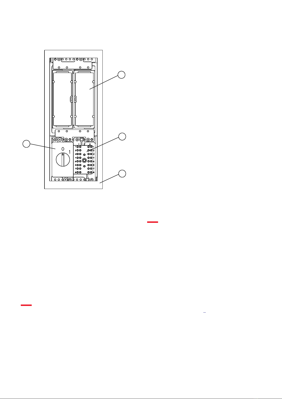
Test switch module M1947-1 v2
• Fail-safe testing of IEDs, using test switch RTXP 24
• Time saving while
– all connections for test are made from the front
– easy to move between IEDs of the same type
Combiflex modules SEMOD121075-2 v2
• Provide functionality such as lock-out, lock-out reset and
external contact re-enforcement
• Supervision
Key switch for settings M1990-1 v1
• Possibility to lock settings with key switch
Connectors M1997-1 v2
• Flexible connection of analog and binary signals
– Screw compression type
– Terminal blocks suitable for ring-lugs
External resistor unit SEMOD120184-10 v2
• Used with the High impedance differential protection
External current transformer unit SEMOD121078-2 v2
• Used for cost effective summation type differential
principle
Interface converter M1780-1 v2
• External interface converter from C37.94 to G703
• External interface converter from C37.94 to G703.E1
GPS antenna SEMOD121065-2 v2
• Used with the GPS time synchronization module GTM (or
GSM)
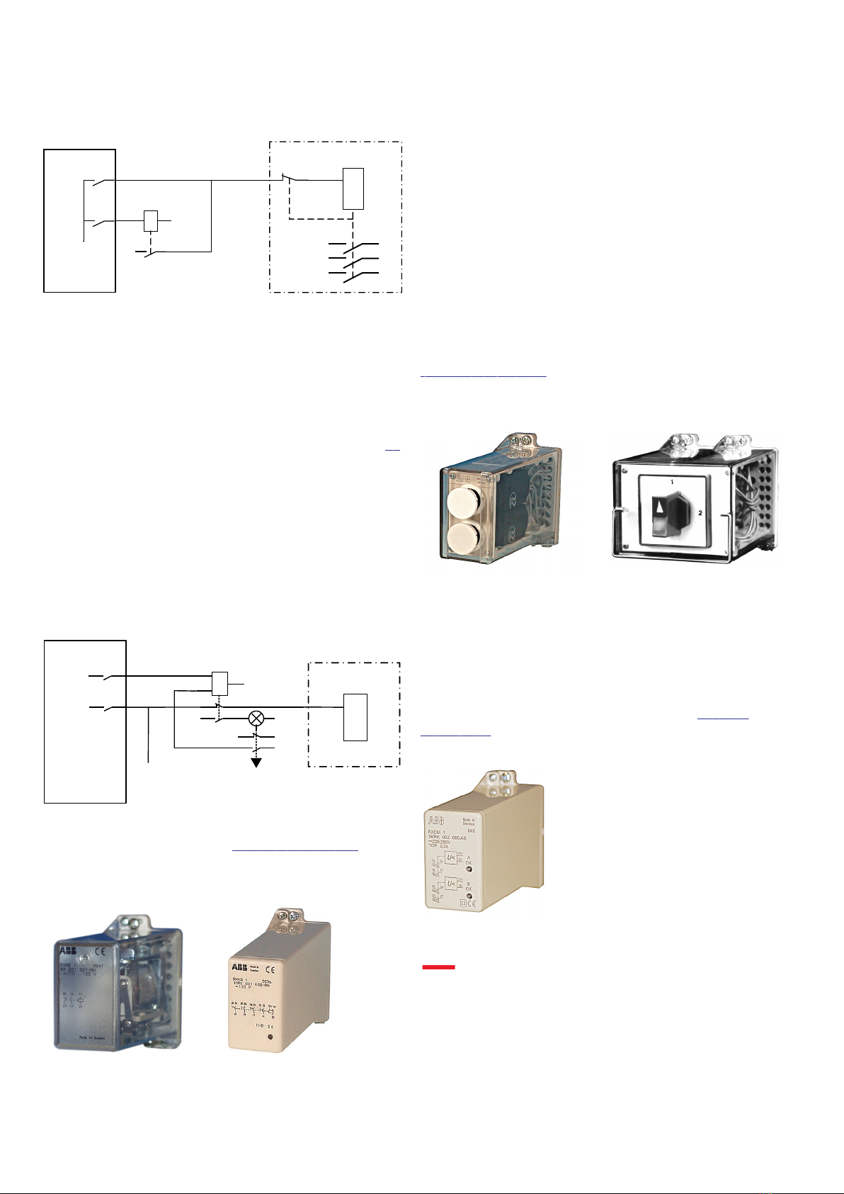
Injection equipment hardware REX060, REX061,
REX062 GUID-F6C11BE9-F5C7-4378-A3F0-9437B715E48A v1
• Is used to inject voltage and current signals to the
generator or motor.
COMBIFLEX Injection equipmentGUID-BFA755D6-9CE7-4342-B4F9-4E4F525A554A v2
RXTTE4 and optional protective resistor are used to inject
fundamental frequency AC voltage into the rotor circuit.
ESD Field Kit GUID-9C991E88-4B0E-4B1A-877A-F85E1ED192E1 v1
• Used to make work ESD safe
Power Supply GUID-2613CBA7-B7D0-4037-A3FA-01CB0DC14C40 v1
• Used to supply power to the IED
Configuration and monitoring tools SEMOD124331-1 v1M1890-1 v2
• Protection and control manager, PCM600, used to
– configure the IED
– set parameters
– monitor the IED and the system
– visualize and evaluate disturbance recordings M2078-1 v2
• Supervision and control of the power system via IEDs
(HV/Control package)
• Provides on request information from IEDs
• Collection of disturbances from IEDs
• Consists of standard library functions for easy application
engineering of a station HMI
Cable and dust cover GUID-17E99276-BE53-4D03-A6D8-B926C5F81F8F v1
• The cable is used to connect a PC to the RJ45 port on the
local human machine interface
• The dust cover protects the RJ45 port
Labels GUID-9F23A29B-E379-4705-A87F-3D9308354974 v1
• Used to label the LEDs
SAM600-IO LHMI service kit GUID-DA06ABEE-FAC7-4C7D-8912-A03FDDBEAA1D v2
• The SAM600-IO LHMI service kit is a support tool for
SAM600-IO during:
– Troubleshooting
– Commissioning
– Service
– Maintenance
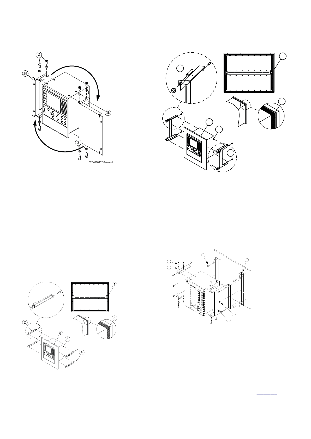
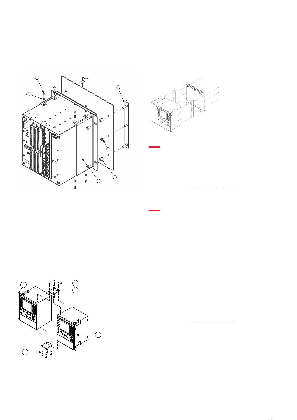
2. Mounting kits
19” rack mounting IP653-1 v1M1835-3 v3
Use the 19" rack mounting kit for 6U housing to mount the
IED in a standard rack. Combine the rack mounting kit with
the side-by-side mounting kit to mount IEDs or an IED and a
test switch module in the same rack position.
M1840-3 v2
The 19" rack mounting kit is available in four designs,
suitable for 1/4, 1/2, 3/4 or full width cases and consists of
two rack flanges (1a) and (1b) with appropriate mounting
details (2) for fastening to the case.
670/650 series and SAM600-IO IEC
1MRK 514 012-BEN K
Issued: June 2021
Revision: K
Hitachi Power Grids 6
© 2017 - 2021 Hitachi Power Grids. All rights reserved.