ABB TZIDC-210 User manual

—
ABB MEASUREMENT & ANALYTICS |
OPERATING INSTRUCTION | OI/TZIDC-210/TZIDC-220-EN REV. G
TZIDC
-210, TZIDC-220
Digital Positioner
—
ABB Measurement & Analytics
For your local ABB contact, visit:
www.abb.com/contacts
For more product information, visit:
www.abb.com/positioners
Digital Positioner
for the
positioning of pneumatically
controlled final control elements.
OI/TZIDC
-210/TZIDC-220-EN Rev. G 02.2023
—
TZIDC
-210
TZIDC
-220
Introduction
The
TZIDC-210, TZIDC-220 is an electronically
configurable positioner with communication
capabilities designed for mounting on pneumatic
linear or rotary actuators.
Fully automatic determination of the control
parameters and adaptation to the positioner
allow for
considerable time savings as well as
optimum control behavior.
Additional Information
Additional documentation on
TZIDC-210, TZIDC-220
is available for download free of charge at
www.abb.com/
positioners.
Alternatively simply scan this code:
—
We reserve the right to make technical changes or modify the contents of this
document without prior notice. With regard to purchase orders, the agreed particulars
shall prevail.
ABB does not accept any responsibility whatsoever for potential errors or po
ssible lack
of information in this document.
We reserve all rights in this document and in the subject matter and illustrations
contained therein. Any reproduction, disclosure to third parties or utilization of its
contents
– in whole or in parts – is forbidden without prior written consent of ABB.
© ABB 2023 3KXE341216R4201

2 TZIDC-210, TZIDC-220 DIGITAL POSITIONER | OI/TZIDC-210/TZIDC-220-EN REV. G
Table of contents
1Safety..........................................................................4
General information and instructions..................................4
Warnings....................................................................................4
Intended use .............................................................................4
Improper use.............................................................................4
Cable glands..............................................................................4
Warranty provisions.................................................................4
Cyber security disclaimer .......................................................5
Software downloads ...............................................................5
Manufacturer’s address..........................................................5
Service address.........................................................................5
2Use in potentially explosive atmospheres .............6
General requirements..............................................................6
Explosion protection approvals .......................................6
Standards applied...............................................................6
Product identification .............................................................6
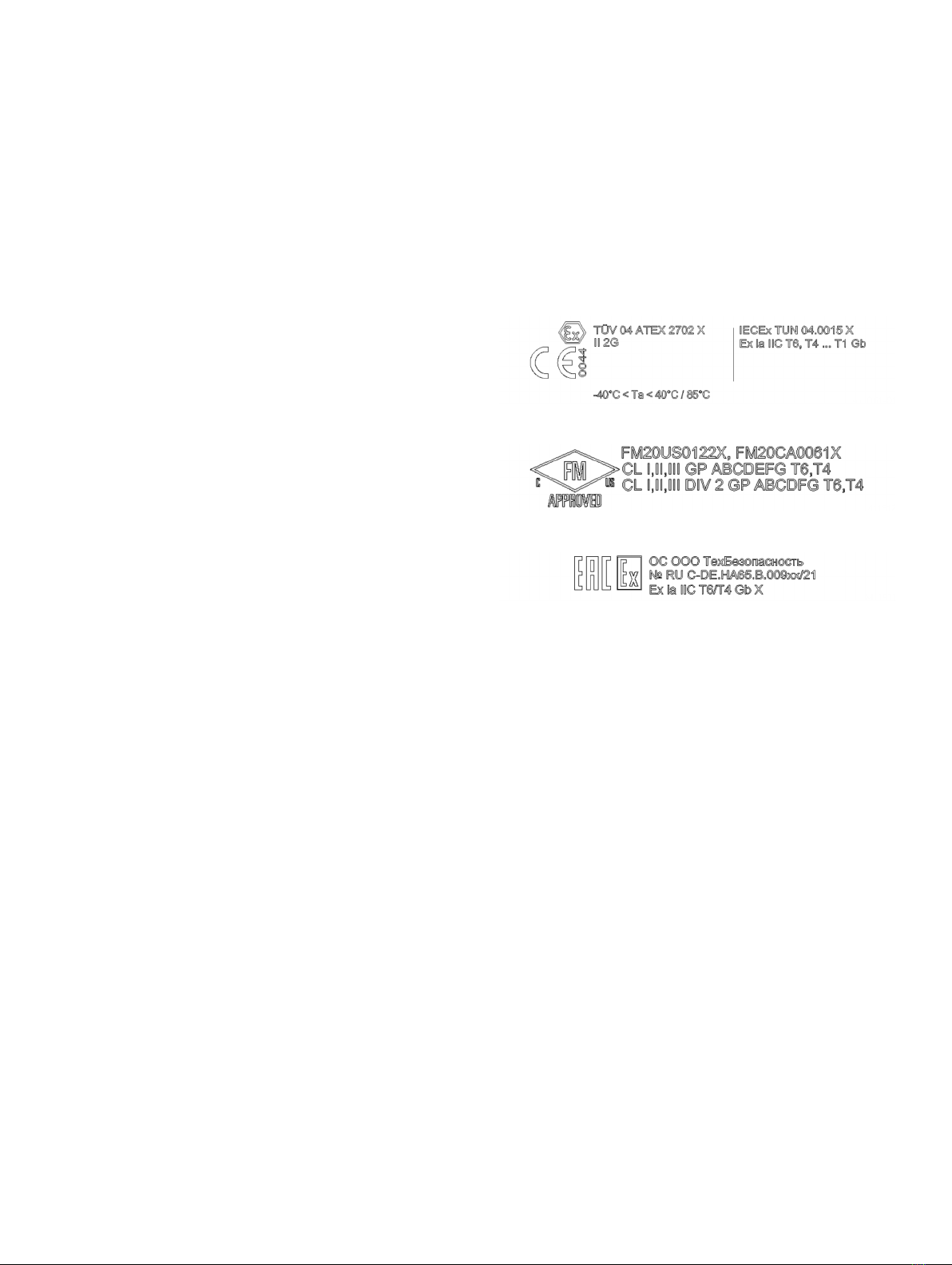
Marking (name plate) .........................................................6
Commissioning, Installation ..................................................7
Notes for operation ................................................................. 7
Use, Operation..........................................................................7
Maintenance, repair.................................................................8
Preconditions for safe operation of the positioner ..........9
Cable gland...........................................................................9
TZIDC-210 – Ex relevant specification ................................10
ATEX / UKEX – ‘Ex d’ type of protection .......................10
ATEX / UKEX – ‘Ex i’ type of protection......................... 11
IECEx – ‘Ex d’ type of protection..................................... 12
IECEx – ‘Ex i’ type of protection...................................... 13
cFMus ..................................................................................14
EAC TR-CU-012 Ex d ..........................................................18
EAC TR-CU-012 Ex i............................................................18
TZIDC-220 – Ex relevant specification................................20
ATEX / UKEX – ‘Ex d’ type of protection .......................20
ATEX / UKEX – ‘Ex i’ type of protection......................... 21
IECEx – ‘Ex d’ type of protection.....................................22
IECEx – ‘Ex i’ type of protection......................................23
cFMus ..................................................................................24
EAC TR-CU-012 Ex d ..........................................................28
EAC TR-CU-012 Ex i............................................................29
FM installation drawing No. 901265 .................................. 30
3Design and function ................................................35
Schematic diagram ............................................................... 35
Principle of operation ........................................................... 35
4Product identification............................................ 36
Name plate.............................................................................. 36
5Transport and storage ............................................37
Inspection ............................................................................... 37
Transporting the device ....................................................... 37
Storing the device.................................................................. 37
Ambient conditions.......................................................... 37
Returning devices .................................................................. 37
6Installation................................................................37
Safety instructions ................................................................ 37
Mechanical mounting............................................................ 38
General................................................................................ 38
Mounting on linear actuators ......................................... 39
Mounting on rotary actuator .......................................... 42
7Electrical connections ............................................ 43
Safety instructions ................................................................ 43
TZIDC-210, TZIDC-220 terminal assignment ....................44
Connections for inputs and outputs.............................44
Electrical data for inputs and outputs...............................45
Fieldbus input....................................................................45
Option modules ................................................................ 45
Connection on the device.....................................................46
Conductor cross-section................................................. 47
8Pneumatic Connections ......................................... 48
Safety instructions ................................................................48
Information on double acting actuators with spring-
return mechanism.............................................................48
Notes on ABB pressure gauge blocks ...........................48
Connection on the device.....................................................49
Air supply.................................................................................49

TZIDC-210, TZIDC-220 DIGITAL POSITIONER | OI/TZIDC-210/TZIDC-220-EN REV. G 3
9Commissioning........................................................50
Commissioning...................................................................... 50
Setting the bus address................................................... 51
Request information ............................................................. 51
Operating modes ................................................................... 51
Write protection and simulation mode..............................52
Standard automatic adjustment.........................................52
Standard automatic adjustment for linear actuators*
..............................................................................................52
Standard automatic adjustment for rotary actuators*
..............................................................................................52
Sample parameters................................................................53
Setting the mechanical position indication .................53
Setup of the feedback on the actuator position using
proximity switches........................................................... 54
Setup of the feedback on the actuator position using
microswitches................................................................... 54
10 Operation .................................................................55
Safety instructions.................................................................55
Parameterization of the device ...........................................55
Menu navigation................................................................55
Menu levels ..............................................................................56
Parameter overview...............................................................57
Parameter descriptions ...................................................58
11 Diagnosis / error messages ...................................60
Error codes............................................................................. 60
Alarm codes.............................................................................61
Message codes .......................................................................62
12 Maintenance.............................................................63
13 Repair........................................................................63
Safety instructions.................................................................63
Returning devices...................................................................63
14 Recycling and disposal............................................64
15 Additional documents ............................................64
16 Appendix...................................................................65
Return form .............................................................................65

TZIDC-210, TZIDC-220 DIGITAL POSITIONER | OI/TZIDC-210/TZIDC-220-EN REV. G4
1Safety
General information and instructions
These instructions are an important part of the product and
must be retained for future reference.
Installation, commissioning, and maintenance of the product
may only be performed by trained specialist personnel who have
been authorized by the plant operator accordingly. The specialist
personnel must have read and understood the manual and must
comply with its instructions.
For additional information or if specific problems occur that are
not discussed in these instructions, contact the manufacturer.
The content of these instructions is neither part of nor an
amendment to any previous or existing agreement, promise or
legal relationship.
Modifications and repairs to the product may only be performed
if expressly permitted by these instructions.
Information and symbols on the product must be observed.
These may not be removed and must be fully legible at all times.
The operating company must strictly observe the applicable
national regulations relating to the installation, function testing,
repair and maintenance of electrical products.
Warnings
The warnings in these instructions are structured as follows:
DANGER
The signal word ‘DANGER’ indicates an imminent danger.
Failure to observe this information will result in death or
severe injury.
WARNING
The signal word ‘WARNING’ indicates an imminent danger.
Failure to observe this information may result in death or
severe injury.
CAUTION
The signal word ‘CAUTION’ indicates an imminent danger.
Failure to observe this information may result in minor or
moderate injury.
NOTICE
The signal word
‘NOTICE’
indicates possible material damage.
Note
‘Note’ indicates useful or important information about the
product.
Intended use
Positioning of pneumatically controlled actuators; designed for
mounting on linear and rotary actuators.
The device is designed for use exclusively within the stated
values on the name plate and in the data sheet.
•The maximum operating temperature must not be exceeded.
•The maximum ambient temperature must not be exceeded.
•The housing's rating must be observed during operation.
Improper use
The following are considered to be instances of especially
improper use of the device:
•For use as a climbing aid, for example for mounting
purposes.
•For use as a bracket for external loads, for example as a
support for piping, etc.
•Material application, for example by painting over the
housing, name plate or welding/soldering on parts.
•Material removal, for example by spot drilling the
housing.
Cable glands
Cable glands should be selected and implemented by the
operator in accordance with their use and application
requirements.
The cable glands must comply with the requirements of
EN 60079-7, EN 60079-11 or EN 60079-15.
Especially in Ex applications, the requirements of the
appropriate type of protection should be observed.
Warranty provisions
Using the device in a manner that does not fall within the scope
of its intended use, disregarding this manual, using
underqualified personnel, or making unauthorized alterations
releases the manufacturer from liability for any resulting
damage. This renders the manufacturer's warranty null and void.

TZIDC-210, TZIDC-220 DIGITAL POSITIONER | OI/TZIDC-210/TZIDC-220-EN REV. G 5
Cyber security disclaimer
This product is designed to be connected to and to
communicate information and data via a network interface. It is
operator’s sole responsibility to provide and continuously ensure
a secure connection between the product and your network or
any other network (as the case may be).
Operator shall establish and maintain any appropriate measures
(such as but not limited to the installation of firewalls,
application of authentication measures, encryption of data,
installation of anti-virus programs, etc.) to protect the product,
the network, its system and the interface against any kind of
security breaches, unauthorized access, interference, intrusion,
leakage and/or theft of data or information.
ABB and its affiliates are not liable for damages and/or losses
related to such security breaches, any unauthorized access,
interference, intrusion, leakage and/or theft of data or
information.
Software downloads
By visiting the web pages indicated below, you will find
notifications about newly found software vulnerabilities and
options to download the latest software. It is recommended that
you visit this web pages regularly:
www.abb.com/cybersecurity
ABB Library – TZIDC-210 – Software downloads
ABB Library – TZIDC-220 – Software downloads
Manufacturer’s address
ABB AG
Measurement & Analytics
Schillerstr. 72
32425 Minden
Germany
Tel: +49 571 830-0
Fax: +49 571 830-1806
Service address
To find your local ABB contact visit:
www.abb.com/contacts
For more information visit:
www.abb.com/measurement
Other manuals for TZIDC-210
1
This manual suits for next models
1
Table of contents
Other ABB Industrial Equipment manuals

ABB
ABB ProKiln GAC400 User manual

ABB
ABB HT608707 User manual

ABB
ABB 630 series User manual

ABB
ABB AMG 0180 User manual

ABB
ABB Arc Guard System TVOC-2 Product manual

ABB
ABB HT600042 User manual

ABB
ABB HT613080 User manual

ABB
ABB HT564497 User manual

ABB
ABB SmartRack MV User manual

ABB
ABB HT845200 User manual