ABB SmartRack MV User manual

—
SmartRack™ MV
Remote racking device
—
INSTALLATION, OPERATIONS AND MAINTENANCE MANUAL
SmartRack™ MV
Remote racking device


—
Table of contents
04 Warranty and general information
05 Safety notices
06 Introduction
07 – 08 Receiving and storage
09 – 10 General description
11 Operation of device
16 Maintenance
17 Compatible devices
18 Specifications
19 – 20 Installation of SmartRack™ MV
adapter plate
21 PLC controller error codes
22 Renewal parts reference

4SMARTRACK™ MV REMOTE RACKING DEVICE
—
Warranty and general
information
Read the following hazard classifications carefully,
and fully inspect the equipment for any identifiable
hazards prior to installation, operation,
or maintenance. The following classifications listed
below will appear throughout this document
or on labels located on the equipment. These are
standard symbols defined by ANSI Z535.4-2011
which were established for recognition of potential
hazards which pose risk to life and property.
The classification is based on the probability
and severity of injury if the hazard is not avoided.
Please follow instructions, warnings, labels,
and codes for proper installation, operation,
and maintenance of equipment and devices. Only
Qualified Persons, as defined by NFPA 70, should
provide installation, operation, and maintenance
on this equipment and devices.
This is safety alert symbol. It is used to alert you
to potential physical injury hazards. Obey all safety
messages that follow this symbol to avoid possible
injury or death.
Danger: Indicates a hazardous situation which,
if not avoided, will result in death or serious injury.
Warning: Indicates a hazardous situation
that, if not avoided, could result in death
or serious injury.
Caution: Indicates that if the hazard is not avoided
could result in minor or moderate injury.
Notice: Is used to notify of practices not related
to personal injury.
Trademarks
Emax 2®
Emax 2 Ekip®
ReliaGear® LV SG
All third-party trademarks are the property of their
respective owners.
Warranty
This document is based on information available
at the time of publication. While efforts have been
made to ensure accuracy, the information
contained herein does not cover all details
or variations in hardware and software, nor does
it provide for every possible contingency
in connection with installation, operation,
and maintenance. Features may be described
herein that are not present in all hardware and
software systems.
ABB assumes no obligation of notice to holders
of this document with respect to changes
subsequently made. ABB makes no representation
or warranty, expressed, implied, or statutory, with
respect to, and assumes no responsibility for the
accuracy, completeness, sufficiency, or usefulness
of the information contained herein.
No warrantees of merchantability or fitness for
purpose shall apply. Contact your local sales office
if further information is required concerning any
aspect of ReliaGear LV SG switchgear and Emax 2
breaker operation or maintenance.
DANGER
WARNING
CAUTION
NOTICE
DANGER
WARNING
CAUTION
NOTICE
DANGER
WARNING
CAUTION
NOTICE
DANGER
WARNING
CAUTION
NOTICE
DANGER
WARNING
CAUTION
NOTICE

INSTALLATION, OPERATIONS AND MAINTENANCE MANUAL 5
Device specific
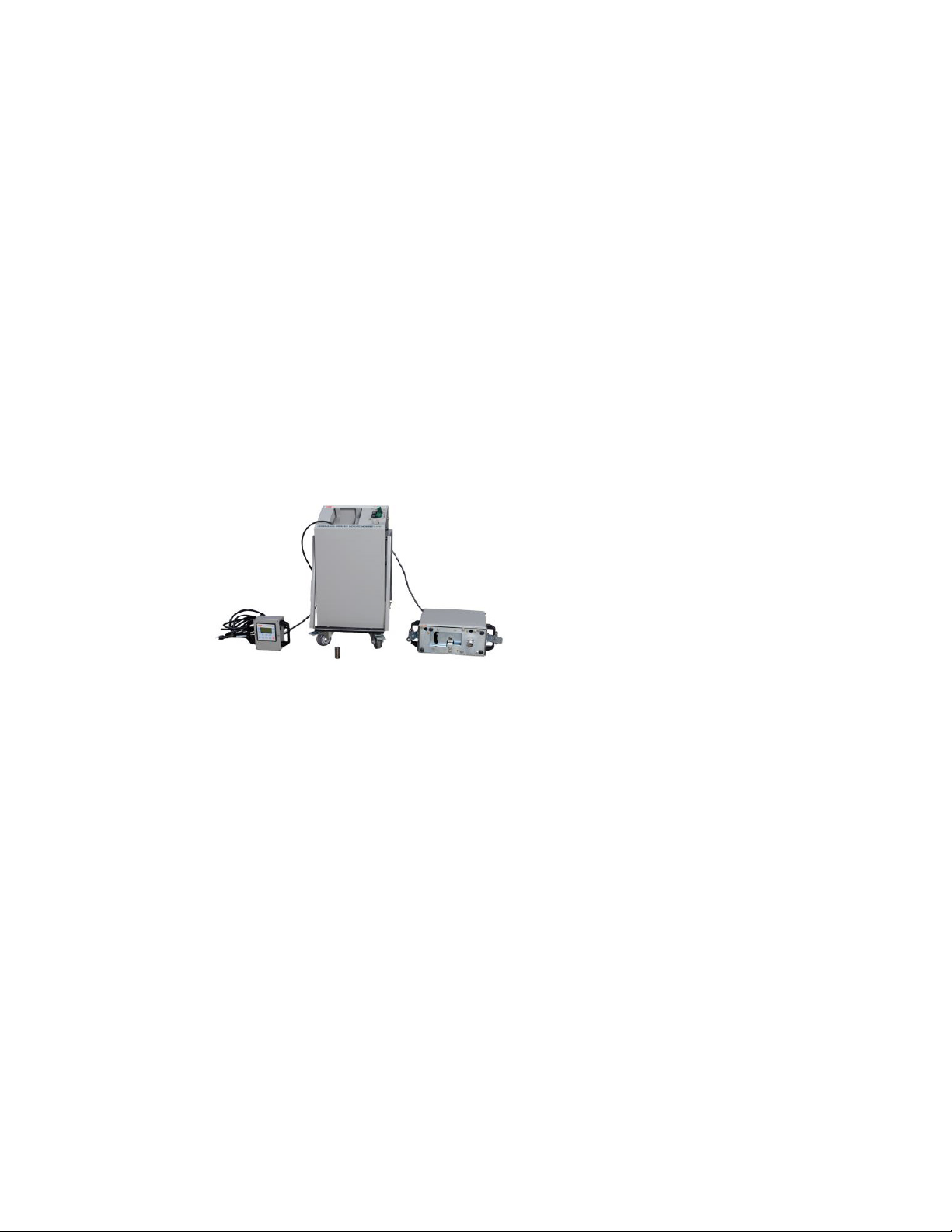
Warning: SmartRack™ MV remote
racking device incorporates
components, such as the DC power
supplies, which could contain stored
energy. Under no circumstances
should the protective covers on any
component of the device be removed.
Never tamper with, modify, or otherwise alter
the mechanical components, electronics, or control
software of the racking device. Failure to comply
could cause the device to fail resulting
in equipment damage or personal injury.
Never disconnect any of the cables from connected
components while the device is powered. Always
turn off the device and disconnect it from its power
source before attempting to unplug the data cables.
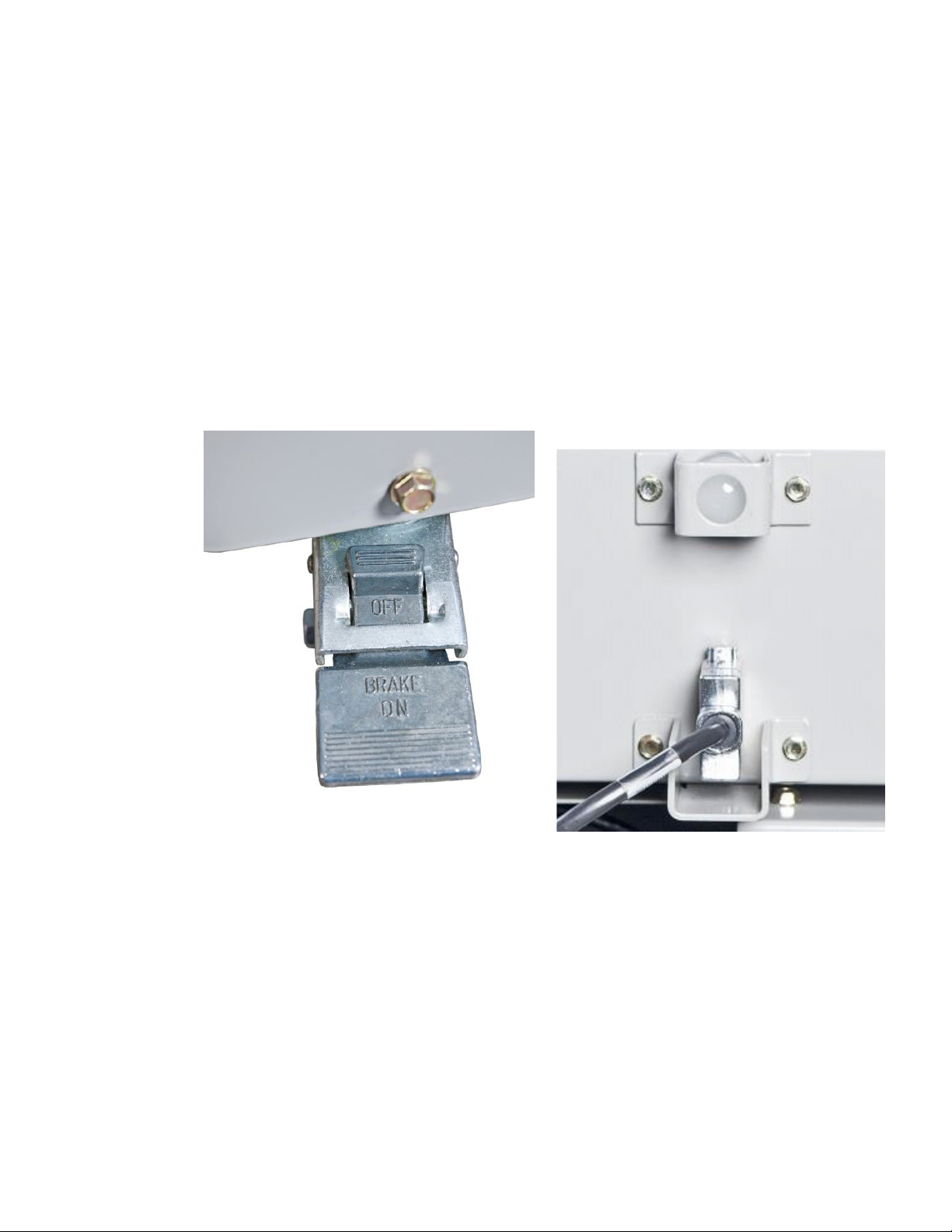
Do not open a cabinet door with SmartRack™ MV
attached. This could damage the racking device
coupling or circuit breaker truck. Always properly
remove the Motor Box using the rotary latch before
attempting to open the cabinet door.
SmartRack™ MV remote racking device is only
intended for use with switchgear breakers,
auxiliary devices such as PT or CPT drawout truck
and Model 2 MCC contactors listed in the
Compatible Devices section of this instruction
manual. ABB makes no claims to compatibility
regarding unlisted devices.
General
Always follow your company’s safety guidelines.
Wear appropriate Personal Protective
Equipment (PPE).
This product is intended to be operated and
maintained by qualified persons thoroughly trained
and knowledgeable of the hazards involved. This
publication is written only for such qualified
persons and is not intended to be a substitute for
adequate training and experience in the safety
procedures for this device.
Detailed descriptions of standard repair
procedures, safety principles, and service
operations are not fully elaborated in this
instruction book. It is important to note that this
document contains some warnings and cautions
against some specific service methods that could
cause personal injury to service personnel, or could
damage equipment or render it unsafe. These
warnings do not cover every conceivable method in
which service (whether or not recommended
by ABB) may be performed.
Secondly, ABB cannot predict or investigate all
potential hazards resulting from all conceivable
service methods. Anyone using service procedures
or tools, whether or not recommended by ABB, must
satisfy himself thoroughly that neither personal
safety nor equipment safety will be jeopardized by
the service method or tools selected.
All information contained in this manual is based
on the latest product information available at the
time of printing. ABB reserves the right to make
changes at any time without notice.
—
Safety notices
—
01
Personal Protective
Equipment
—
01
DANGER
WARNING
CAUTION
NOTICE

6SMARTRACK™ MV REMOTE RACKING DEVICE
Additional product support
For additional product support and details not
covered in the content of this instruction manual,
please contact your local sales representative.
The SmartRack™ MV remote racking device is able
to perform this complex task through the use of a
programmable logic controller and servomotor.
Throughout operation, the controller and motor are
in constant communication allowing the device to
accurately position a circuit breaker or other device
in the switchgear cell. The racking device
incorporates an actuator to operate the interlock
lever which eliminates need for an additional unit to
perform this task or for additional manual
interaction.
Overview
SmartRack™ MV remote racking device is intended
to assist technicians with the process of racking
medium voltage circuit breakers and associated
equipment. The main function of the device is to
perform the racking operation with minimal manual
interaction. This allows the operator of the device
to maintain a significant distance between
themselves and the circuit breaker while racking
is performed as compared to the traditional hand-
crank method of racking.circuit breaker while
racking is performed as compared to the
traditional hand-crank method of racking.
—
02
SmartRack™ MV
—
02
—
Introduction

INSTALLATION, OPERATIONS AND MAINTENANCE MANUAL 7
Receiving inspection
Upon receiving SmartRack™ MV, carefully unpack
the device from its box and check for the following
components which are fully furnished in the
assembled unit:
Should any parts be missing, please contact your
ABB sales representative.
Next, plug the device into an appropriate source
of power. See the Electrical Specifications section
for power requirements. With the device plugged
in, locate the On/Off switch on the top of the cart
and turn it to the On position. Both the green
indicator lights should illuminate. The lights show
incoming power to the device and the status of the
main power supply.
—
Receiving and storage
—
Table 1: Receiving inspection
—
03
On switch and
indicator lights
—
04
Start-up screen
—
03
Locate the Remote Control Box and make sure the
screen of the controller is properly displaying the
start-up screen as shown in Figure 5 below. If the
screen does not appear or does not look like Figure 5,
check all cable connections. If the start-up screen
does not appear after checking the connections,
do not use SmartRack™ MV and contact ABB
product support.
Handling the device
Plastic handles have been provided at multiple
places on the device to facilitate handling. These
should be used whenever possible to avoid
damage.
The cart includes a swinging push/pull bar with
plastic grip.
Component Quantity
Cart 1
Motor Box 1
Control Box 1
25 or 50ft. Connection Cable 2
Power Cable 1
Fuse 2
Socket Extension 1
—
04
SmartRack MV

8SMARTRACK™ MV REMOTE RACKING DEVICE
The Control Box incorporates two plastic handles
for lifting and for use while operating the device.
The control housing should never be picked up or
held by the cord.
The Motor Box has three plastic handles that are
located on either side and one in the rear to assist
the operator in the installation and removal of the
motor box to the mounting adapter plate. The
Motor Box should never be lifted by the protruding
hex socket or by the cord.
Storing the device
SmartRack™ MV must be stored indoors in a cool,
dry, dust-free place away from sunlight. During
periods of non-use SmartRack™ MV should be
covered to protect from accumulation of dust and
keep sunlight off the controller screen. The device
should be stored in an environment that meets the
temperature and humidity specifications shown in
Section Environmental Specifications.
SmartRack™ MV cart is intended to store and
transport all the components of the device. It is
good practice to always return the power, control,
and motor cables to their respective sections of
the cart, replace the Control Box to its spot, and
latch the Motor Box to the provided bracket.
—
05
Cart handle
—
06
Control box handles
—
07
Motor box handles
—
08
Properly stored
SmartRack™ MV
—
05
—
07
—
08
—
06

INSTALLATION, OPERATIONS AND MAINTENANCE MANUAL 9
Using the cart
Upon arrival, motor box, and control box will be
secured to the cart. All wiring and cables will be
inside of the cart.
The cart brakes need to be locked whenever the
cart is to be parked. Move the cart by disengaging
the brakes, lifting the handle, and pulling the cart.
Apply the brakes located behind the back wheels.
Connect the power cable, turn the power switch on,
and then follow the prompts on the control box.
After using the device, return the motor box and
control box to the original locations and replace the
cables to their original position within the cart.
Be sure to store the cart in a safe place and engage
the brakes when parking the cart.
Motor box
The motor box has a motor, gearhead, coupling,
and interlock actuator inside. The box is secured on
the door and cart using the rotary latches on the
sides of the motor box. There is one connector on
the back of the box, which is connected to the
actuator and the motor. There is also a three-color
indicator light on the back of the box, indicating an
idle state (green), the device in operation (yellow),
or an error (red).
The motor box has a socket protruding from the
motor, which connects to the end of the racking
screw. The socket can be removed and replaced
if required.
—
General description
—
09
Wheels and brake lever
—
10
Indicator light
and connector
—
09
—
10

10 SMARTRACK™ MV REMOTE RACKING DEVICE
The motor box has three handles to lift and
position the box. The operator should not use any
other method to mount the motor operator on the
mounting plate.
Control box
The control box consists of aluminum housing with
two handles on the sides, one handle on the rear
and a connector on the back, enclosing a pre-
programmed PLC/HMI controller. The controller is
connected to the cart by a standard length 25 foot
cable, allowing the operator to move to a safe
distance before operating SmartRack™ MV.
The controller will give instructions and feedback
to the operator throughout the process.
Optional equipment
Cable extension
SmartRack™ MV can be equipped with a 25 foot
long optional extension cable (2RGA015184A0001)
connecting the standard controller cable to the
controller. This provides additional distance
between the operator and the racking operation as
well as providing an extra measure of safety.
63kA socket
If racking 63kA switchgear, or if a custom door has
been installed on the switchgear, the additional
socket provided can be pinned to the drive. Remove
the standard socket by removing the screw, replace
the standard socket with the socket extension, and
use the same screw to secure the longer socket in
the hole on the drive closest to the face of the
motor box. The 63kA socket is a 16mm with a 3/8
drive and is 2 ¼ inches long.
ReliaGear ND socket
If racking ReliaGear ND switchgear, or if a custom
door has been installed on the switchgear, the
additional socket adapter provided can be attached
to the drive. The ReliaGear ND adapter is
approximately 4 inches long with a hex head on one
side and a square drive on the other. To install, insert
the socket adapter into the racking tube of the
switchgear and align it with the racking screw of the
breaker. The adapter is properly engaged when you
can push the adapter and depress the racking
interlock on the breaker truck. The adapter should
return to its initial position when you remove
pressure. Proceed with the installation process of the
motor box in the Operation of device/Set-up section.
—
11
Racking socket on
motor box
—
12
Control box
—
13a
Racking extended
socket for 63kA
13b
Extension socket
for ReliGear ND
—
11
—
12
—
13a
—
13b

INSTALLATION, OPERATIONS AND MAINTENANCE MANUAL 11
Read through the product warning (Figure 16) and
if acceptable press enter to continue. Otherwise,
turn off the device. Continuing from the warning
screen will bring up the install/ information
selection screen (Figure 17).
Inspection prior to use
Prior to using SmartRack™ MV, always inspect the
device for damage or wear. Ensure that all the cable
jackets are intact and all connectors are properly
secured. Do not use the device if any component is
damaged. Check for loose hardware, especially on
the Motor Box.
On the cell door, verify that the mounting adapter
plate for attaching the Motor Box to the door is
secure and the alignment pins are not bent.
Confirm the area is clear and follow all procedures
for working in the vicinity of power equipment
including wearing the appropriate PPE.
Setup
Wheel SmartRack™ MV up to the area where
racking is to be performed. The swivel wheels on
the side of the cart with the handle have locks
which should be engaged to keep the cart
in position.
Locate an appropriate power source and plug in the
power cord. Turn on the device using the switch and
verify both green lights are illuminated. Switching
on the device will power up the controller and it will
run through a startup procedure (Figures 15 and 16).
—
Operation of device
—
14
Controller start-up
screen
—
15
Product warning screen
—
16
Info/Install
selection screen
—
14
—
16
—
15
SmartRack MV
SmartRack MV
SmartRack MV

12 SMARTRACK™ MV REMOTE RACKING DEVICE
5.3 Motor box installation
When “Install Motor Box” is selected and “enter” is
pressed, the motor begins to rotate slightly back
and forth to assist in the mating of the 16mm
socket and the racking screw on the breaker, PT,
CPT, contactor or G&T truck. This slight rotation will
continue for 30 seconds or until the motor box
socket has engaged the racking screw. If the motor
box socket did not properly install, press enter to
restart the slight rotation.
After the Motor Box is secured to the mounting
plate on the door by rotating the two side latches,
the operator should take the hand-held Remote
Control Box and move a distance away as defined
by local procedure. Once the motor box is installed,
press enter to continue.
The Breaker, Auxiliary Unit, and MCC contactor
selection screens (Figure 22) operate the same. Use
the up and down arrows to highlight the correct
unit and press enter. The unit type can be changed
later from the main menu (Figure 23).
—
Figure 17
Installation process
started screen
—
Figure 18a
installation of motor
box 1
—
Figure 18b
Installation of motor
box 2
—
Figure 19
Motor box installed
screen
—
17
—
18b
—
19
—
18a
SmartRack MV
SmartRack MV

INSTALLATION, OPERATIONS AND MAINTENANCE MANUAL 13
Automatic racking
Automatic Racking is the device’s standard
operating mode. It allows the operator to specify a
starting position and an end position. The device
processes this information and then performs the
complete racking procedure.
Once Automatic Racking has been selected, the
select initial position screen (Figure 24) will request
the current position. Connect is when the unit is all
the way forward into the frame and both primary
and secondary connections are made. Disconnect
is when the unit is all the way backward where
neither the primary nor secondary connections are
made. Test is between disconnect and connect
where only the secondary connections are made.
Connect, Test, and Disconnect may be selected by
pressing function buttons F1, F2, and F3,
respectively. The ReliaGear ND platform will only
have Disconnect and Connect positions for the
circuit breaker.
Note that the Test option may not be available for
some devices, like potential transformers which
have no test position on the racking screw.
Once a start position has been selected, the text
for that position will be highlighted. Confirm the
selection by pressing the ENTER button. Always be
sure to double check the entered initial position
matches the actual position of the unit.
In the main menu screen, (Figure 23) the operator
can select either F1 for automatic racking, F2 to
change the unit type or F3 for manual racking.
Automatic racking should be used whenever
possible since it is intended to move devices
between positions. Manual Racking gives the user
greater control over the operation of the racking
device; however, should only be used in exceptional
circumstances, such as when a breaker failed to
completely rack to a position. Refer to Section
Automatic Racking or Section Manual Racking for
more detail on the racking process.
—
20
Unit type
selection screen
—
21
Main menu screen
—
22
Select initial
position screen
—
20
—
21
—
22
SmartRack MV
SmartRack MV
SmartRack MV

14 SMARTRACK™ MV REMOTE RACKING DEVICE
Once an initial position has been entered, the
device will display a screen to select the final
position (Figure 25). Note that some options, like
the selected initial position, will be unavailable.
Similar to the previous menu, the final end position
will be highlighted and must be confirmed by
pressing enter.
At this point SmartRack™ MV is ready to start the
Automatic Racking sequence. The program tells the
motor to torque to one side and then the other side
and then moves to the center of the hole as a
calibration of the breaker or other unit. If the unit is not
in a positive position such as Disconnect, Test, or
Connect, then SmartRack™ MV will not be able to
calibrate and a centering error will be displayed. Please
remove the motor and ensure that the unit is in a
positive position with the position interlock in place.
After initialization, the position interlock is
actuated. The operator can begin by pressing the
GO button. The operator can monitor racking
progress through the Automatic Racking screen
(Figure 26). The Automatic Racking screen displays the
device status and shows the relative position of the
unit inside the cell using an incremental status bar.
When SmartRack™ MV reaches 90% of its
calculated travel (i.e. from connect to test), the
position interlock is released. As the final 10% of
travel is completed, the position interlock should
make an audible click as it locks into the position.
Once SmartRack™ MV completes an automatic
position move, a racking complete screen (Figure 27)
appears showing the new current position of the unit.
Press the F1 button to move to a new position, or
BACK to return to the main menu.
Notice: After operating SmartRack™
MV in an automatic or manual move of
contactor, verify that the unit is in the
desired position visually or manually
through use of a racking handle before
operating unit.
Manual racking
Manual racking allows the operator greater control
over the unit as compared to Automatic Racking.
Rather than the device performing all the steps in the
racking process, the operator is responsible for
starting and stopping the unit being racked.
—
23
Select final
position menu
—
24
auto racking screen
—
25
racking complete screen
—
23
—
24
—
25
SmartRack MV
SmartRack MV
SmartRack MV
DANGER
WARNING
CAUTION
NOTICE

INSTALLATION, OPERATIONS AND MAINTENANCE MANUAL 15
Manual racking is not unit-specific. Initial and final
positions are not required for operation, although
other settings such as torque limit, velocity and the
existence of an interlock are unit specific; therefore,
considerable caution is required when using
SmartRack™ MV in manual mode.
If selected from the Main Menu, the racking device
goes directly to the Manual Racking screen (Figure 28)
and applies power to the Motor Box.
Once the Motor Box is secured to the cell door, the
operator should take the hand-held Control Box and
move a distance away as defined by their local
procedures. At this point SmartRack™ MV is ready to
start Manual Racking. This setting utilizes the three
buttons to the lower left of the screen (Figure 29).
The IN button moves the unit towards the contacts and
the OUT button moves the unit towards the door. These
buttons must be pushed and held to produce motion.
Releasing the button will cause the unit to come to a
stop. The button with a picture of a pad lock toggles the
interlock. In an emergency situation, the red STOP
button can be pressed to send a stop command to the
servomotor and cut power to the Motor Box.
Indicator lights
While SmartRack™ MV is in operation, the indicator
light on the motor box will change from green to
yellow. When racking is complete the indicator light
will return to green. The indicator color significance is
listed in table 2.
Racking complete
When either Automatic or Manual Racking is complete,
press the BACK button to return to the main menu. From
here racking can be repeated using the process explained
earlier in this section. Otherwise, return the hand-held
control to its place on the cart and detach the Motor Box
from the door by twisting the rotary latches on both
sides. Return the Motor Box to its area on the cart and
follow the instructions in Section Storing the Device.
Always ensure that the unit is completely racked to
the desired position and that the interlock pin has
dropped into its slot in the racking screw, if applicable,
before continuing.
—
26
Manual racking screen
—
27
Manual racking buttons
—
28
Motor box green, yellow
and red indicator lights
—
26 —
28
—
27
Condition Significance
Green Device ready
Yellow
Warning – Racking or interlock movement in
progress. All personnel should remain a safe distance
from SmartRack™ MV while in operation
Red Alert – Error encountered (flickers on startup)
Off No power to Motor Box
—
Table 2: Condition indicator lights
SmartRack MV

16 SMARTRACK™ MV REMOTE RACKING DEVICE
If there is a problem in the setup of the device or
while the device is operating, an error code will
appear on the screen. A list of the error codes and
the instructions of how to address each error is
available in Section PLC controller error codes.
Standard maintenance
No regular maintenance should be required, but
visual inspection prior to use is required. Possible
places for wear include, but are not limited to, the
socket head, the drive, the coupling, the gearhead,
and the actuator. All parts have been tested to 500
operations, but improper use of SmartRack™ MV
could cause failure.
Running the device in manual mode and listening
for irregular noise, such as a screeching, grinding,
or clunking sounds is not normal particularly if
SmartRack™ MV is giving error messages.
Before operating SmartRack™ MV, a visual
inspection must be conducted prior to use for
general problems.
Troubleshooting
—
29
Fuse installation
—
29
—
Maintenance
Problem Solution
No indicator lights illuminate
when the device is switched on.
If neither light turns on then
there is an issue with the
power source or fuse.
Only one indicator light
illuminates when the device
is switched on.
One light signifies that there
is an issue with the main
24VDC power supply.
—
Table 3: Troubleshooting

INSTALLATION, OPERATIONS AND MAINTENANCE MANUAL 17
—
Compatible devices
Indoor circuit breakers
• 63 KA 1200A ADVAC
• 63 KA 2000A ADVAC
• 63 KA 3000A ADVAC
• 50 KA 1200A AMVAC/ADVAC
• 50 KA 2000A AMVAC/ADVAC
• 50 KA 3000A AMVAC/ADVAC
• 40 KA 1200A AMVAC/ADVAC
• 40 KA 2000A AMVAC/ADVAC
• 40 KA 3000A AMVAC/ADVAC
• 31.5 KA 1200A AMVAC/ADVAC
• 31.5 KA 2000A AMVAC/ADVAC
• 31.5 KA 3000A AMVAC/ADVAC
• 25 KA 1200A AMVAC/ADVAC
• 25 KA 2000A AMVAC/ADVAC
• 25 KA 3000A AMVAC/ADVAC
• 25 kA 1200 A Vmax/A
• 25 kA 2000 A Vmax/A
• 31.5 kA 1200 A Vmax/A
• 31.5 kA 2000 A Vmax/A
• 7.2 Auxiliary Units
• PT in Advance Compartment
• CPT/ CPT Fuse Unit in Advance Compartment
• PT in SafeGear Compartment
• CPT/ CPT Fuse Unit in SafeGear Compartment
• 1200/2000A Manual and Electric G&T’s for
Advance/SafeGear
• 3000A Manual and Electric G&T’s for Advance/
SafeGear
• 1200 A Manual G&T for ReliaGear ND
• 2000 A Manual G&T for ReliaGear ND
• 7.3 MCC Contactors
• Model 2 MCC Contactor

18 SMARTRACK™ MV REMOTE RACKING DEVICE
—
Specifications
Parameter Value
Mechanical Life 500 Operations
Ambient Temperature Range 0°C to +40 °C
Continuous Output Torque 35 ft-lbs
Racking time from
Disconnect to Connect <120 seconds
Weight 25-50 lbs
Power Cable Length 25 feet
Control Cable Length 25 feet
Power Cable Size 10 gauge
Parameter Value
Input Voltage 120 VAC
Rated Current <20 Amps
Environmental
This is indoor equipment and is designed to operate
under standard service conditions as defined in ANSI
C37.04 for breakers and C37.20.2 for the switchgear
assembly washer that need to be removed from the
center of the lever itself. Then there are two screws
that hold the position release stop onto the door. Both
the position release stop and position release lever
need to be removed and discarded.
—
Table 4: Mechanical
—
Table 5: Electrical

INSTALLATION, OPERATIONS AND MAINTENANCE MANUAL 19
Doors with release lever
(advance and SafeGear)
Breaker doors have a position release lever
assembly on the front of the door (Figures 32 & 33).
This lever actuates by lifting the racking pin in the
withdrawable truck to allow the racking screw to
rotate. The mounting hardware that mounts this
lever in place can be used to also mount
SmartRack™ MV mounting adapter plate. The
exploded view (Figure 33) should be used as a
reference for disassembly and for reassembly of
these parts.
First, the position release lever should be removed
from the switchgear door (Figure 34). There is one
screw, a flat washer and a lock washer that need to
be removed from the center of the lever itself. Then
there are two screws that hold the position release
stop onto the door. Both the position release stop
and position release lever need to be removed and
discarded.
—
Installation of SmartRack™ MV
mounting adapter plate
—
30
Position release lever
—
31
Position release lever
exploded view
—
32
Removal of the
position release lever
—
33
Installation of
SmartRack™ MV
mounting adapter
plate
—
30
—
31
—
32
—
33

20 SMARTRACK™ MV REMOTE RACKING DEVICE
With SmartRack™ MV mounting adapter plate
mounted, re-assemble the spring onto the
replacement position release lever, and then the
latch into the housing (Figure 36).
With the latch rotated with torque against the spring,
align the position release lever as shown in Figure 36.
Use the same hardware that was removed (¼-20 x
3/8 screws) to install the position release lever.
Using the mounting adapter plate as a drilling
guide, drill a 9/32 inch hole through the square
holes on either side of the mounting plate through
the door. Install the ¼-20 X ¾ long carriage bolts
into these holes and secure with the flat & lock
washers plus the nut. These fasteners are required
to securely hold the mounting plate against the
door during racking.
Doors for ReliaGear ND
Locate and remove the two carriage bolts (1/4-
20X3/4), flat washers, lock washers, and hex nuts
on the front door where SmartRack adapter plate
will mount. Retain for future use.
Remove the three #10-24 carriage bolts, spacers,
washers, and hex nuts used to secure the racking
hole blocking plates and retain for future use.
Remove the bushing retaining ring and slide the
centering bushing out from the door. These will be
re-used as well.
To install the adapter plate, align the plate with the
two holes on the door and secure using the
¼-20X3/4 bolts that were removed previously.
Insert the centering bushing and secure it using the
bushing retaining ring that was removed previously.
Attach the blocking plates using the three #10-24
bolts that were removed previously.
Using the same hardware from the removal of the
position release stop, mount SmartRack™ MV
mounting plate to the Switchgear door with the
replacement position release lever (Figure 35) found in
the mounting adapter plate hardware bag. The longer
of the two screws should be screwed into the right hand
side. The end of this screw will be used to catch the end
of the spring.
—
34
Installation of posi-
tion release lever
—
35
Lever spring inside door
—
36
ReliaGear ND
adapter plate
—
34
—
36
—
35
Table of contents
Other ABB Industrial Equipment manuals
Popular Industrial Equipment manuals by other brands

MGF
MGF S80 SPREADER BEAM user guide

JBL
JBL PRO FLORA REGULATOR ADVANCED quick guide

lancer
lancer BEV85 Work Instruction

GCC Technologies
GCC Technologies LaserPro StellarMark CIIA-Li user manual

CertainTeed
CertainTeed TrueComfort installation instructions

Syntron Material Handling
Syntron Material Handling J-1-D Service instructions

Rockwell Automation
Rockwell Automation Discrete Machine Performance Solution user guide

Bühler technologies
Bühler technologies GAS 222.35 Brief instructions

BIRD
BIRD ECONOLOAD 8730 Series Operation manual

Daikin
Daikin VAM250FC Operation manual

Schmalz
Schmalz Suction Plate SUF operating instructions

Humboldt
Humboldt H-3860 product manual