ABB VD4 Series Quick guide

—
DISTRIBUTION SOLUTIONS
VD4
Installation and service instructions
12, 17.5 kV - 1250...4000 A - 63 kA
Index
I. For your safety! 1
II. Introduction 2
III. Environmental protection programme 2
1. Packing, transport and storage 3
2. Checking on receipt 4
3. Handling 5
4. Description 6
5. Installation 19
6. Commissioning / Operation 23
7. Maintenance 25
8. Application of the X-ray regulations 29
9. Spare parts and auxiliary materials 30
10. Electric circuit diagrams 31
11. Overall dimensions 32
12.Product quality and environmental
protection 34
• Make sure that the installation room (spaces,
divisions and ambient) is suitable for the
electrical apparatus.
• Check that all the installation, putting into
service and maintenance operations are carried
out by qualified personnel with suitable
knowledge of the apparatus.
• Make sure that the standard and legal
prescriptions are complied with during
installation, putting into service and
maintenance, so that installations according to
the rules of good working practice and safety in
the work place are constructed.
—
I. For your safety!
• Strictly follow the information given in this
instruction manual.
• Check that the rated performance of the
apparatus is not exceeded during service.
• Check that the personnel operating the
apparatus have this instruction manual to hand
as well as the necessary information for correct
intervention.
• Pay special attention to the danger notes
indicated in the manual by the following symbol:
Responsible behaviour safeguards
your own and others’ safety!
For any requests, please contact the
ABB Assistance Service.

2VD4 - INSTALLATION AND SERVICE INSTRUCTIONS
This publication contains the information needed to
install medium voltage VD4 circuit breakers and put
them into service.
For correct use of the product, please read it
carefully.
Like all the apparatus we manufacture, the VD4
circuit breakers are designed for different
installation configurations.
However, this apparatus allows further technical-
construction modifications (at the customer’s
request) to adapt to special installation
requirements.
Consequently, the information given below may
sometimes not contain instructions concerning
special configurations.
The VD4 circuit breakers are manufactured in
accordance with the ISO 14000 Standards
(Guidelines for environmental management).
The production processes are carried out in
compliance with the Standards for environmental
Apart from this manual, it is therefore always
necessary to consult the latest technical
documentation (electric circuit and wiring
diagrams, assembly and installation drawings, any
protection coordination studies, etc.), especially
regarding any variants requested in relation to the
standardised configurations.
Only use original spare parts for maintenance
operations.
For further information, please also see the
technical catalogue of the circuit breaker and the
spare parts catalogue.
All the installation, putting into service,
running and maintenance operations
must be carried out by skilled personnel
with in-depth knowledge of the
apparatus.
protection in terms of reduction in energy
consumption as well as in raw materials
and production of waste materials. All this is thanks
to the medium voltage apparatus manufacturing
facility environmental management system.
—
III. Environmental protection programme
—
II. Introduction

DISTRIBUTION SOLUTIONS 3
—
1. Packing, transport and storage
1.1 Condition on delivery
The factory-assembled switching devices are
checked at the works for completeness of the
equipment installed and simultaneously subjected
to a routine test in accordance with VDE 0670, part
1000, or IEC publication 62271-1, thus verifying their
correct structure and function.
1.2 Packaging
The switching devices are mounted individually on a
wooden pallet and sealed in film and/or packed in
cardboard for delivery.
Packaging for overseas shipment:
Drying agent bags inserted in the film-sealed
packaging
Drying agent bags in accordance with DIN 55 473.
1.3 Transport
Loading of the package units must only be carried
out with a
crane,
fork-lift truck and/or
trolley jack.
Note:
Avoid impact during handling.
Do not subject to other damaging mechanical
stresses.
Lifting gear must not be attached to the breaker
poles or parts of the operating mechanism. Use
the lifting lugs 1.3 for hoists (Figure 8).
1.4 Delivery
The duties of the consignee on receipt of the
switching devices at site include the following:
Checking the delivery for completeness and
freedom from damage (e.g. moisture and its
adverse effects).
Any short quantities, defects or damage in transit:
- Must be precisely documented on the
consignment note.
- The shipper/carrier is to be notified immediately
in accordance with the liability provisions of the
German general conditions for forwarders
(ADSp/KVO).
Note:
Always take photographs to document any major
damage.
1.5 Intermediate storage
Intermediate storage of the switching device in the
switch position OFF and the stored-energy spring
mechanisms discharged
Indicator DISCHARGED:
Conditions for optimum intermediate storage:
1. Devices with basic packaging or unpacked:
A dry and well ventilated storeroom with climate in
accordance with VDE 0670, part 1000 / IEC 60694
/ IEC62271-1.
Room temperature which does not fall below -5 °C.
Do not remove or damage the packaging.
Unpackaged devices:
- Are to be loosely covered with protective
sheeting.
- Sufficient air circulation must be maintained.
Check regularly for any condensation.
2. Devices with seaworthy or similar packaging
with internal protective sheeting:
Store the transport units:
- protected from the weather,
- dry,
- safe from damage.
Check the packaging for damage.
If the maximum storage period starting from the
date of packaging has been exceeded:
- The protective function of the packaging is no
longer guaranteed.
- Suitable action must be taken if inter-mediate
storage is to continue.

Ur
4
5
1
A
3
B
2
4VD4 - INSTALLATION AND SERVICE INSTRUCTIONS
Caption
A Circuit breaker rating plate
B Operating mechanism rating plate
1 Type of apparatus
2 Symbols of compliance with Standards
3 Serial number
4 Circuit breaker characteristics
5 Characteristics of the operating mechanism auxiliaries
Fig. 1
Circuit breaker
CLASSIFICATION ... ... ...
SN ... ... ... PR. YEAR ......
ELECTRIC DIAGRAM ... ... ... ...
FIG. ... ...
.. ... ... ... OPERATING MECHANISM
- MBO1 ... ... ... V
Made by ABB
M MASS ... kV
Ur
—
2. Checking on receipt
Before carrying out any operation, always
make sure that the operating mechanism
spring is discharged and that the
apparatus is in the open position.
On receipt, check the state of the apparatus,
integrity of the packing and correspondence with
the nameplate data (see fig. 1) with what is
specified in the order confirmation and in
the accompanying shipping note.
Also make sure that all the materials described in
the shipping note are included in the supply.
Should any damage or irregularity be noted in the
supply on unpacking, notify ABB (directly or through
the agent or supplier) as soon as possible and in any
case within five days of receipt.
The apparatus is only supplied with the accessories
specified at the time of ordering and validated in
the order confirmation sent by ABB.
The accompanying documents inserted in the
shipping packing are:
instruction manual (this document)
test certification
identification label
copy of the shipping documents
electric wiring diagram.
Other documents which are sent prior to shipment
of the apparatus are:
order confirmation
original shipping advice note
any drawings or documents referring to special
configurations/conditions.

1
2
3
3
CBA
DISTRIBUTION SOLUTIONS 5
Fig. 2a Lifting support
Fig. 3
Version Pole centre
distance Rated current Hole
Fixed B
Withdrawable C
Before carrying out any operations, always make
sure that the operating mechanism spring is
discharged and that the apparatus is in the open
position.
To lift and handle the circuit breaker, proceed as
follows (fig. 2):
use a special lifting tool (1) (not supplied) fitted
with ropes with safety hooks (2);
insert the hooks (2) in the supports (3) fixed to
the frame of the circuit breaker and lift. Put the
hooks (2) into the support holes (3) according to
the type of apparatus (see table);
on completion of the operation (and in any case
before putting into service) unhook the lifting
tool (1) and dismantle the supports (3) from the
frame.
During handling, take great care not to stress the
insulating parts and the terminals of the circuit
breaker.
The apparatus must not be handled by
putting lifting devices directly under the
apparatus itself.
Should it be necessary to use this
technique, put the circuit breaker onto a
pallet or a sturdy supporting surface (see
fig. 3).
In any case, it is always advisable to carry
out lifting using the supports (3).
—
3. Handling
Fig. 2

6VD4 - INSTALLATION AND SERVICE INSTRUCTIONS
4.1 General
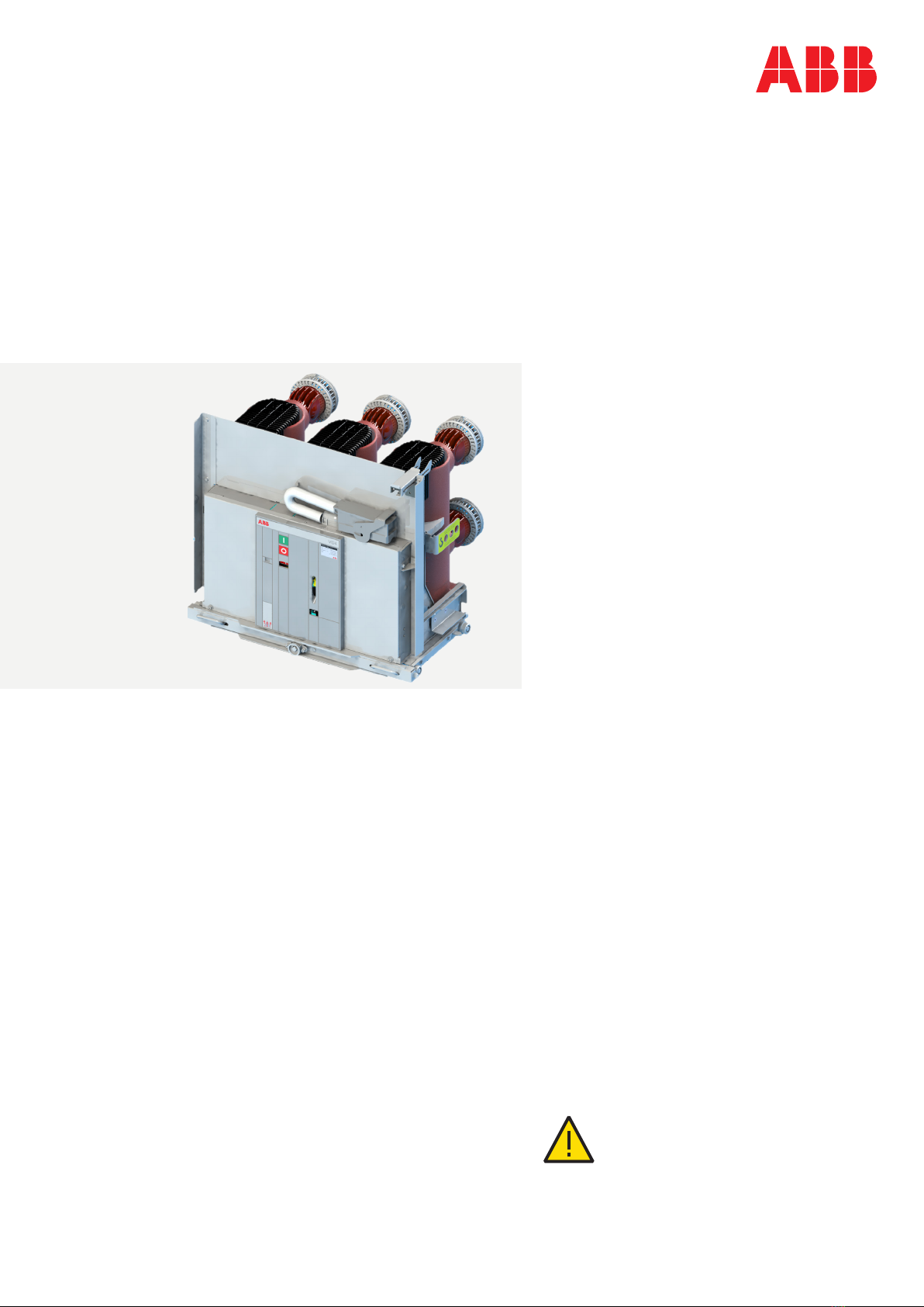
The VD4 are vacuum circuit breaker for indoor
installation.
For the electrical performances, please refer to the
corresponding technical catalogue code
1VCP000001.
For special installation requirements, please contact
ABB.
The following versions are available:
fixed
withdrawable for UniGear ZS1 switchgear
4.2 Reference Standards
The VD4 circuit breakers conform to the IEC 62271-
100, CEI - VDE - BS Standards are equivalent to IEC
Standards due to harmonization with IEC.
4.3 CLASSIC operating mechanism
VD4 circuit breakers are equipped with modular
CLASSIC spring operating mechanisms. The
operating mechanism is designed to cover the
specific range of 63 kA
4.4 Structure and function
4.4.1 Structure of the breaker poles
(Figures 4/2, 4/3 and 4/4)
The basic structure of a vacuum circuit breaker and
a vacuum interrupter is explained in figures 4/2 and
4/3.
The poles, which are constructed in column form,
are mounted on the bracket-shaped rear part of
mechanism enclosure 1. The live parts of the breaker
poles are located in the insulating material pole
tubes 12 and protected from impacts and other
external influences.
With the breaker closed, the current path leads from
the upper breaker terminal 13 and a chamber holder
fixed in the pole tube to the fixed contact 15.2 in the
vacuum interrupter 15, then via the moving contact
15.3 and the roller contact 16.2, to the lower breaker
terminal 14. The switching motion is effected by
means of the insulated coupling rod 18 with internal
contact force springs 17.
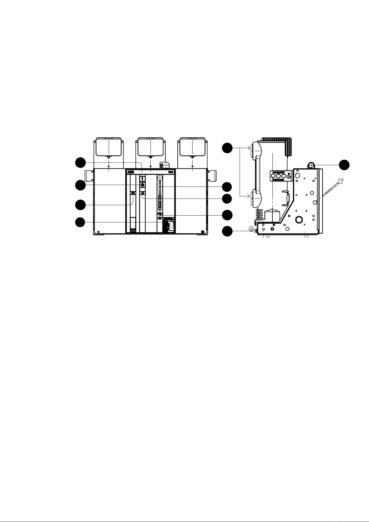
4.4.2 Structure of the breaker operating
mechanism (Figures 4/1, 4/4 and 4/5)
The operating mechanism is of the stored-energy
spring type and acts on the three breaker poles. The
necessary operating energy is stored ready for
activation by charging the spring energy store.
The stored-energy spring mechanism essentially
consists of drum 33 containing the spiral spring, the
charging system, the latching and operating
mechanism and the linkages which transmit the
force to the breaker poles. In addition, there are
supplementary components such as the charging
—
4. Description
motor, releases, auxiliary switches and the controls
and instruments located on the front of the
mechanism enclosure 1.
The basic structure of a stored-energy spring
mechanism is explained in figure 4/4.
The operating mechanism is fundamentally suitable
for auto-reclosing and, due to the short charging
times, also for multi-shot auto-reclosing.
In the basic version of the circuit breaker, the spring
energy store is charged manually. The operating
mechanism can optionally be fitted with a charging
motor.
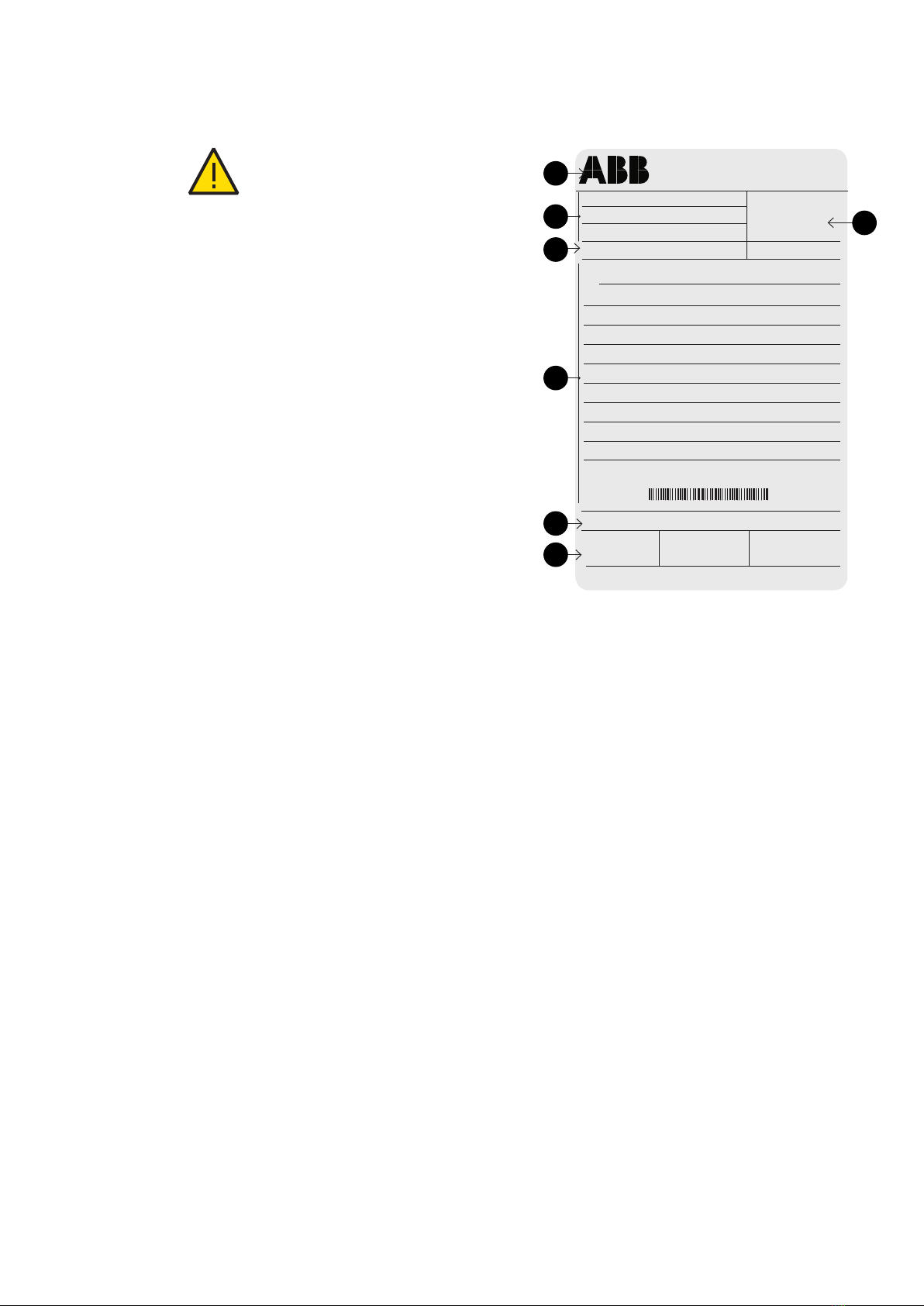
There is one rating plate with the main data of the
switch equipment on front plate 1.1, and another at
the lower front right in mechanism enclosure 1.
The basic version of the stored-energy spring
mechanism is fitted with the following auxiliary
equipment:
Shunt release OFF -MBO1
Five-pole auxiliary switch -BGB2 for annunciation
purposes 38
Auxiliary switch -BGB4 for fault annunciation
Mechanical ON push-button 2
Mechanical OFF push-button 3
Mechanical position indicator 4
Charging condition indicator 8 for the spring
energy store
Mechanical operating cycle counter 5
The following additional equipment can be installed:
Blocking magnet -RLE1 with auxiliary switch -BGL1
Shunt release ON -MBC
Second shunt release OFF -MBO2
Indirect overcurrent release -MBO3
Undervoltage release -MBU
Five-pole auxiliary switches -BGB1 and -BGB3
Charging motor -MAS 36
Five-pole auxiliary switch -BGS1 to switch the
charging motor.
4.4.3 Releases, blocking magnet and auxiliary
switches (Figures 4/1, 4/5, 9/1, 9/2, 9/3)
The releases and the blocking magnet are
mounted at the top left on the spring operating
mechanism.
The allocation of the auxiliary switches can be
seen in the wiring diagram.
The five-pole auxiliary switch -BGS1 is operated by
the charging condition indicator 8. It controls the
charging motor -MAS, serves as an electrical
interlock for shunt release ON -MBC when the
spring mechanism is not sufficiently charged, and
also provides an electrical switching readiness
signal.
Operation of the five-pole auxiliary switches
-BGB1, -BGB2 and -BGB3 is dependent on the
switching position of the circuit breaker.

2 3 4
5
13 11.1
14
16.2
12
17
18
20
19
15
11.1 8 7 6
9
15.2
15.3
15.7
15.1
15.4
15.6
15.5
15
15.3
15.2
17
19
20 21
6
34
33
33
50
32
18
30
9
35
DISTRIBUTION SOLUTIONS 7
Figure 4/1: Circuit breaker front with controls and annunciations
1 Mechanism enclosure
1.1 Front plate
2 ON push-button
3 OFF push-button
4 Position indicator
5 Operating cycle counter
6 Recess for charging lever 9
7 Rating plate
8 Charging condition indicator
9 Charging lever
Figure 4/2: Sectional view of a vacuum circuit breaker,
type VD4, schematic diagram
1 Mechanism enclosure
1.1 Front plate, removable
12 Insulating material pole tube
13 Upper breaker terminal
14 Lower breaker terminal
15 Vacuum interrupter
16.2 Roller contact
17 Contact force spring
18 Insulated coupling rod
19 Opening spring
20 Shift lever pair
Figure 4/3: Partial section of a vacuum interrupter, simplified
schematic diagram (Details vary according
to the specified switching duties)
15.1 Insulator
15.2 Fixed contact
15.3 Movable contact
15.4 Metal bellows
15.5 Screen
15.6 Guide
15.7 Interrupter lid
Figure 4/4: Basic structure of the stored-energy spring mechanism
6 Recess
9 Charging lever
15 Vacuum interrupter
15.3 Movable contact
16.2 Roller contact
17 Contact force spring
18 Insulated coupling rod
19 Opening spring
20 Shift lever pair
21 Cam disk
30 Drive shaft
31 Release mechanism
32 Stop disk
33 Drum with spiral spring
34 Chain drive
35 Ratchet wheel
50 Left-hand control cam

37 35 38
36 31 634
8VD4 - INSTALLATION AND SERVICE INSTRUCTIONS
4.4.4 Mounting of the VD4 -63 kA on trucks from
other manufacturers
VD4 -63 kA generator circuit breakers which are not
installed on ABB withdrawable parts must be fitted
with one or two additional auxiliary switches which
are dependent on the mechanical lock and release
device. These must interrupt the circuit of shunt
release ON -MBC.
Similary to auxiliary switches -BGT2 and -BGT1 in
ABB withdrawable parts, no electrial pulse may
arrive during and before mechanical blocking of the
spindle mechanism, and may only be applied again
after the end of mechanical blocking.
This ensures that the shunt release ON cannot be
loaded with an electrical ON pulse when the
withdrawable part is in an intermediate position,
which could burn out the coil.
Figure 4/5: View of the stored-energy spring mechanism and auxiliary
equipment with the front plate removed
6 Recess for charging lever 9
31 Release and control mechanism on the drive shaft
34 Chain drive
35 Ratchet wheel
36 Charging motor
37 Release and control mechanism area
38 Auxiliary switch block
—
4. Description
Auxiliary switch -BGB1 interrupts the circuit of the
optional additional shunt release OFF -MBO2 with
the circuit breaker in the open position, and the
circuits of shunt release ON -MBC and the optional
blocking magnet -RLE1 with the circuit breaker in
the closed position. There is one further NOC for
other purposes.
On failure or absence of the control voltage,
blocking magnet -RLE1 mechanically locks the ON
half shaft and simultaneously acts on the
corresponding auxiliary switch -BGL1 to interrupt
the circuit of shunt release ON -MBC.
Blocking magnet -RLE1 is accessible when front
plate 1.1 is removed.
Auxiliary switch -BGB2 interrupts the circuit of
shunt release OFF -MBO2 with the circuit breaker
in the open position. One further NOC and three
NCCs are available for annunciation, control and
interlock purposes.
Auxiliary switch -BGB3 can be optionally designed
with any possible combination of contacts from
five NOCs to five NCCs. Its contacts are available
for any required control, annunciation or interlock
functions. The auxiliary switch is normally
configured as shown in electrical diagrams.
The single pole auxiliary switch -BGB4 (fleeting
signal (“breaker released”).
With remote control, the auxiliary switch is
necessarily operated by:
Shunt release OFF -MBO1 or
Shunt release OFF -MBO2 or
Undervoltage release -MBU or
Indirect overcurrent release -MBO3.
Note:
1. Shunt releases OFF (-MBO1) and ON (-MBC) are
exclusively provided for opening and closing in
normal operation. For safety breaking operations,
the second shunt release OFF (-MBO2) must be
used, in most cases with a separate control
voltage supply.
These three releases are of the solenoid type and
suitable for a large number of operating cycles.
2. The undervoltage release (-MBU) and/or indirect
overcurrent release (-MBO3) are pure safety and
protection releases and must not be used for
switching in normal operation.

DISTRIBUTION SOLUTIONS 9
4.5.4 Auto-reclosing sequence
An OFF-ON or OFF-ON-OFF auto-reclosing
sequence is activated and checked by the protection
system. It is necessary for the spiral spring in the
operating mechanism to be in the (re-)charged
condition, with the circuit breaker in the closed
position. The (re-)charging process is carried out
automatically after closing of the breaker on
breakers with motor charging mechanisms, but
must be carried out manually on breakers without
charging motors (or when the charging motor has
broken down). Opening of the breaker is also
possible during the (re-)charging process, but
subsequent closing of the breaker is however
blocked until the charging process has been
completed.
4.5.5 Quenching principle of the vacuum
interrupter
Due to the extremely low static interrupter chamber
pressure of 10-2 to 10-6 Pa, only a relatively small
contact gap is required to achieve a high dielectric
strength. The arc is extinguished on one of the first
natural current zeros.
Due to the small contact gap and the high
conductivity of the metal vapour plasma, the arc
drop voltage, and additionally, due to the short
arcing time, the associated arc energy, are
extremely low, which has advantageous effects on
the life of the contacts and thus on that of the
vacuum interrupters.
4.5 Function
4.5.1 Charging of the spring energy store
(Figures 4/1 and 4/4)
To provide the necessary motive energy, the spring
energy store, either charged automatically by a
charging motor or manually in a vertical pumping
action with charging lever 9, depending on the
equipment fitted to the circuit breaker. The current
charging condition is shown at charging condition
indicator 8.
As a precondition for an auto-reclosing sequence,
the operating mechanism is either (re-)charged
after a closing operation automatically by the
charging motor, or it requires (re-)charging by hand
if the operating mechanism is of the manual type.
4.5.2 Closing procedure
(Figures 4/1, 4/3, 4/4 and 4/5)
The closing process is started by the mechanical ON
push-button 2, or by activation of shunt release ON
-MBC. The release mechanism 31 then permits drive
shaft 30 to be rotated by the (previously) charged
spiral spring. The moving contact 15.3 in vacuum
interrupter 15 is moved until the contacts touch by
cam disk 21 and further kinematic links. In the
further sequence of motion, spring arrangement 17
is tensioned and the appropriate amount of contact
force thus applied. The available overtravel is higher
than the maximum value of contact erosion during
lifetime of the interrupter. During the closing
process, opening springs 19 are simultaneously
tensioned.
4.5.3 Opening procedure
(Figures 4/1, 4/3, 4/4 and 4/5)
The opening procedure is initiated by mechanical
OFF push-button 3 or by activation of one of
releases -MBO1, -MBU, -MBO3 or -MBO2. Observe
the notes in section 3.2.1 on control of the releases.
Release mechanism 31 then permits drive shaft 30
to be turned further by the spring energy store,
which is still sufficiently charged. Opening spring
19, which is thus released, moves contact 15.3 into
the open position at a defined speed.

7
2
1
6
5
10
9
4
3
8
10 VD4 - INSTALLATION AND SERVICE INSTRUCTIONS
Caption
1 Opening pushbutton
2 Closing pushbutton
3 Lever for manual closing spring charging
4 Indicator for circuit breaker open “O” and closed “I”
5 Operation counter
6 Charging condition indicator
7 Cable bushing
8 Rating plate
9 Earthing screw
10 Terminals
Fig. 5
4.6 Fixed circuit breakers
The fixed circuit breaker (fig. 5) is the basic version
complete with structure and front protection
screen. The fixing holes are made in the lower part
of the structure.
The earthing screw is placed in the rear part of the
circuit breaker. For further details please see the
caption to figure 5.
—
4. Description

DISTRIBUTION SOLUTIONS 11
4.7 Standard fittings for fixed
circuit breakers
The basic versions of the fixed circuit breakers are
three-pole and fitted with:
CLASSIC type manual operating mechanism
mechanical signalling device for closing spring
charged/ discharged
mechanical signalling device for circuit breaker
open/closed
closing pushbutton, opening pushbutton and
operation counter
set of ten circuit breaker open/closed auxiliary
contacts
Note: with the set of ten auxiliary contacts supplied as standard and
the maximum number of electrical applications possible, three make
contacts (signalling circuit breaker open) and five break contacts
(signalling circuit breaker closed) are available.
lever for manual closing spring charging
VD4 - 63 kA

12 VD4 - INSTALLATION AND SERVICE INSTRUCTIONS
4.7.1 General characteristics of fixed circuit breakers
General characteristics of fixed circuit breakers (12 kV)
—
4. Description
Circuit breaker VD412
Standards
Rated voltage Ur [kV]
Rated insulation voltage Us [kV]
Impulse withstand voltage Up [kV]
Rated frequency fr [Hz]
Ir [A] )
Rated breaking capacity (rated short-circuit
breaking current symmetrical) Isc [kA]
Ik [kA]
Making capacity Ip [kA]
Operation sequence
Opening time [ms]
Arcing time [ms]
Total breaking time [ms]
Closing time [ms]
Maximum
overall
dimensions
H [mm]
W [mm]
D [mm]
Pole distance P [mm]
Weight [kg]
Standardised table of dimensions
Operating temperature [°C]
Tropicalization
Electromagnetic compatibility
D
W
PP
(1) 4000 A rated currentwth guaranted with forced ventilation according to ABB design

DISTRIBUTION SOLUTIONS 13
4.7.2 General characteristics of fixed circuit breakers
General characteristics of fixed circuit breakers (17.5 kV)
Circuit breaker VD417.5
Standards
Rated voltage Ur [kV]
Rated insulation voltage Us [kV]
Impulse withstand voltage Up [kV]
Rated frequency fr [Hz]
Ir [A] )
Rated breaking capacity (rated short-circuit
breaking current symmetrical) Isc [kA]
Ik [kA]
Making capacity Ip [kA]
Operation sequence
Opening time [ms]
Arcing time [ms]
Total breaking time [ms]
Closing time [ms]
Maximum
overall
dimensions
H [mm]
W [mm]
D [mm]
Pole distance P [mm]
Weight [kg]
Standardised table of dimensions
Operating temperature [°C]
Tropicalization
Electromagnetic compatibility
D
W
PP
(1) 4000 A rated currentwth guaranted with forced ventilation according to ABB design

4
6
2
516
1
7
3
9
13
8
14
11 10
15
14 VD4 - INSTALLATION AND SERVICE INSTRUCTIONS
—
4. Description
4.8 Withdrawable circuit breakers
The 63 kV circuit breakers are available for ZS1
switchgear (see fig. 6).
They consist of a truck on which the supporting
structure of the circuit breaker is fixed.
Circuit breakers for UniGear ZS1 (fig. 6)
The cord with the connector (plug) for connection of
the operating mechanism electrical accessories
comes out of the connection (15).
The strikers for operating the contacts (connected/
isolated) placed in the switchgear are fixed in the
top part of the circuit breaker.
The shutter actuator (9) and roller (18) are provided
for operating the segregation shutters of the
medium voltage contacts of the enclosure or of the
switchgear are fixed on the sides of the circuit
breaker.
The crosspiece with the handles (17) for hooking up
the circuit breaker for the racking-in/out operations
by means of the special operating lever (16) is
mounted on the front part of the circuit breaker
truck.
The circuit breaker is completed with the isolating
contacts (8).
The withdrawable circuit breaker is fitted with
special locks on the front crosspiece, which allow
hooking up into the corresponding couplings of the
switchgear.
The locks can only be activated by the handles with
the truck fully resting against the crosspiece.
The operating lever (16) must be fully inserted. A
lock prevents the truck from advancing into the
enclosure or fixed part when the earthing switch is
closed.
Another lock prevents racking-in and racking-out
with the circuit breaker closed. With the truck in an
intermediate position between isolated and
connected, a further lock prevents circuit breaker
closing (either mechanical or electrical).
A locking magnet is also mounted on the truck
which, when de-energised, prevents the truck
racking-in operation.
On request, an interlock is available which prevents
racking-in of the circuit breaker with the door open,
and door opening with the circuit breaker closed.
The lever for loading the closing spring (1) in the
manual mode is built into the operating mechanism.
The spring is loaded by repeatedly lowering the lever
with linear movements until the yellow indicator (6)
appears to show that loading is complete.
The spring can only be loaded with the switchgear
door open.
Caption
1 Lever for manually charging the closing spring
2 Signalling device for circuit breaker open/closed
3 Rating plate
4 Opening pushbutton
5 Closing pushbutton
6 Signalling device for closing spring charged/discharged
7 Operation counter
8 Isolating contacts
9 Slide for operating the switchgear shutters (UniGear ZS1, PowerCube,
ZS8.4)
Fig. 6
10 Truck
11 Locks for hooking into the fixed part
12 Mechanical override of the undervoltage release (on request)
13 Cabling connection
14 Operating lever for circuit breaker racking-in/out
15 Handles for activating the locks (11)
16 Shutters actuator (for UniSec version only)

DISTRIBUTION SOLUTIONS 15
4.9 Standard fittings of
withdrawable circuit breakers
for UniGear ZS1 switchgear
The basic versions of the withdrawable circuit
breakers are three-pole and fitted with:
CLASSIC type manual operating mechanism
mechanical signalling device for closing spring
charged/discharged
mechanical signalling device for circuit breaker
open/closed
closing pushbutton
opening pushbutton
operation counter
set of ten auxiliary circuit breaker open/closed
contacts
Note: with the set of ten auxiliary contacts supplied as standard and
the maximum number of electrical applications possible, three make
contacts (signalling circuit breaker open) and four break contacts
(signalling circuit breaker closed) are available.
lever for manually charging the closing spring
isolating contacts VD4/P 63 kA
Comply with the instructions in the UniGear
switchgear manual for the operations that can be
performed with the door open.
Note: on request, the closing spring loading device for withdrawable
circuit breakers for UniGear switchgear can be supplied with the lever
outside the operating mechanism and a rotary loading movement. This
device is part of the standard equipment for VD4/ZS8 withdrawable
circuit breakers only. This rotary loading device allows the closing spring
to be loaded with the switchgear door closed.
cord with connector (plug only) for auxiliary
circuits, withstriker pin which does not allow
connection of the plugin the socket if the rated
current of the circuit breaker isdifferent from the
rated current of the panel
racking-in/out lever (the quantity must be defined
according to the number of pieces of apparatus
ordered)
locking electromagnet in the truck. This prevents
the circuit breaker from being racked into the
panel with auxiliary circuits not connected (plug
not inserted in the socket).

16 VD4 - INSTALLATION AND SERVICE INSTRUCTIONS
—
4. Description
4.9.1 General characteristics of withdrawable circuit breakers
for UniGear ZS1 switchgear
General characteristics of withdrawable circuit breakers
for UniGear ZS1 switchgear (12 kV)
Circuit breaker VD4/P12
Standards
Rated voltage Ur [kV]
Rated insulation voltage Us [kV]
Impulse withstand voltage Up [kV]
Rated frequency fr [Hz]
) Ir [A] )
Rated breaking capacity (rated short-circuit
breaking current symmetrical) Isc [kA]
Ik [kA]
Making capacity Ip [kA]
Operation sequence
Opening time [ms]
Arcing time [ms]
Total breaking time [ms]
Closing time [ms]
Maximum
overall
dimensions
H [mm]
W [mm]
D [mm]
Pole distance P [mm]
Weight [kg]
Standardised table of dimensions
Operating temperature [°C]
Tropicalization
Electromagnetic compatibility
D
W
PP
(1) 4000 A rated currentwth guaranted with forced ventilation according to ABB design

DISTRIBUTION SOLUTIONS 17
4.9.2 General characteristics of withdrawable circuit breakers
for UniGear ZS1 switchgear
General characteristics of withdrawable circuit breakers
for UniGear ZS1 switchgear (17.5 kV)
Circuit breaker VD417.5
Standards
Rated voltage Ur [kV]
Rated insulation voltage Us [kV]
Impulse withstand voltage Up [kV]
Rated frequency fr [Hz]
) Ir [A] )
Rated breaking capacity (rated short-circuit
breaking current symmetrical) Isc [kA]
Ik [kA]
Making capacity Ip [kA]
Operation sequence
Opening time [ms]
Arcing time [ms]
Total breaking time [ms]
Closing time [ms]
Maximum
overall
dimensions
H [mm]
W [mm]
D [mm]
Pole distance P [mm]
Weight [kg]
Standardised table of dimensions
Operating temperature [°C]
Tropicalization
Electromagnetic compatibility
D
W
PP
(1) 4000 A rated currentwth guaranted with forced ventilation according to ABB design

Number of operating cycles n
18 VD4 - INSTALLATION AND SERVICE INSTRUCTIONS
Fig. 7: VD4 63kA for 17.5kV, 275mm pole centers,
mechaism side
Fig. 7a: Permissible number of vacuum interrupter operating
cycles n as a function of the breaking current Ia
4.10 Permissible number of vacuum interrupter switching operations in
relation to breaking current
Diagram A
—
4. Description

DISTRIBUTION SOLUTIONS 19
Climate
To avoid the risk of corrosion or other damage in areas:
with a high level of humidity, and/or
with rapid and big temperature variations, take
appropriate steps (for example, by using suitable electric
heaters) to prevent condensation phenomena.
For special installation requirements or other
operating conditions, please contact ABB.
The areas involved by the passage of
power conductors or auxiliary circuit
conductors must be protected against
access of any animals which might cause
damage or disservices.
5.1 General
Correct installation is of primary
importance. The manufacturer’s
instructions must be carefully studied
and followed. It is good practice to use
gloves for handling the pieces during
installation.
5.2 Installation and operating
conditions
The following Standards must be taken into
particular consideration during installation and
service:
IEC 62271-1/DIN VDE 0101
VDE 0105: Electrical installation service
DIN VDE 0141: Earthing systems for installations
with rated voltage above 1 kV
All the accident prevention regulations in force in
the relative countries.
5.2.1 Normal conditions
Follow the recommendations in the IEC 62271-1 and
62271- 100 Standards. In more detail:
Ambient temperature
Maximum
apparatus for indoor installation
Humidity
The average value of the relative humidity, measured for a period
The average value of the pressure of the water vapour, measured
The average value of the relative humidity, measured for a period
The average value of the pressure of the water vapour, measured
Altitude
<
5.2.2 Special conditions
Installations over 1000 m a.s.l.
Possible within the limits permitted by reduction of the
dielectric resistance of the air.
Increase in the ambient temperature
Reduction in the rated current.
Encourage heat dissipation with appropriate additional
ventilation.
—
5. Installation

20 VD4 - INSTALLATION AND SERVICE INSTRUCTIONS
5.3 Preliminary operations
Clean the insulating parts with clean dry cloths.
Check that the top and bottom terminals are clean
and free of any deformation caused by shocks
received during transport or storage.
5.4 Installation of fixed circuit
breakers
The circuit breaker can be mounted directly on
supporting frames to be provided by the customer,
or on a special supporting truck (available on
request).
The circuit breaker, with supporting truck, must be
suitably fixed to the floor of its own compartment
by the customer.
The floor surface in correspondence with the truck
wheels must be carefully levelled.
A minimum degree of protection (IP2X) must be
guaranteed from the front towards live parts.
5.4.1 Mounting the circuit breaker on a truck made
by other manufacturers
The VD4 circuit breakers which are not installed on
ABB trucks, but on trucks made by the customer,
must be fitted with one or two additional auxiliary
contacts (activated by the mechanical lock and by
the circuit breaker release device) to carry out the
function of interrupting the shunt closing release
circuit (-MBC) during traverse from isolated and vice
versa.
In ABB trucks, this function is carried out by the
-BGT1 and -BGT2 auxiliary contacts which cut of the
release power supply during and before activation
of the mechanical lock of the screw truck racking-in
device. This means that the shunt closing release
power supply can only by applied at the end of
activation of the mechanical lock. In this way it is
certain that no electrical impulse can activate the
shunt closing release with the circuit breaker in an
intermediate position.
5.5 Installation of withdrawable
circuit breaker
The withdrawable circuit breakers are preset for use
in UniGear ZS1.
For racking-in/racking-out of the switchgear, fully
insert the lever in the appropriate seat and work it
clockwise for racking-in, and anti-clockwise for rack-
ing-out, until the limit switch positions are reached.
Circuit breaker racking-in/-out must be carried out
gradually to avoid shocks which may deform the
mechanical interlocks and the limit switches.
The torque normally required to carry out racking-in
and racking-out is <25 Nm.
This value must not be exceeded. If operations are
prevented or difficult, do not force them and check
that the operating sequence is correct.
Note
To complete the racking-in/out operation, about 20 rotations of the lever
are required for circuit breakers up to 17.5 kV, and about 30 rotations for
24 kV circuit breakers.
When the circuit breaker has reached the isolated
for test/ isolated position, it can be considered
racked into the switchgear and, at the same time,
earthed by means of the truck wheels.
Withdrawable circuit breakers of the same version,
and therefore with the same dimensions, are
interchangeable.
However, when, for example, different electrical
accessory fittings are provided, a different code for
the plug of the auxiliary circuits does not allow
incorrect combinations between panels and circuit
breakers.
For the circuit breaker installation operations, also
refer to the technical documentation of the
abovementioned switchgear.
•The racking-in/-out operations must
always be carried out with the circuit
breaker open.
•When putting into service for the first
time, it is advisable to charge the
circuit breaker operating mechanisms
manually so as not to overload the
auxiliary power supply circuit.
—
5. Installation
Other manuals for VD4 Series
11
Table of contents
Other ABB Industrial Equipment manuals
Popular Industrial Equipment manuals by other brands

Shini
Shini SAL-810 manual

Bondtech
Bondtech DDG Ultimaker V2.0 Assembly and installation manual

FRANKLINWH
FRANKLINWH aPbox Installation and operation manual

matev
matev FPS JD-2026R operating manual

UnionSpecial
UnionSpecial BCE300PD Original instructions

Trane
Trane Tracer CH530 Installation, operation and maintenance

BOCI
BOCI BLT540H product manual

Steris
Steris Basil 1000 Operator's manual

ITOH DENKI
ITOH DENKI POWER MOLLER IB-P03 Technical documentation

BAC
BAC VTL Operating and maintenance instructions

Prism Hardscapes
Prism Hardscapes PH Ignite Instruction, Operation & Maintenance

AeroFlow
AeroFlow HOLDEN instruction manual