6
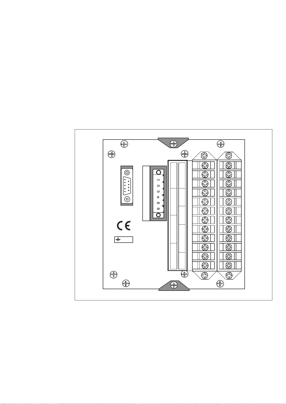
Connections Thethreephase-currentsoftheovercurrentpro-
tection are connected to terminals 1-2, 4-5 and
7-8, when the rated current of the secondary
circuits is In= 5 A. When using current trans-
formers with a rated current of 1 A, terminals
1-3,4-6and7-9areused.Theovercurrent pro-
tectionmay alsobeusedinsingle-phaseortwo-
phase applications, in which case inputs not to
be used are left unconnected. In single-phase
applications,however,wiring the phasecurrent
through two current inputs in series may in-
creasetheoperatingspeed of the relay, particu-
larly for instantaneous operations.
The neutral current of the earth-fault protec-
tion is connected to terminals 25-27 when the
ratedcurrentis1Aandtoterminals25-28when
the rated current is 0.2 A.
The control input 10-11 can be used in three
different ways, as the control input of an exter-
nalblockingsignalfor themeasuringmodules,
asthecontrolinputforunlatchingthe trip relay,
or as the control input for the remote control
of settings. The function is selected by means
of switches 1...8 of switchgroup SGB in the
main menu of the measuring relay module.
Theauxiliarysupplyvoltageoftherelay iscon-
nected to the terminals 61-62. At d.c. auxiliary
supply voltage the positive lead is connected to
terminal 61. The level of the voltage to be ap-
pliedtothe terminals is determinedbythetype
of power supply and output relay module in-
serted in the protection. For further details see
thedescriptionofthepowersupplymodule.The
auxiliary voltage range of the relay has been
marked on the front panel.
Output relay A provides the CB tripping com-
mandssothattheCBoperatesoncetheoperat-
ing time of the low-set or high-set stage of the
overcurrentornon-directionalearth-faultmod-
ule has elapsed. The stages to perform a trip-
ping are selected with switches 2,4,6 and 8 of
switchgroup SGR1. On delivery from factory
all stages are selected to perform tripping. A
latching function of the output relay A can be
selected by means of switches SGB 6 and 7 for
overcurrent and earth-fault trippings.
Thetripalarmsignalsfromthemeasuringmod-
ules are obtained through output relays B and
C. The signals to be forwarded to the output
relays B and C are selected with switches1...8
of switchgroup SGR2 of the measuring mod-
ule. The switch matrixes for configuration of
the control signals of the output relays B and C
identical. Normally the output relays B and C
are given such a configuration that low-set and
high-setovercurrenttripalarmsignalisobtained
over relay C and the corresponding alarm sig-
nal for the earth-fault trips via output relay B.
This is also the default setting on delivery.
The starting signals from the protective stages
of the relay are received through output relay
D. The signals to be forwarded to the output
relayDareselectedbymeansofswitches1,3,5
and 7 of switchgroup SGR1 which is found in
the main menu of the measuring module. The
startingsignalsofthelow-setand high-set stage
oftheovercurrentunitareselectedwithswitches
1 and 3, whereas switches 5 and 7 convey the
corresponding signals of the non-directional
earth-fault unit.
OutputrelayE,terminals74-75,isaheavyduty
output relay capable of controlling a circuit
breaker, like the main trip relay A. Relay E is
usedmainlyforbringingoutanystartingortime
delayedsignalforstartingofauto-reclosures,for
signalling or counting purposes or for auxiliary
trip. Output relay E is also used as a tripping
outputforthecircuitbreakerfailureprotection,
CBFPwhentheCBFPfunctionisused. Inthis
casethetrip signal canbeused either to control
a circuit breaker upstreams or to control a sec-
ondtripcoilonthemaincircuitbreakertogive
a higher redundancy to the breaker operation.
OutputrelayF,terminals70-71-72,operatesas
the output relay of the self-supervision system
of the relay. The relay operates on the closed-
circuit principle so that in normal service con-
ditionsthecontactgap70-72isclosed.Ifafault
is detected by the self-supervision system, or if
thereisafailureintheauxiliarysupply,theout-
putrelaydropsoffprovidinganalarmsignalby
closing the NO contact 71-72.
The relay is interfaced with a data transmission
busthrougha9-pole,D-typesubminiaturecon-
nector located at the rear panel of the relay. By
means of bus connection modules SPA-ZC 17
or SPA-ZC 21, the overcurrent and earth-fault
relay can be linked to the fibre-optic bus. The
terminalsofthefibre-opticcablesareconnected
to the counter terminals Rx and Tx of the bus
connection module. The fibre-optic cables are
linked from one protection to another and to
the substation level communication unit, for
instance type SRIO 1000M.