4 Product manual | OVRHS3/OVRHS3U surge protective devices
Important safety instructions
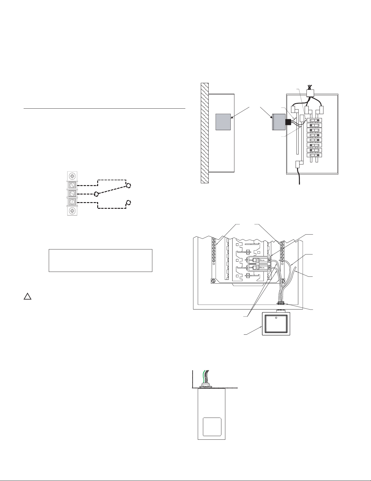
Installation
Refer to Table 1 to see if an upstream overcurrent protection
device is required. Type 1 SPD devices do not require upstream
overcurrent protection, but Type 2 SPDs must be installed
behind an overcurrent protection device. The suppressor must
be installed on the load side of the main service disconnect.
The unit must be installed in parallel to the electrical distribution
system. Careful consideration should be made in selecting the
knockout location because excess lead length and sharp bends
in the wire drastically decrease the effectiveness of the SPD.
For this reason choose a knockout location that minimizes lead
length and sharp bends. The SPD may also be mounted by it’s
metal bracket (option) within the equipment enclosure.
1. Disconnect all power supplying the electrical panel.
2. Remove the panel screws and cover. Retain these parts for
re-installation.
3. Either remove a knockout 13mm (0.5 inches) or install
provided metal bracket (option).
4. Remove lock washer from the SPDs threaded nipple.
Carefully feed the wires through to avoid cutting wire
insulation. Slide lock washer over the wires to anchor the
threaded nipple. Rotate the SPD so that the function status
LED indicators can be easily viewed. Tighten the lock washer
to secure the SPD.
5. Locate the neutral bar inside the electrical panel and connect
the white or blue wire to the neutral bar and tighten to torque
specified on inside of panel. Keep conductor length as short
as possible and avoid sharp bends in the wire.
6. Locate the ground bar inside the electrical panel. Connect
the green/yellow wire to the ground bar and tighten the
terminal to the torque specified on the panel. Keep conductor
length as short as possible and avoid sharp bends. If neutral
is bonded to ground, green wire may be terminated to
neutral.
7. Black or brown wires (model dependent) should be
connected to either the breaker or the bus of the panel,
as long as the short circuit current rating does not exceed
65 or 100kAIC (see Table 1 for specific model ratings). On
the OVRHS3401203H (120/240 High-Leg Delta) protector
connect the orange wire to phase B (the high leg). If you
would like to be able to turn the unit off, then you may
consider connecting it to a breaker (# of breaker pole
positions determined by the # of black or brown wires
provided with the unit). Tighten terminals to torque specified
on inside of panel. Keep lead lengths as short as possible
and avoid sharp bends.
8. Re-install panel cover.
Operation
1. Apply power to the panel. If the electrical and grounding
wirings are done correctly, the green function status LED will
illuminate. If the LED does not turn on, remove the power and
review all of the previous installation procedures.
2. If after a known heavy lightning strike has occurred and
the LED is off, reset the breaker if the OVRHS3 is tied to a
breaker. If the LED light(s) come(s) back on then the protector
is fine. If the LEDs are still out, or you can not reset the
breaker, the protector must be replaced. This unit contains
no user serviceable parts.