ABB TPME Series User manual

• Model numbers covered by this manual
are TPME and TPHE, UL Type 2 model
types ending with part number suffixes
of NSBX and NSWM. (Example:
TPHE277Y20NSBX)
• Model types are also available with a
UL Type 1 rating. These models will be
labeled with the part number suffix of T1.
—
INSTALLATION, OPERATION AND MAINTENANCE MANUAL
TPME and TPHE NSBX and NSWM series
Integral SPDs for OEM factory installation

B1 copy starts here
B2 copy starts here
B3 copy starts here
Headline starts here
2
TPME AND TPHE NSBX AND NSWM SERIES INTEGRAL SPDS
—
Guide to installation and assistance
WARNING
The SPD warranty is voided if the unit is damaged as a
result of improper installation. Improper installation or
misapplication may result in serious personal injury or
damage to the electrical system. Read the complete
installation instructions before proceeding with
installation.
La garantie du SPD est annulée si l’appareil est
endommagé à la suite d’une mauvaise installation. Une
mauvaise installation, ou utilisation, peut entraîner des
blessures graves ou des dégâts au système électrique.
Lisez les instructions d’installation en intégralité avant
de procéder à l’installation.
WARNING
The equipment covered by these instructions should
be installed and serviced only by competent qualified
personnel utilizing proper safety practices and
procedures. These instructions are written for such
personnel and are not intended as a substitute for
adequate training and experience in safe procedures
for this type of equipment.
L’équipement couvert par ces instructions doit être installé
et entretenu uniquement par un personnel compétent et
qualifié, utilisant des pratiques et des procédures de
sécurité appropriées. Ces instructions sont rédigées à
l’intention de ce personnel et ne sauraient se substituer
à une formation adéquate et à une expérience des
procédures de sécurité pour ce type d’équipement
WARNING
Remove all power to the electrical panel before installing
or servicing the SPD. All work must be performed by
licensed and qualified personnel. Follow applicable
electrical codes and regulations for the country/location
in which the unit is being used.
Coupez l’alimentation du panneau électrique avant
d’installer ou de procéder à l’entretien du SPD. Tous les
travaux doivent être effectués par un personnel qualifié et
agréé. Respectez les codes et réglementations électriques
en vigueur dans le pays / lieu où l’appareil est utilisé.
WARNING
Do not HIPOT the SPD unit or the electrical system to which
the SPD unit is connected without disconnecting the SPD unit’s
conductors, including phases, neutral and ground.
Ne procédez PAS à des ESSAIS DE RIGIDITÉ DIÉLECTRIQUE sur
le SPD ou le système électrique auquel il est connecté sans
déconnecter les conducteurs des SPD, y compris les phases,
le neutre et la terre.
WARNING
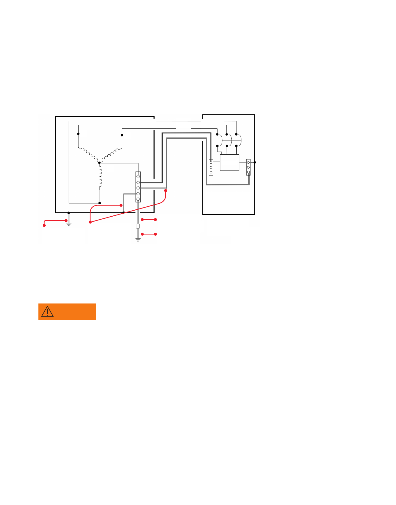
Check to ensure that a proper bond is installed between neutral
and ground at the transformer upstream from all 3-phase wye,
3-phase high-leg or 2-phase SPD devices. If the transformer is
not accessible, check the main service disconnect/panel for the
NG bond. Lack of a proper bond may damage the SPD and void
the warranty. Failure to provide this bond, as required per article
250.30 of the National Electrical Code, can result in elevated
phase-to-ground source voltage potentials. These voltages can
cause damage to electrical equipment as well as safety hazards
including fire, electrical shock, serious injury or death.
Vérifiez qu’une liaison correcte est installée entre le neutre et
la terre au niveau du transformateur en amont de tous les SPD
triphasés en étoile, triphasés en triangle ou biphasés. Si le
transformateur n’est pas accessible, vérifiez la liaison NG sur
le sectionneur / panneau de service principal. L’absence d’une
liaison appropriée peut endommager le SPD et annuler la
garantie. L’absence de cette liaison, telle que requise par l’article
250.30 du Code national de l’électricité, peut entraîner des
potentiels de tension élevés entre la phase et la terre. Ces
tensions peuvent causer des dégâts aux équipements électriques
ainsi que des risques en matière de sécurité, notamment des
incendies, des chocs électriques, des blessures graves ou la mort.
WARNING
Installation by person with electrotechnical expertise only.
WARNUNG!
lnstallation nur durch elektrotechnische Fachkraft.
AVERTISSEMENT!
lnstallation uniquement par des personned qualifiées
électrotechnique.
IADVERTENCIA!
La instalación deberá ser realizada únicamente
por electricistas especializados.

B1 copy starts here
B2 copy starts here
B3 copy starts here
Headline starts here
3
Prior to energization of the SPD, it is critical that the
following items have been addressed. Do not attempt
to energize the SPD or continue with the installation
if all these conditions have not been met, or are unknown.
1. System configuration and voltage
CAUTION
Prior to installation, ensure the system configuration
and voltage is equivalent to the SPD unit being installed.
Avant l’installation, assurez-vous que la configuration et
la tension du système sont équivalentes à celles du SPD
en cours d’installation.
The SPD model number can be found on the UL label
affixed to the SPD enclosure. The SPD selection can be
verified by comparing the model number to the correct
electrical system described in the “VOLTAGE RATINGS
AND POWER SOURCE CONFIGURATIONS” chart.
2. System grounding and bonding
Verify that an NEC (National Electrical Code) compliant
X0 bond has been made at the upstream transformer
or other separately derived system that feeds the SPD.
Per NEC Article 250.30, this bond must be in place on
all 3-Phase WYE, 3-Phase Hi-Leg Delta and Single-Phase
Split-Systems. Refer to diagram "EXAMPLE OF AN NEC
COMPLIANT GROUNDING ARRANGEMENT FOR A
SEPERATELY DERIVED SYSTEM" for an example
of an installation that complies with these NEC
recommendations.
Verify that there have not been multiple instances
of neutral-to-ground bonds on the electrical system.
These bonds, while either intentional or accidental,
result in ground currents that can create differential
voltage potentials between neutral and ground.
Redundant neutral-to-ground connections can result
in damage to the SPD and are in violation of the NEC.
—
Pre-installation requirements
3. SPD installation on ungrounded power systems
Ungrounded power systems are inherently unstable
and can produce excessively high line-to-ground voltages
during certain fault conditions. During these fault
conditions, any electrical equipment, including an SPD,
may be subjected to voltages that exceed their designed
ratings. This information is being provided to the user so
that an informed decision can be made before installing
any electrical equipment on an ungrounded power system.
4. SPD location / primary overcurrent protection
Per the National Electrical Code (NEC Article 285), Type 2
SPDs are allowed to be placed on the load side of the main
service breaker/fuse.
GUIDE TO INSTALLATION AND ASSISTANCE, PRE-INSTALLATION CHECKLIST

B1 copy starts here
B2 copy starts here
B3 copy starts here
Headline starts here
—
Pre-installation requirements
L1
L1
L1
L1
L1
L1
N
N
N
N
L2
L2
L2
L2
L2
—
Model
Nominal voltage
Maximum continuous
operating voltage
System type Source configuration
Single-phase
Dual-phase
Three-phase
WYE,
Three-phase
Delta,
Three-phase
WYE,
Phase A & C
Phase B
Three-phase
Delta Hi-Leg,
L2
L3
L3
L3
4
TPME AND TPHE NSBX AND NSWM SERIES INTEGRAL SPDS

B1 copy starts here
B2 copy starts here
B3 copy starts here
Headline starts here
PRE-INSTALLATION REQUIREMENTS, INSTALLATION
—
Installation
—
The illustration shown provides a recommended
method for grounding a separately derived power
system, per the National Electrical Code, Article
250.30. Please check with the local municipality
or governing authority for additional codes or
other approved regulatory requirements before
attempting to configure any electrical power
distribution system.
—
Example of an NEC compliant grounding arrangement for a separately derived system
Neutral
Primary dist. panel
with overcurrent or
service disconnect means
Grounding electrode
Ref. NEC250-30 (1)(4)
Note:
Primary transformer
windings not shown
for simplicity
Equipment grounding
conductor ref. NEC
250.32 (B)(1)
Bonding jumper
Ref. NEC250 -30(a)(1)
SPD
N G
Phase C
X2 X1
X0
X3
Phase B
Phase A
Grounding electrode
conductor ref. NEC
250.62 -250.64 -250.66
—
Pre-installation requirements
WARNING
Power must be proven disconnected before starting
installation, inspection or maintenance. Failure to do so
may cause serious injury, death and/or property damage.
Il doit être prouvé que l’alimentation est déconnectée avant
de commencer l’installation, l’inspection ou l’entretien. Le
non-respect de cette précaution peut entraîner des blessures
graves, la mort et/ou des dégâts matériels.
The SPDs described in this manual are intended to arrive at
the job site as factory-mounted and wired into OEM electrical
panels or gear. When receiving the SPD on site as OEM factory
preinstalled, please begin at step number 5 below.
are intended to provide guidance to OEMs for factory
installation considerations.
Before attempting installation, make sure that the pre-
installation requirements of this manual have been satisfied.
If the status of the pre-installation requirements are not
known, do not attempt to continue.
The SPD is configured with a mounting base to allow for
secure attachment to the equipment frame. The SPD can
be installed in any orientation; however, special
consideration should be given to allow for periodic
inspection of the diagnostic display panel. The SPD should
be installed as close to the power source as possible to
provide the best SPD performance. The SPD mounting base
should always be secured to a structure that is intended to
be grounded.
Mechanical terminals are provided on the SPD for
connection to the electrical power system. These terminals
will accommodate #14 to 2/0 AWG stranded copper
conductors. The minimum recommended wire size for the
SPD is #6 AWG. See following diagram for terminal location
and identification.
5

B1 copy starts here
B2 copy starts here
B3 copy starts here
Headline starts here
—
Installation
—
Pre-installation requirements
The length of wiring to the SPD must be kept at a minimum.
For the best performance, ABB recommends maintaining
36" of length or less for each conductor (including neutral
and/or ground). Wire lengths should be short, straight runs
between the SPD and power source. Wiring impedance can
be further reduced by twisting the phase, neutral and
ground conductors together and routing them in the same
raceway or channel. Always avoid sharp bends when routing
SPD connecting conductors.
A dedicated circuit breaker is not required for TPME or
TPHE models. If a dedicated branch breaker is to be used
to connect the SPD to the power system, ABB recommends
a 60 A or higher rated breaker.
5. Remote alarm contacts
Remote alarm monitoring contacts are provided on all
SPD model types covered by this manual. If this type of
monitoring is desired, refer to the following diagram for
the location and pin configuration of these contacts. The
contacts are dry, form C type, rated 120 V AC, 1 A (30 V DC,
2 A) maximum. Once the SPD has been energized and is
operating as intended, the alarm contacts will switch to
“normal status.” The contacts will only change back to
“alarm status” if there is a failure within the SPD
suppression circuitry, or if power has been disconnected
from the SPD. Allowing the remote alarm contacts remain
unconnected will not affect the performance or integrity
of the SPD.
6. SPD disconnect switch
Not provided on NSBX or NSWM models.
Once all of the pre-installation conditions have been met
and the SPD has been installed, the SPD can now be
energized. For SPD operational status, refer to Operation
and Maintenance sections.
NOTICE
Hi-Leg Delta power systems:
TPME240H and TPHE240H SPD model types are intended for
Hi-Leg Delta systems and are configured with Phase B as the
intended Hi-Leg connection point. Attempting to connect the
SPD Phase C or Phase A conductor to the system Hi-Leg will
result in immediate SPD failure.
—
Power terminals and remote alarm locations
Phase C/line 3
Ground
Neutral
Phase B/line 2
Phase A/line 1
Normal status indication:
NO - COM = Closed
NC - COM = Open
Alarm status indication:
NO - COM = Open
NC - COM = Closed
—
The illustration above represents the SPD in a vertical orientation. Other orientations
are possible depending on the type of equipment in which the SPD is installed. The
SPD features will be the same regardless of application.
6
TPME AND TPHE NSBX AND NSWM SERIES INTEGRAL SPDS

B1 copy starts here
B2 copy starts here
B3 copy starts here
Headline starts here
WARNING
Upon energization of the SPD, if any of the lamps or
alarms indicates an abnormal condition, power should
be disconnected promptly from the SPD. The electrical
system should be inspected and the pre-installation
requirements should be validated. Do not attempt to leave
power applied to the SPD, or re-energize the SPD in the event
of an alarm condition.
Lors de la mise sous tension du SPD, si l’une des lampes ou des
alarmes indique une condition anormale, l’alimentation du SPD
doit être coupée rapidement. Le système électrique doit être
inspecté et les exigences de pré-installation doivent être
validées. N’essayez pas de laisser le SPD sous tension, ou de le
remettre sous tension en cas d’alarme.
After applying power to the SPD, verify that the protection
monitoring circuits are functioning correctly. If all status
alarms indicate “normal,” the SPD has been successfully
installed and is operational.
1. Line status indicator LEDs
The green line status LEDs provide visual indication of
SPD health status. As long as the SPD is connected to the
electrical system supply voltage and the SPD suppression
circuitry is functional, the line status indicators will be
illuminated green. There is one green indicator per each
protected phase.
2. Alarm status indicator LEDs
When illuminated, the red alarm status indicator LED will
provide notification of an SPD failure condition. Verify the
alarm status indicator is not illuminated upon startup.
3. Remote alarm contacts
Remote alarm contacts are available to remotely monitor
the health status of the SPD. An alarm condition will result
in a status change of the contacts. These contacts do not
affect the performance of the SPD and are not required to
be connected for the SPD to function as intended. (See
alarm contact for details)
4. Test / enable / disable switch
- Enable position — This is the normal position for the tri-
position switch. In the enable position, the audible alarm
will sound in the event of a SPD failure mode.
- Disable position — This position will silence the audible
alarm if desired. The disable switch will not disable or
disconnect the SPD from the electrical power system.
—
Operation
—
Installation
—
SPD display panel
Surge Protective Device
Surge counter
Alarm
Alarm
Test
Enable
Disable
Test
Enable
Disable
STATUS
SPD 100% operational when lit green
STATUS
SPD 100% operational when lit green
2010013902
Surge counter
reset button
Line status
indicator LEDs
Surge counter
LCD display
Test/enable/
disable switch
Alarm indicator LED
7INSTALLATION, OPERATION

—
Maintenance
Should a condition occur that results in premature failure of
the SPD, the integral SPD suppression thermal fusing will safely
interrupt current flow through the SPD without disrupting power
to the protected equipment. This will remove the SPD from the
power system, and the load equipment will remain unprotected
from subsequent surge activity until the SPD is replaced.
If a change in operational status/alarm indication occurs, a
qualified (licensed) electrician should inspect the electrical
system to verify electrical system integrity. If the SPD remains
in alarm after inspection/corrections have been made, the SPD
should be replaced.
—
Servicing/troubleshooting
ABB does not provide a specific schedule for preventative
maintenance as conditions will vary based on location and
the environmental factors presented at each installation site.
However, periodic inspections should be scheduled to verify
that the SPD does not indicate a failure mode. Inspections
should also be made to check the integrity of the electrical
supply connections to the SPD to ensure continued reliable
performance.
The unit’s heavy-duty construction is designed to provide
years of uninterrupted service.
The unit contains no serviceable parts.
L’unité ne contient aucune pièce réparable.
NOTICE
In the event of an SPD alarm condition, do not attempt to
dis-assemble the SPD to replace fusing or other components.
The SPD contains thermally protected MOVs that will only open
when the SPD has failed in a non-serviceable condition. The
entire SPD must be replaced.
En cas de condition d’alarme du SPD, n’essayez pas de démonter
le SPD pour remplacer les fusibles ou d’autres composants. Le
SPD contient des MOV protégés thermiquement qui ne s’ouvrent
que lorsque le SPD tombe en panne et ne fonctionne plus.
L’ensemble du SPD doit être remplacé.
- Test position — The test switch provides a quick diagnostic
status of the audible alarm, alarm status indicator and remote
alarm contacts. When pressed, the audible alarm will sound,
the alarm lamp will illuminate, and the remote contacts will
change state. The “test” position is momentary. Once pressed,
the switch will automatically reset to the enable position
upon release.
5. Surge counter LCD
The surge counter will sense and record transient surge events
that have been mitigated by the SPD. The counter has been
designed to detect transients that exceed the peak sine wave
by more than 70%. If desired, the surge counter display can be
reset to zero at any time by pressing the reset button located
on the LCD display.
—
Operation
2020013601-7.2020
—
We reserve the right to make technical
changes or modify the contents of this
document without prior notice. With regard
to purchase orders, the agreed particulars
shall prevail. ABB Inc. does not accept any
responsibility whatsoever for potential
errors or possible lack of information in
this document.
We reserve all rights in this document
and in the subject matter and illustrations
contained therein. Any reproduction or
utilization of its contents – in whole or in
parts – is forbidden without prior written
consent of ABB Inc. Copyright© 2020 ABB.
All rights reserved.
—
ABB Inc.
305 Gregson Drive
Cary, NC 27511
electrification.us.abb.com/
products/surge-protective-devices
This manual suits for next models
21
Table of contents
Other ABB Surge Protector manuals