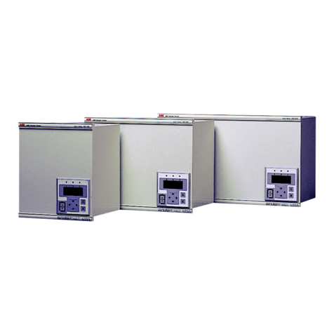
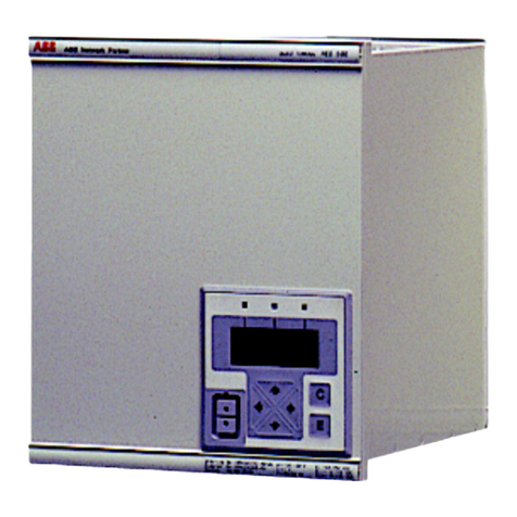
ABB REL 505-C1 2.3 Series Guide

© ABB Automation Products AB 2001
Substation Automation Division
Installation and commissioning manual
REL 505-C1*2.3
Overcurrent protection terminal
About this manual
DocID: 1MRK 506 094-UEN
Issue date: June 2001
Status: New
Version: 2.3
Revision: 00

COPYRIGHT
WE RESERVE ALL RIGHTS TO THIS DOCUMENT, EVEN IN THE EVENT THAT A PATENT IS ISSUED AND A DIFFERENT
COMMERCIAL PROPRIETARY RIGHT IS REGISTERED. IMPROPER USE, IN PARTICULAR REPRODUCTION AND DIS-
SEMINATION TO THIRD PARTIES, IS NOT PERMITTED.
THIS DOCUMENT HAS BEEN CAREFULLY CHECKED. IF THE USER NEVERTHELESS DETECTS ANY ERRORS, HE IS
ASKED TO NOTIFY US AS SOON AS POSSIBLE.
THE DATA CONTAINED IN THIS MANUAL IS INTENDED SOLELY FOR THE PRODUCT DESCRIPTION AND IS NOT TO BE
DEEMED TO BE A STATEMENT OF GUARANTEED PROPERTIES. IN THE INTERESTS OF OUR CUSTOMERS, WE CON-
STANTLY SEEK TO ENSURE THAT OUR PRODUCTS ARE DEVELOPED TO THE LATEST TECHNOLOGICAL STAN-
DARDS. AS A RESULT, IT IS POSSIBLE THAT THERE MAY BE SOME DIFFERENCES BETWEEN THE HW/SW PRODUCT
AND THIS INFORMATION PRODUCT.
Manufacturer:
ABB Automation Products AB
Substation Automation Division
SE-721 59 Västerås
Sweden
Tel: +46 (0) 21 34 20 00
Fax: +46 (0) 21 14 69 18
Internet: http://www.abb.se

Contents
PageChapter
Chapter 1 Introduction..................................................................... 1
Introduction to the installation and commissioning manual ................. 2
About the complete set of manuals to a terminal............................ 2
About the installation and commissioning manual.......................... 3
Intended audience.......................................................................... 3
Related documents......................................................................... 4
Revision notes................................................................................ 4
Chapter 2 Safety information........................................................... 5
Warning signs...................................................................................... 6
Caution signs....................................................................................... 8
Note signs............................................................................................ 9
Chapter 3 Overview ........................................................................ 11
Commissioning and installation overview.......................................... 12
Chapter 4 Unpacking and checking the terminal ........................ 13
Receiving, unpacking and checking .................................................. 14
Chapter 5 Installing the terminal................................................... 15
Overview............................................................................................ 16
Mounting the terminal........................................................................ 17
Mounting in a 19-inch rack ........................................................... 18
Mounting in a 19-inch rack with an additional box type RHGS..... 19
Mounting in a flush or semi-flush installation................................ 21
Mounting on a wall ....................................................................... 24
Making the electrical connections...................................................... 26
Connecting the CT circuits............................................................ 26
Connecting the auxiliary power, VT and signal connectors.......... 26
Connecting to protective ground................................................... 27
Making the screen connection...................................................... 27
Installing the optical fibres ................................................................. 28
Chapter 6 Checking the external circuitry.................................... 29
Overview............................................................................................ 30

Contents
Checking the CT and VT circuits ....................................................... 31
Checking the power supply................................................................ 32
Checking the binary I/O circuits......................................................... 33
Binary input circuits....................................................................... 33
Binary output circuits .................................................................... 33
Chapter 7 Energising the terminal.................................................35
Overview............................................................................................ 36
Energising the terminal...................................................................... 37
Checking the self supervision signals................................................ 38
Reconfiguring the terminal............................................................ 38
Setting the terminal time............................................................... 38
Checking the self supervision function ......................................... 39
Self supervision HMI data............................................................. 39
Chapter 8 Setting and configuring the terminal...........................41
Overview............................................................................................ 42
Entering settings through the local HMI............................................. 43
Downloading settings and configuration from a PC........................... 44
Establishing front port communication.......................................... 44
Establishing rear port communication........................................... 44
Downloading the configuration and setting files ........................... 46
Chapter 9 Establishing connection and verifying the SPA/IEC-
communication..............................................................47
Entering settings................................................................................ 48
Entering SPA settings................................................................... 48
Entering IEC settings.................................................................... 48
Verifying the communication.............................................................. 50
Verifying SPA communication ...................................................... 50
Verifying IEC communication........................................................ 50
Chapter 10 Verifying settings by secondary injection .................51
Overview............................................................................................ 52
Preparing for test ............................................................................... 54
Overview....................................................................................... 54
Preparing the connection to the test equipment ........................... 54
Setting the terminal in test mode .................................................. 55
Connecting test equipment to the terminal................................... 55
Verifying the connection and the analog inputs............................ 56
Releasing the function(s) to be tested.......................................... 57
Checking the disturbance report settings ..................................... 58

Contents
Current reversal and weak end infeed logic for
distance protection (ZCAL) .............................................................. 60
Current reversal logic.................................................................... 60
Weak end infeed logic .................................................................. 61
Completing the test....................................................................... 62
Current reversal and weak end infeed logic for residual
overcurrent protection (EFCA) ......................................................... 63
Testing the current reversal logic.................................................. 63
Testing the weak-end-infeed logic................................................ 63
Completing the test....................................................................... 65
Definite and inverse time-delayed residual
overcurrent protection (TEF) ............................................................. 66
Checking the operate values of the
current measuring elements ................................................. 66
Event function (EV)............................................................................ 70
Event recorder ................................................................................... 71
Fuse failure supervision (FUSE)........................................................ 72
Checking that the binary inputs and outputs
operate as expected .............................................................. 72
Measuring the operate value for the
negative sequence function .................................................. 73
Measuring the operate value for the zero sequence function....... 74
Checking the operation of the du/dt, di/dt based function ............ 75
Completing the test....................................................................... 76
High speed binary output logic (HSBO)............................................. 77
HSBO- trip from communication logic........................................... 77
HSBO- trip from the high-speed function (HS) ............................. 79
HSBO- trip from the distance protection zone 1 function (ZM1)... 80
Completing the test....................................................................... 81
Instantaneous overcurrent protection (IOC) ...................................... 82
Measuring the operate limit of set values..................................... 82
Completing the test....................................................................... 83
Monitoring of AC analogue measurements ....................................... 84
Monitoring of DC analogue measurements ....................................... 85
Setting lockout (HMI)......................................................................... 87
Scheme communication logic for distance protection
functions (ZCOM) ............................................................................ 88
Testing permissive underreach..................................................... 88
Testing permissive overreach....................................................... 89
Testing blocking scheme.............................................................. 89
Checking of unblocking logic........................................................ 90
Completing the test....................................................................... 90
Scheme communication logic for residual
overcurrent protection (EFC) ........................................................... 91
Testing the directional comparison logic function......................... 91
Completing the test....................................................................... 92
Setting group selector (GRP)............................................................. 93
Time delayed overcurrent protection (TOC)...................................... 94
Measuring the operate limit of set values..................................... 94
Completing the test....................................................................... 95
Trip logic (TR).................................................................................... 96
3ph operating mode...................................................................... 96
1ph/3ph operating mode............................................................... 96
Contents
1ph/2ph/3ph operating mode........................................................ 97
Completing the test....................................................................... 98
Two step time delayed directional phase
overcurrent protection (TOC3) .......................................................... 99
Measuring the operate and time limit for set values..................... 99
Completing the test..................................................................... 101
Two step time delayed phase overcurrent protection (TOC2)......... 102
Measuring the operate and time limit for set values................... 102
Completing the test..................................................................... 103
Chapter 11 Verifying the internal configuration...........................105
Overview.......................................................................................... 106
Testing the interaction of the distance protection ............................ 107
Chapter 12 Testing the protection system ...................................109
Overview.......................................................................................... 110
Testing the interaction of the distance protection ............................ 111

1
About this chapter Chapter 1
Introduction
Chapter 1 Introduction
About this chapter
This chapter introduces the user to the manual as such.

2
Introduction to the installation and
commissioning manual Chapter 1
Introduction
1 Introductiontotheinstallationandcommissioning
manual
1.1 About the complete set of manuals to a terminal
The complete package of manuals to a terminal is named users manual (UM). The Us-
ers manual consists of four different manuals:
The Application Manual (AM) contains descriptions, such as application and func-
tionality descriptions as well as setting calculation examples sorted per function. The
application manual should be used when designing and engineering the protection ter-
minal to find out where and for what a typical protection function could be used. The
manual should also be used when calculating settings and creating configurations.
The Technical Reference Manual (TRM) contains technical descriptions, such as
function blocks, logic diagrams, input and output signals, setting parameter tables and
technical data sorted per function. The technical reference manual should be used as a
technical reference during the engineering phase, installation and commissioning phase
and during the normal service phase.
The Operator´s Manual (OM) contains instructions on how to operate the protection
terminal during normal service (after commissioning and before periodic maintenance
tests). The operator´s manual could be used to find out how to handle disturbances or
how to view calculated and measured network data in order to determine the reason of
a fault.
The Installation and Commissioning Manual (ICM) contains instructions on how to
install and commission the protection terminal. The manual can also be used as a refer-
ence if a periodic test is performed. The manual covers procedures for mechanical and
electrical installation, energising and checking of external circuitry, setting and config-
uration as well as verifying settings and performing a directionality test. The chapters
and sections are organised in the chronological order (indicated by chapter/section
numbers) the protection terminal should be installed and commissioned.
Application
manual Technical
reference
manual
Installation and
commissioning
manual
Operator´s
manual
en01000044.vsd

3
Introduction to the installation and
commissioning manual Chapter 1
Introduction
1.2 About the installation and commissioning manual
The installation and commissioning manual contains the following chapters:
•Thechapter“Safety information” presents warning and note signs, which the user
should draw attention to.
• The chapter “Overview” gives an overview over the major task when installing and
commissioning the terminal.
•Thechapter“Unpacking and checking the terminal” contains instructions on how
to receive the terminal.
•Thechapter“Installing the terminal” contains instructions on how to install the ter-
minal.
• Thechapter “Checkingtheexternalcircuitry”containsinstructionsonhowto check
that the terminal is properly connected to the protection system.
• The chapter “Energising the terminal” contains instructions on how to start-up the
terminal.
•Thechapter“Configuring the digital communication modules” contains instruc-
tions on how to configure the communication modules such as modems, optical con-
verters etc if included in the terminal.
• The chapter “Setting and configuring the terminal” contains instructions on how to
download settings and configuration to the terminal.
• The chapter “Establishing connection and verifying the SPA/IEC-communication”
contains instructions on how to enter SPA/IEC settings and verifying the SPA/IEC
communication.
•Thechapter“Verifying settings by secondary injection” contains instructions on
how to verify that each included function operates correctly according to the set val-
ue.
•Thechapter“Verifying the internal configuration” contains instructions on how
verify that the terminal is properly configured.
• The chapter “Testing the protection system” contains instructionson how to test that
the terminal is in contact with the primary system.
•Thechapter“Checking the directionality” contains instructions on how to test di-
rectional dependent functions, if included in the terminal.
1.3 Intended audience
1.3.1 General
The installation and commissioning manual is addressing the installation, commission-
ing andmaintenance personnel responsiblefor taking theprotection intonormalservice
and out of service.

4
Introduction to the installation and
commissioning manual Chapter 1
Introduction
1.3.2 Requirements
The installation personnel must have a basic knowledge in handling electronic equip-
ment. The commissioning and maintenance personnel must be well experienced in us-
ing protection equipment, test equipment, protection functions and the configured
functional logics in the protection.
1.4 Related documents
1.5 Revision notes
Documents related to REL 505-C1*2.3 Identity number
Operator’s manual 1MRK 506 092-UEN
Installation and commissioning manual 1MRK 506 094-UEN
Technical reference manual 1MRK 506 093-UEN
Application manual 1MRK 506 115-UEN
Technical overview brochure 1MRK 506 091-BEN
Revision Description
2.3-00 First revision

5
About this chapter Chapter 2
Safety information
Chapter 2 Safety information
About this chapter
This chapter contains safety information. Warning signs are presented which attend the
user to be careful during certain operations in order to avoid human injuries or damage
to equipment

6
Warning signs Chapter 2
Safety information
1 Warning signs
Warning!
Strictly follow the company and country safety regulations. Working in a high voltage
environment requires serious approach to avoid human injuries and damage to equip-
ment.
Warning!
Do not touch circuitry during operation. Potentially lethal voltages and currents are
present.
Warning!
Always avoid to touch the circuitry when the cover is removed. The product contains
electronic circuitries which can be damaged if exposed to static electricity (ESD). The
electronic circuitries also contain high voltage which is lethal to humans.
Warning!
Always use suitable isolated test pins when measuring signals in open circuitry. Poten-
tially lethal voltages and currents are present.
Warning!
Never connect or disconnect a wire and/or a connector to or from a terminal during
normal operation. Hazardous voltages and currents are present that may be lethal. Op-
eration may be disrupted and terminal and measuring circuitry may be damaged.
Warning!
Always connect the terminal to protective ground, regardless of the operating condi-
tions. This also applies to special occasions such as bench testing, demonstrations and
off-site configuration. Operating the terminal without proper grounding may damage
both terminal and measuring circuitry, and may cause injuries in case of an accident.

7
Warning signs Chapter 2
Safety information
Warning!
Never disconnect a secondary connection of current transformer circuit without short-
circuiting the transformer’s secondary winding. Operating a current transformer with
the secondary winding open will cause a massive potential build-up that may damage
the transformer and may cause injuries to humans.
Warning!
Never unmount the front or back cover from a powered terminal or from a terminal con-
nected to powered circuitry. Potentially lethal voltages and currents are present.

8
Caution signs Chapter 2
Safety information
2 Caution signs
Caution!
Always transport modules using certified conductive bags. Always handle modules us-
ing a conductive wrist strap connected to protective ground and on a suitable antistatic
surface. Electrostatic discharge (ESD) may cause damage to the module.
Caution!
Do not connect live wires to the terminal. Internal circuitry may be damaged
Caution!
Always use a conductive wrist strap connected to protective ground when replacing
modules. Electrostatic discharge (ESD) may damage the module and terminal circuit-
ry.
Caution!
Take care to avoid electrical shock if accessing wiring and connection terminals when
installing and commissioning.

9
Note signs Chapter 2
Safety information
3 Note signs
Note!
Changing the active setting group will inevitably change the terminal’s operation. Be
careful and check regulations before making the change.
Note!
The protection assembly is designed for a maximum continuous current of four times
rated value.
Note!
Activating the setting lockout function, which prevents unauthorised changes of the set-
tings, without proper configuration may seriously affect the terminal’s operation.

10
Note signs Chapter 2
Safety information

11
About this chapter Chapter 3
Overview
Chapter 3 Overview
About this chapter
This chapter introduces the user to the installation and commissioning tasks.

12
Commissioning and installation overview Chapter 3
Overview
1 Commissioning and installation overview
The settings for each function must be calculated before the commissioning task can
start. A configuration, made in the configuration and programming tool, must also be
available if the terminal does not have a factory configuration downloaded.
The terminal is unpacked and visually checked. It is preferably mounted in a cubicle or
on a wall. The connection to the protection system has to be checked in order to verify
that the installation was successful.
The installation and commissioning task starts with configuring thedigital communica-
tion modules, if included. The terminal can then be configured and set, which means
that settingsand a configuration has to be appliedif the terminal does not have a factory
configuration downloaded. Then the operation of each included function according to
applied settings has to be verified by secondary injection. A complete check of the con-
figuration can then be made. A conformity test of the secondary system has also to be
done. When the primary system has been energised a directionality check should be
made.

13
About this chapter Chapter 4
Unpacking and checking the
terminal
Chapter 4 Unpacking and
checking the
terminal
About this chapter
This chapter contains instructions on how to receive the terminal.

14
Receiving, unpacking and checking Chapter 4
Unpacking and checking the
terminal
1 Receiving, unpacking and checking
Procedure
1. Remove the transport casing.
2. Visually inspect the terminal.
3. Check that all items are included in accordance with the de-
livery documents.
The user is requested to check that all software functions are in-
cluded according to the delivery documents after the terminal has
been energised.
4. Check for transport damages.
In case of transport damage appropriate action must be taken
against the latest carrier and the nearest ABB office or representa-
tive should be informed. ABB should be notified immediately if
there are any discrepancies in relation to the delivery documents.
Store the terminal in the original transport casing in a dry and dust
free place, if the terminal is not to be installed or commissioned
immediately. Observe the environmental requirements stated in
the technical data.
Table of contents
Other ABB Touch Terminal manuals

ABB
ABB REO 517 Instructions for use

ABB
ABB RET 54 Series Use and care manual

ABB
ABB ETL600 User manual

ABB
ABB SPAC 531 C Parts list manual

ABB
ABB Unifix AD 1STQ004320B0000 manual

ABB
ABB SACE Tmax T7D/PV User manual

ABB
ABB Protect IT REL 501 2.5 Series User manual

ABB
ABB REF 54 Series Product manual

ABB
ABB SPAC 310 C Parts list manual

ABB
ABB REL 561*2.5 User manual

ABB
ABB SACE Tmax XT User manual

ABB
ABB REB 551-C3*2.5 Guide

ABB
ABB Welcome M25102 C Series User manual

ABB
ABB REF 54 Series Use and care manual

ABB
ABB REF 541 User manual

ABB
ABB CP410 User manual

ABB
ABB REF 54 Series User manual

ABB
ABB REC 561 User manual

ABB
ABB REL 551-C1*2.5 Product manual

ABB
ABB Symphony Harmony Series User manual