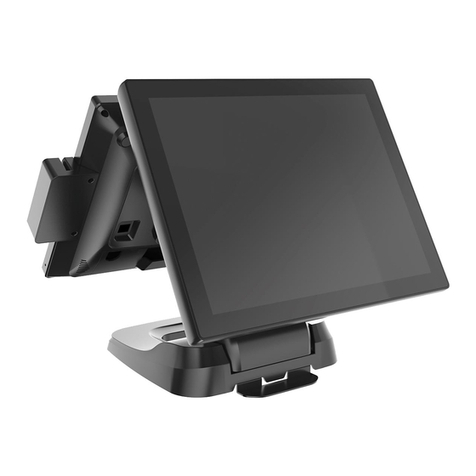
Hisense HK950 User manual

1
HK950 All-In-One POS
User Manual

2
Attention
☆Being in using process we must use three-hole socket and UPS power supply which accord with national level of CCC
certification, ground wire must be connected correctly, the supply voltage must be stable, confirm the socket provides the
voltage to correspond to voltages of the machine.
☆Do not sprinkle any liquid or drop into any object.
☆Do not press heavily, move it vigorously, shake or pound the machine.
☆Do not switch the power supply frequently, which can easily damage the machine.
☆Do not unplug any parts and peripherals of the machine under the working state, make sure the wire cables between
different parts of the machine fasten firmly.
☆The machine must be used with qualified printers and paper.
☆Do not extend the cable, replace the parts, please contact company or agent if there is any requirement.
☆The machine should work in a dry, ventilated, clean, without sunlit environment.
☆Avoid blocking or covering the main vent of the machine, must have an opening air outlet.
☆If you accidentally spill the liquid or drop into the sundries, please immediately turn off the machine and cut off the power,
remove the battery, dry the liquid or remove the sundries. If you remove the battery, you should reset the CMOS.
☆If there is a safety failure, such as peculiar smell, abnormal sound, leakage of electricity, etc., cut off the power supply
immediately and contact the after-sales service or agent of our company.
☆The interface is RJ50 serial port, COM2, COM3, COM4 with 12V power supply, please do not connect other equipments
to avoid damage the machine.
☆When inserting external U disk or other disks, kill virus firstly to avoid the host being infected by virus.
☆The rear RJ11 interface of the host is connected to the cash drawer, non-communication port, and users cannot use this
port for dial-up the Internet.
☆The product is A-level product, which may cause radio interference in the living environment. In this situation, it may be
necessary for the users to take action against it.
☆When the cash register is not used, we should turn off the machine and cut off the power then cover the dust cover.
☆Manufacturer has the right to modify the content of the specification without making a prior statement!
Warning:
1. Static electricity may damage the integrated circuit of the machine
2. If the battery is replaced improperly, it may cause explosion or serious damage.
It must be replaced with the same type of battery or battery recommended by
the manufacturer

3
Contents
HK950 ALL-IN-ONE POS............................................................................... 1
USER MANUAL............................................................................................. 1
ATTENTION .................................................................................................. 2
PRODUCTS DETAILS ................................................................................... 4
1. PACKAGING LIST ........................................................................................... 4
2. SPECIFICATION ............................................................................................. 4
3. COMPLETE DEVICE VIEW ............................................................................... 4
4. SIZE AND ROTATION ANGLE OF COMPLETE DEVICE........................................... 6
5. CONNECTORS PANEL .................................................................................... 7
6. DISASSEMBLE GUIDE OF DEVICE ..................................................................... 7
6.1 Disassemble Base Rear shell................................................................ 7
6.2 Disassemble HDD ................................................................................. 7
6.3 Disassemble MSR:............................................................................. 8
6.4 Disassemble VFD.................................................................................. 8
6.5 Disassemble 15 inch second screen ..................................................... 9
7. MAINBOARD LAYOUT ..................................................................................... 9
8. CASH DRAWER ........................................................................................... 10

4
Products Details
1. Packaging list
a
POS device
b
Power adapter
c
Power line
d
Driver CD
e
User Manual
2. Specification
Item
description
System
CPU
Intel® Celeron® processor 3855U( Skylake )SOC
1.6Ghz,Dual-core dual-threaded ,Power consumption 15W
Intel® Celeron® processor 3955U( Skylake )
SOC 2.0Ghz,Dual-core dual-threaded ,Power consumption 15W
Intel® Core® processor i3-6100U( Skylake )
SOC 2.3Ghz,Dual-core Qual-threaded , Power consumption
15W
RAM
DDR4 4G (Up to 8G or more)
LCD + Touch
Panel
LCD size
15 inch
Brightness
300cd/m²
Resolution
1024×768
Touch Panel
5-wire true flat resistive touch panel(single touch, optional)
Capacitive Touch Panel
Storage
Hard disk
HDD SATA 2.5 inch (500GB Standard)
SATA 64 GB SSD (larger capacity optional)
Ports
Serial Port
4* RJ50 serial ports; (COM2, COM3, COM4 5V/12V, COM4 is
suggested to connect VFD, voltage can be modified in BIOS.)
USB Port
4* USB 2.0 (2 Side,2Rear),2*USB3.0
VGA Port
1 * VGA
LAN Port
1 * RJ-45 (1000Mbps Gigabit LAN)
Audio Port
1 Line-out
Cash Drawer Port
1 * RJ-11 24V
DC 12V out
1
Power
AC External Power
DC 24V,2.5A
DC 24V 3.75A
Peripherals
MSR card reader
3 Tracks (USB)
Fingerprint
USB type Fingerprint module
RFID
RFID Reader (USB, option)
VFD
2*20 characters VFD
Environment
Working Environment
5℃- 40℃
Working humidity
40% - 90%
3. Complete Device view

5
HK950 with 15 inch Second Screen
HK950 with VFD

6
4. Size and Rotation angle of Complete Device.
HK950 with single Screen
Host 0 °~45 °
adjustable
Second screen 0°~30°adjustable
360mm
405mm

7
5. Connectors Panel
6. Disassemble guide of Device
6.1 Disassemble Base Rear shell
Step 1:follow the arrow direction to rotate the lock to" "position;
Step 2:Hold the rear shell with both hands and remove it.
6.2 Disassemble HDD
Step 1:Press the 2 buckle position and lift upwards the cable cover to open it.
Step 2:Pinch the hard drive with your thumb and index finger as picture shows, and then pull out
the hard drive as arrow direction.

8
6.3 Disassemble MSR:
Step 1:unplug the USB connector;
Step 2:press the release button as picture shows , hold the MSR shell and remove it as
arrow direction(upwards);
6.4 Disassemble VFD
Step 1:Open the cable cover as 6.2 step 1, unplug the VFD cable connector (host side),then
remove the rear shell of base as 6.1shows,
Step 2:Unscrew the 3 screws which fixing the VFD hinge bracket, hold the VFD and move
upwards to remove it.(VFD cable goes through base holes gently to avoid damage);

9
6.5 Disassemble 15 inch second screen
Step 1:Open the cable cover as 6.2 step 1, unplug the second screen cables connectors (host
side),then remove the rear shell of base as 6.1shows,;
Step 2:Unscrew the 3 screws which fixing the second screen hinge bracket, hold the second
screen shell and move upwards to remove it.(second screen cables go through base holes gently
to avoid damage);
7. Mainboard Layout

10
Mainboard pins
connectors
Pins specification
1.COM4
Serial port connector
Serial port 4(voltage 5V/12V)
For VFD
2.COM3
Serial port connector
Serial port 3(voltage 5V/12V)
3.COM2
Serial port connector
Serial port 2(voltage 5V/12V)
4.COM1
Serial port connector
Serial port 1
5.R_USB3
USB connector
Rear double layer USB 2.0 port
6.R_USB1
USB connector
Rear double layer USB 3.0 port
7.HDMI1
HDMI connector
Rear HDMI port
8.VGA1
VGA connector
Rear VGA port
9.CASH1
RJ11 connector
RJ11port, for +24Vcash drawer
10.DC_IN1
DC 24V power connector
System Power input port
11.DC_OUT1
DC 12V power output
12V power output port
12.RJ45_1
LAN connector
LAN network port
13.JACK1
Headphone connector
Earphone port
14.R_USB2
USB connector
Rear double layer USB 2.0 port
15.BAT1
CMOS Battery
Mainboard CMOS battery
16.J_LPT1
LPT connector
Parallel Printer port
17.F_PANEL1
Front Panel connector
Switch board port
18.J_SPK1
1*4Pin 2.0mm wafer box
Onboard Speaker output port
19.TOUCH1
Resistive touch connector
Resistive touch panel port
20.F_USB3
USB header
Onboard USB port
21. DIMM1
1*260pin SO-DIMM Socket
DDR4 RAM port
22. F_USB2
USB header
Onboard USB port
23.J_COM6
Serial port header
Onboard serial port 6
24.F_USB4
USB header
Onboard USB port
25. J_COM6
Serial port header
Onboard serial port 5
26.SIM1
MINIPCIE
SIM card
27.MINI_PCIE1
MINIPCIE
Wireless network card
28.MINI_PCIE2
Mini SATA
MSATA harddisk port
29.LVDS_P1
LVDS Inverter power connector
LVDS power port
30.CPU_FAN1
FAN connector
Smart fan port
31.J_DEG1
Debug
Debug port
32.P_SATA1
Serial Advanced Technology Attachment
Power Connector
SATA power cable port
33.S_ATA1
Serial Advanced Technology Attachment
Connector
SATA signal cable port
34.LVDS1
Low Voltage Differential Signaling
Transmitter Interface
LVDS port
8. Cash Drawer
/*
This Demo program for POS box
CD_SENSE GP23
CD_OPEN GP36

11
*/
#include "stdio.h"
#include "conio.h"
#include "graphics.h"
#include "string.h"
#include "io.h"
#define BIT0 0x01
#define BIT1 0x02
#define BIT2 0x04
#define BIT3 0x08
#define BIT4 0x10
#define BIT5 0x20
#define BIT6 0x40
#define BIT7 0x80
#define IO_Base 0xA00
#define CDS_PORT IO_Base+4
#define CDO_PORT IO_Base+3
void Init_DIO_Default()
{
}
/*-----------------------------------------------
@brief : Set CD_OPEN power level
@Input : Level-- 0:Low 1: High
------------------------------------------------*/
void Set_CD_OPEN(int Level)
{ int t;
if(Level)
{ outportb(CDO_PORT,inportb(CDO_PORT)|BIT0);
printf(" CD_OPEN is High \n");
}
else
{ outportb(CDO_PORT,inportb(CDO_PORT) &~BIT0);
printf("CD_OPEN is Low\n");
}
}
/*-----------------------------------------------
@brief : Get CD_SENSE low active
@Return : 1:Low active with no jitter
------------------------------------------------*/
int Get_CD_SENSE_Status()

12
{
if(inportb(CDS_PORT)&BIT3)
{ delay(100);
if(inportb(CDS_PORT)&BIT3)
{
printf("CD_SENSE is Low level stability.\n");
return 1;
}
}
else
printf("CD_SENSE is High level\n");
return 0;
}
main()
{
printf("System ready\n ");
/*Set_CD_OPEN High */
Set_CD_OPEN(1);
/*Set_CD_OPEN Low */
Set_CD_OPEN(0);
while(1)
{
Get_CD_SENSE_Status();
}
}
Other manuals for HK950
1
Table of contents
Other Hisense Touch Terminal manuals

Hisense
Hisense HK570 User manual

Hisense
Hisense HK800 SERIES User manual

Hisense
Hisense HK716 Series Quick setup guide

Hisense
Hisense HK950 User manual

Hisense
Hisense HM626R User manual

Hisense
Hisense HK316 User manual

Hisense
Hisense HK560M User manual

Hisense
Hisense HK560 User manual

Hisense
Hisense HK870 Series Quick setup guide

Hisense
Hisense HM518 User manual