Abbriata Miniroto M50 User manual

www.tractortoolsdirect.com
(260)BALE-HAY

Abbriata M50 Quick Start Guide
Contents
Scope and Purpose.............................................................................................................................................. 3
Cutting the driveline to fit your tractor............................................................................................................... 3
Read the owner’s manual.................................................................................................................................... 3
Unloading from the truck.................................................................................................................................... 3
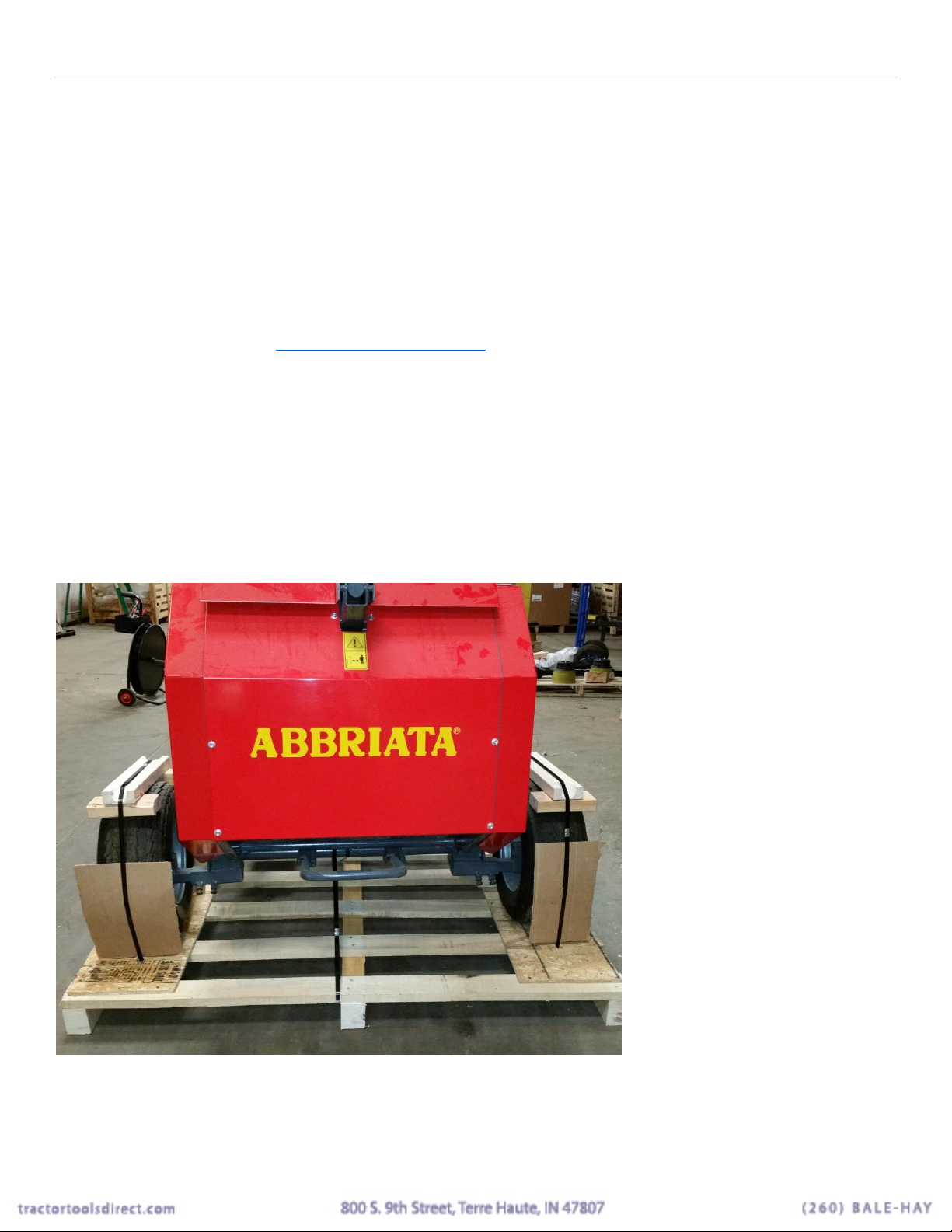
Removing Center Draw type from pallet............................................................................................................ 3
Hitch pin for pintle hitch................................................................................................................................. 6
Remove boards from pallet............................................................................................................................. 7
Measure tractor hitch height ............................................................................................................................... 9
Setting hitch height........................................................................................................................................... 10
Gathering wheels .............................................................................................................................................. 11
Pickup height setting......................................................................................................................................... 12
Gauge wheel...................................................................................................................................................... 13
Height verification............................................................................................................................................ 13
Bale sensor and siren ........................................................................................................................................ 14
Bale density....................................................................................................................................................... 14
Shear pin ........................................................................................................................................................... 15
Bag of spares..................................................................................................................................................... 15
Bale ejector plates............................................................................................................................................. 16
Lift points.......................................................................................................................................................... 17
Oil the chains .................................................................................................................................................... 17
Door speed control............................................................................................................................................ 18
Figure 1 fork form this side if possible................................................................................................................... 3
Figure 2 center draw type are attached to the pallet with the draw bar folded up for shipping.............................. 4
Figure 3 leave the steel strapping in place.............................................................................................................. 4
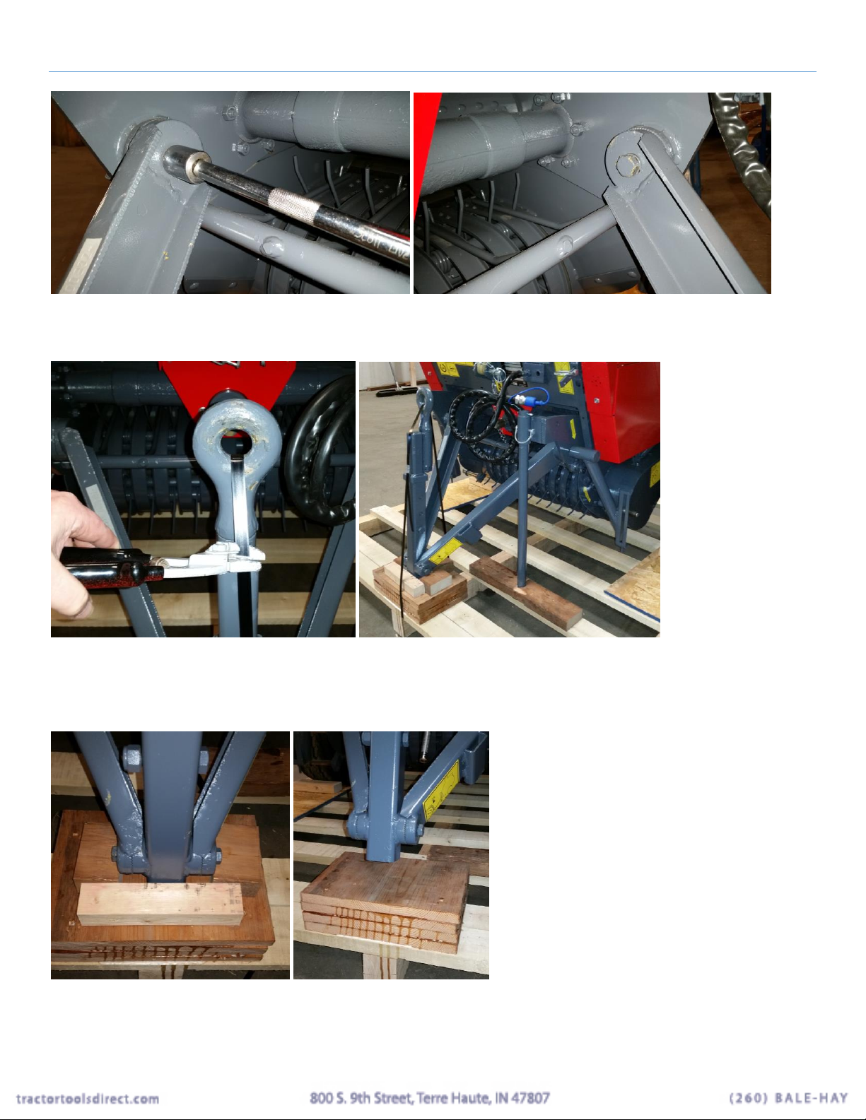
Figure 4 bolts that hold drawbar angle adjustment use 24 mm socket................................................................... 5
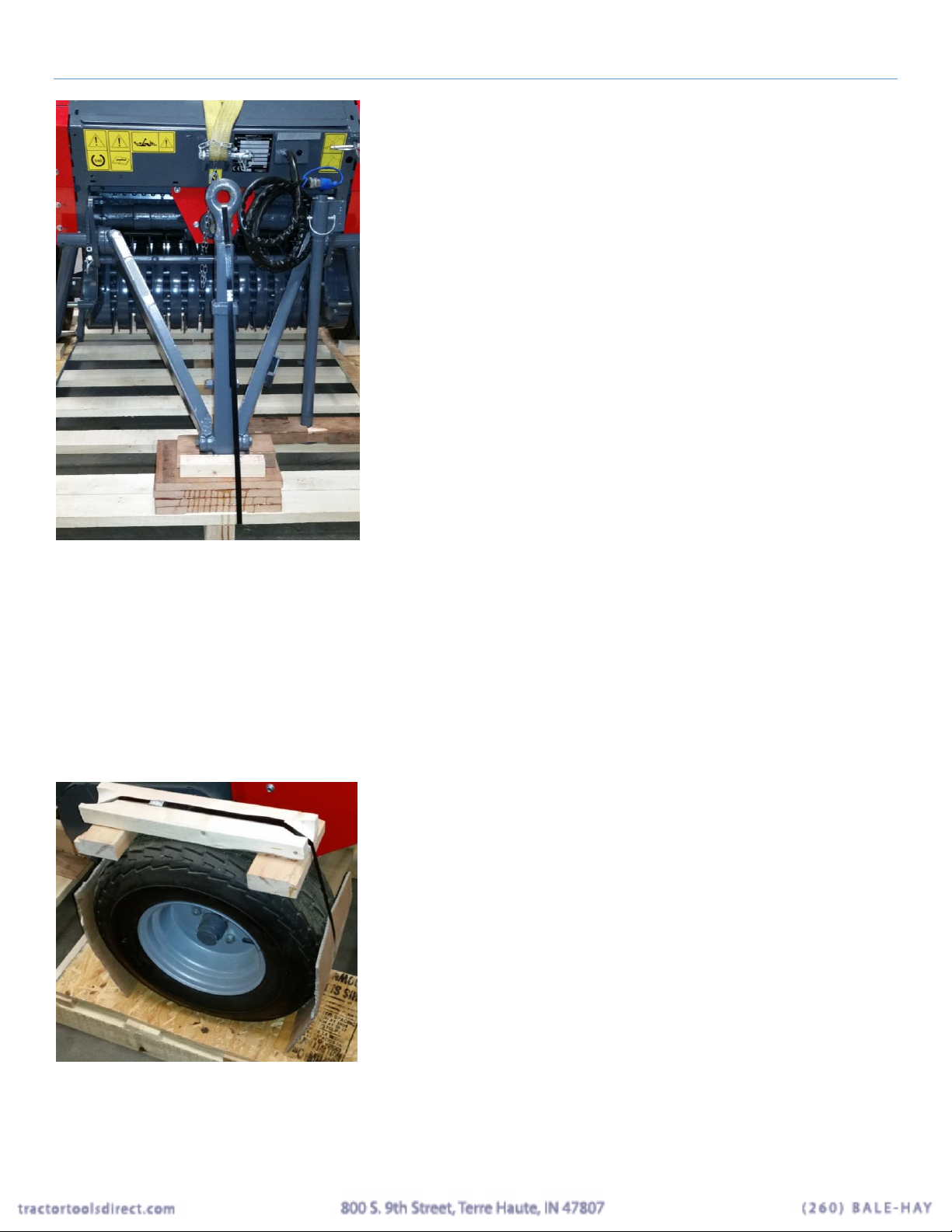
Figure 5 cut steel strap holding the draw bar down............................................................................................... 5
Figure 6 raising up the drawbar.............................................................................................................................. 5
Figure 7 draw bar folded down.............................................................................................................................. 6
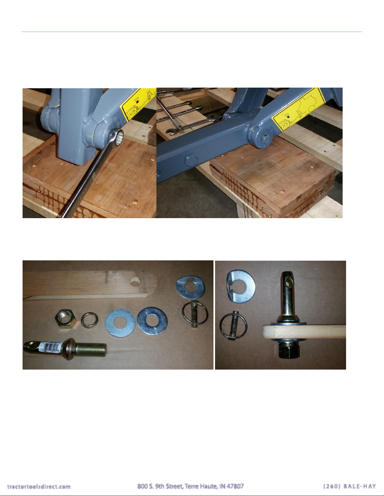
Figure 8 hitch pin parts assembled......................................................................................................................... 6
Figure 9 hitch to baler............................................................................................................................................ 7
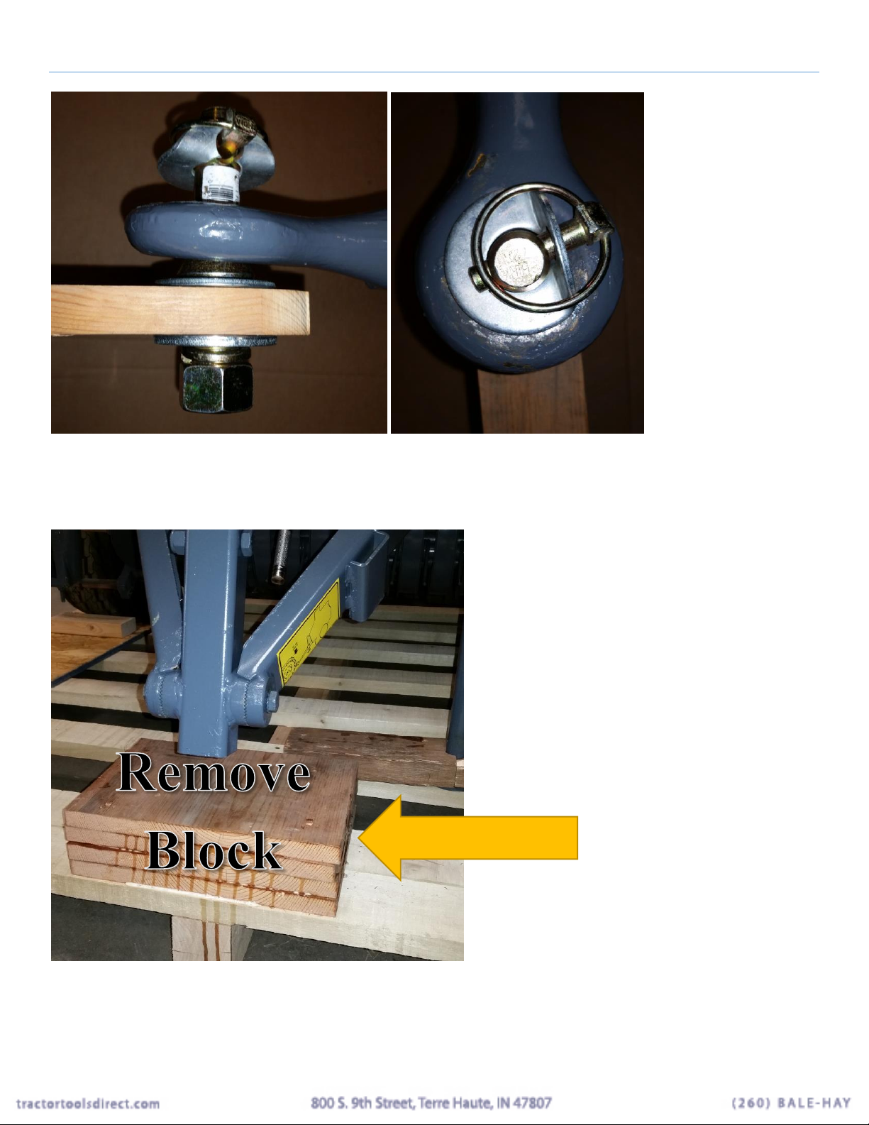
Figure 10 remove block in center .......................................................................................................................... 7
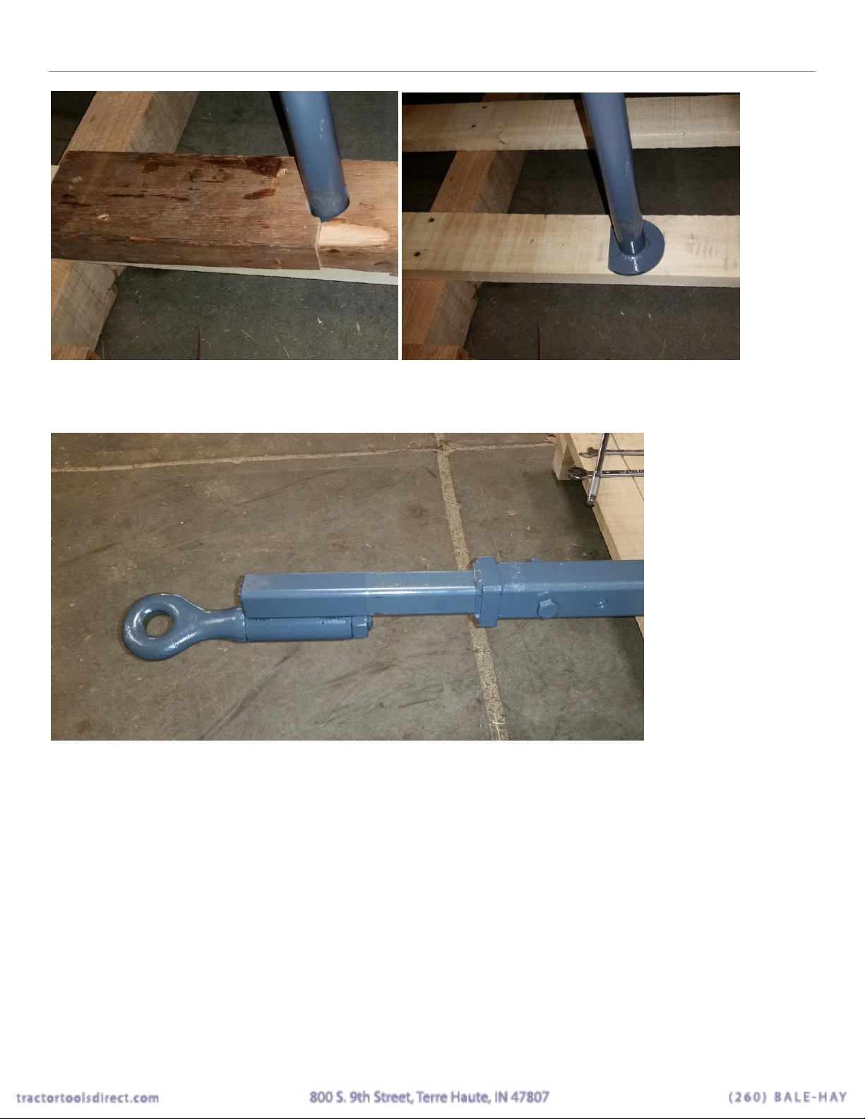
Figure 11 remove boards from jack stand.............................................................................................................. 8

Abbriata M50 Quick Start Guide Copyright 2015 Tractor Tools Direct
Page | 2
Figure 12 draw bar to attach to tractor................................................................................................................... 8
Figure 13 remove pin and raise jack....................................................................................................................... 9
Figure 14 pickup tines in raised position............................................................................................................... 9
Figure 15 set height of pintle hitch...................................................................................................................... 10
Figure 16 point to jack up baler........................................................................................................................... 11
Figure 17 gathering wheel orientation................................................................................................................. 11
Figure 18 gathering wheels are installed as shown.............................................................................................. 12
Figure 19 pickup height handle and pin shown in transport position.................................................................. 12
Figure 20 pickup in down position ....................................................................................................................... 13
Figure 21 gauge wheel shown in stored position and the bale position................................................................ 13
Figure 22 location of siren switch and battery..................................................................................................... 14
Figure 23 testing the siren is on............................................................................................................................ 14
Figure 24 remove this cover to access bale density setting ................................................................................. 15
Figure 25 shear pin location................................................................................................................................. 15
Figure 26 bag of spare parts.................................................................................................................................. 16
Figure 27 bale ejector plate................................................................................................................................... 16
Figure 28 location for ejector plates ..................................................................................................................... 16
Figure 29 chain lube for the drive chains.............................................................................................................. 17
Figure 30 speed control for door........................................................................................................................... 18

Abbriata M50 Quick Start Guide Copyright 2015 Tractor Tools Direct
Page | 3
Scope and Purpose
This guide is limited to the Abbriata M50 mini round balers sold by Tractor Tools Direct. The guide covers
models manufactured in 2014 and forward.
This manual is only a guide to aid in the unpacking and assembly of the models listed above. Consult the
operations manual for instructions on usage, safety and maintenance.
Cutting the driveline to fit your tractor
We have a separate publication that gives instructions on how to cut the driveline should it be too long for your
tractor. It’s on our website at www.tractortoolsdirect.com. The driveline supplied with your implement also has
an owner’s manual that has instructions detailing this procedure.
Read the owner’s manual
This guide only covers assembly and preparation of the baler. Safety and operation is covered in the owner’s
manual.
Unloading from the truck
The baler is on a wooden pallet. The weigh is mostly over the wheels. It is best to fork the unit so that the forks
are going in from the back. Have the forks as wide as possible. Place the pallet on level ground so that it does
not present a hazard when released from the pallet.
Figure 1 fork form this side if possible
Removing Center Draw type from pallet
As there are three types of hitch configuration, specific instructions will be given for each.

Abbriata M50 Quick Start Guide Copyright 2015 Tractor Tools Direct
Page | 4
Figure 2 center draw type are attached to the pallet with the draw bar folded up for shipping
The tools needed for this operation are as follows:
1. 24 mm socket (15/16 will substitute)
2. 22 mm wrenches, or adjustable (7/8 will substitute)
3. 19 mm wrench or socket (3/4 will substitute)
4. Crowbar or wrecking bar for removing nailed down wood
Do not cut the steel strapping around the wheels until directed to do so. The strapping will hold the unit in place
for your safety.
Figure 3 leave the steel strapping in place
Using a 24 mm socket (15/16 sub.) loosen the bolt holding the angle adjustment in place on both sides. Do not
remove the bolt.

Abbriata M50 Quick Start Guide Copyright 2015 Tractor Tools Direct
Page | 5
Figure 4 bolts that hold drawbar angle adjustment use 24 mm socket
Figure 5 cut steel strap holding the draw bar down
Cut any strapping holding the draw bar down. Remove the wood around the drawbar if needed with a crowbar.
Then raise the drawbar up about 2-3 inches.
Figure 6 raising up the drawbar

Abbriata M50 Quick Start Guide Copyright 2015 Tractor Tools Direct
Page | 6
Tighten the bolts on the baler to keep the draw bar up. Be sure they are tight and the teeth are engaged, if loose
the baler will fall forward.
Using a 19 mm or ¾” wrench, loosen the bolts on both sides of the 2nd adjustment and fold down the draw bar.
Then tighten the bolts being sure the teeth are engaged and tight, if loose the baler will fall forward.
Figure 7 draw bar folded down
Hitch pin for pintle hitch
Prepare the hitch pin on your tractor draw bar.
Figure 8 hitch pin parts assembled
The board with a hole represents the draw bar on the tractor.
The hitch attaches to the baler like this.

Abbriata M50 Quick Start Guide Copyright 2015 Tractor Tools Direct
Page | 7
Figure 9 hitch to baler
Remove boards from pallet
Remove the stack up of boards that the draw bar was resting on.
Figure 10 remove block in center
Remove the boards form the jack stand.

Abbriata M50 Quick Start Guide Copyright 2015 Tractor Tools Direct
Page | 8
Figure 11 remove boards from jack stand
Attach the drawbar to the tractor.
Figure 12 draw bar to attach to tractor
To lift the draw bar, use a jack under the arm. Attach to the tractor as in figure 9 above.
Set the brakes on the tractor. Remove all steel strapping on the wheels and under the baler so it is free to move.
Be sure you have removed the blocks from the center of the pallet as in figure 10 above.
Remove the pin from the jack stand and raise the jack stand so it is out of the way.

Abbriata M50 Quick Start Guide Copyright 2015 Tractor Tools Direct
Page | 9
Figure 13 remove pin and raise jack
Figure 14 pickup tines in raised position
Check to be sure the pick tines are raised and locked in the up position.
Drive the baler off the pallet.
Measure tractor hitch height
Measure the height of the top of the center draw bar to the floor.

Abbriata M50 Quick Start Guide Copyright 2015 Tractor Tools Direct
Page | 10
Setting hitch height
Using the adjustment points on the draw arm of the baler, set the height of the bottom of the pintle hitch on the
baler to about 1” below the height of the top of the draw bar on the tractor. This will make it easier to remove
the pin in the jack stand and raise it as it will be just off the ground when resting on the tractor hitch.
Figure 15 set height of pintle hitch

Abbriata M50 Quick Start Guide Copyright 2015 Tractor Tools Direct
Page | 11
Figure 16 point to jack up baler
Raise the baler just enough to clear the pin on the tractor.
When the baler is attached to the tractor the bottom of the jack stand should be just off the ground to make
raising it easier.
Gathering wheels
The center draw and lateral draw balers have gathering wheels. They are installed so that the tines nearest to the
ground are pointed forward.
Figure 17 gathering wheel orientation

Abbriata M50 Quick Start Guide Copyright 2015 Tractor Tools Direct
Page | 12
Figure 18 gathering wheels are installed as shown
The gathering wheels are not attached during shipment as they would extend past the 64” square pallet. Install
as shown. Be sure the wheel clears the hardware.
Pickup height setting
The pickup tines and the gathering wheels are raised into the transport position and lowered into the bale
position with this handle.
Whenever the baler is being transported, the pickup should be raised to keep the tines safe. See figure 19 for the
raised position.
Figure 19 pickup height handle and pin shown in transport position

Abbriata M50 Quick Start Guide Copyright 2015 Tractor Tools Direct
Page | 13
Figure 20 pickup in down position
Gauge wheel
The baler uses a steel gauge wheel to keep the tines from going too low. It rides along the ground and causes the
pickup and gathering wheels to raise up and then go back down as you pass over a hump in the ground.
It is stored for transport on top of the baler and the moved to the bale position as shown.
Figure 21 gauge wheel shown in stored position and the bale position
Height verification
Now that the gathering wheels and the gauge wheel are installed, attach the PTO and run the machine with the
tractor at an idle. Keeping well clear of the machine, verify that the pickup tines are turning so that they clear
the floor by about 1”to 1-1/2”. If this is not the case make an adjustment to the angle of the draw bar on the
baler at one of the 2 places. Be sure the machine is supported during adjustment. Use the jack stand or a lift
point to keep the baler from falling forward during adjustment of the hitch angles.
Note that the gauge wheel will not allow the pickup tines closer than 20 mm (3/4”) once it contacts the floor.

Abbriata M50 Quick Start Guide Copyright 2015 Tractor Tools Direct
Page | 14
Bale sensor and siren
The baler signals that the bale has achieved its desired size and weight by sounding a siren. The siren is turned
off during shipping. To switch it on, flip the switch on the black box. The siren runs on a 9 volt battery. It is
inside the black box. If, needed remove the box, open and change the battery as needed.
Figure 22 location of siren switch and battery
To test the siren, open the cover on the other side and push up on the switch trip arm.
Figure 23 testing the siren is on
Bale density
The setting of how tightly the bales are compressed is controlled by what hole the arm is in. The hole on top
will produce the lightest bale, while the hole on the bottom will produce the heaviest. You may not be able to
use the heaviest setting with all materials. The heaviest setting (bottom hole) is likely to break a shear pin. Start
at the 2nd hole down from the top and go from there.

Abbriata M50 Quick Start Guide Copyright 2015 Tractor Tools Direct
Page | 15
Figure 24 remove this cover to access bale density setting
Shear pin
The baler is protected from overload damage by a shear pin that is designed to break at a designed torque. Use
only the correct type of bolt, a hardened bolt will not break and will cause damage. There are spares in a bag in
the net wrap compartment.
Figure 25 shear pin location
Bag of spares
There is an assortment of spare parts shipped with the baler. Shear pins are in there.

Abbriata M50 Quick Start Guide Copyright 2015 Tractor Tools Direct
Page | 16
Figure 26 bag of spare parts
Bale ejector plates
Should you experience difficulty with bales ejecting from the baler, there are 2 plates to install that are included
with the baler.
Figure 27 bale ejector plate
Figure 28 location for ejector plates

Abbriata M50 Quick Start Guide Copyright 2015 Tractor Tools Direct
Page | 17
Lift points
Should you need to lift the baler, there are two lift points on the rear and one on the front where the top link
attaches on 3 point lift models. Install the provided plates shown after removing the top guard plates to install
the rear lift plates.
Oil the chains
Before using the baler the chains need to be oiled. The baler does not ship with the chains lubricated for use.
Use a chain lubricant or a light oil that can penetrate to the inside of the roller chain. Various brands are
available at the automotive department at Wal-Mart and auto part stores. The one pictured below in figure 29 is
what we recommend, and it gives good results. Grease should not be used as it will not penetrate inside the
chain where the lubrication is needed most.
Figure 29 chain lube for the drive chains
The covers should be removed to get good access when cleaning the unit and oiling.
There are three main drive chains, and they each need to be oiled before and after each use of the bailer. There
is a drive chain under the guard that drives the pickup reel that should be oiled every 100 hours or each season.

Abbriata M50 Quick Start Guide Copyright 2015 Tractor Tools Direct
Page | 18
Door speed control
The rear door is raised and lowered by hydraulics. Be sure the valve is on. The valve can be closed a little to
allow the door to close more slowly. Shown on the open (fast) position.
Figure 30 speed control for door
Table of contents