Concoa Altos 2 User manual

ADI 0025-G
ALTOS 2™
System Monitor
INSTALLATION AND OPERATING INSTRUCTIONS
Carefully Read These Instructions Before Operating
Carefully Read These
Controls Corporation of America
1501 Harpers Road • Virginia Beach, VA 23454
Telephone 1-800-225-0473 or 757-422-8330 • Fax 757-422-3125
www.concoa.com
May 2018
Revision G

SAFETY
BASIC SAFETY PRECAUTIONS MUST BE FOLLOWED TO REDUCE THE RISK OF
FIRE, ELECTRICAL SHOCK OR INJURY.
While the Altos 2™ is dust and moisture resistant, it is NOT water-proof or
completely sealed. It should be installed where it will not be subjected to rain or
high concentrations of dust. Never pour or spray liquids directly onto the product.
Install the Altos 2™ where the ambient temperature range is between 0° F and
140° F.
THIS PRODUCT IS NOT INTENDED FOR USE IN EXPLOSIVE
ENVIRONMENTS.
DO NOT INSTALL THIS PRODUCT IN ANY HAZARDOUS ENVIRONMENT.
If product appears damaged in any way, do not use and request service from
CONCOA.
USER RESPONSIBILITY
Service to this product should only be performed by CONCOA or an authorized
CONCOA agent. Requests for service may be made through CONCOA CUSTOMER
SERVICE at 1-800-225-0473. Written requests may be made using CONCOA’s FAX
CONCOA accepts no responsibility for damage or injury if this product is modified in
any way.
CONCOA assumes/accepts no liability or responsibility for damage to individuals or
equipment that may occur when using this product

1
Index
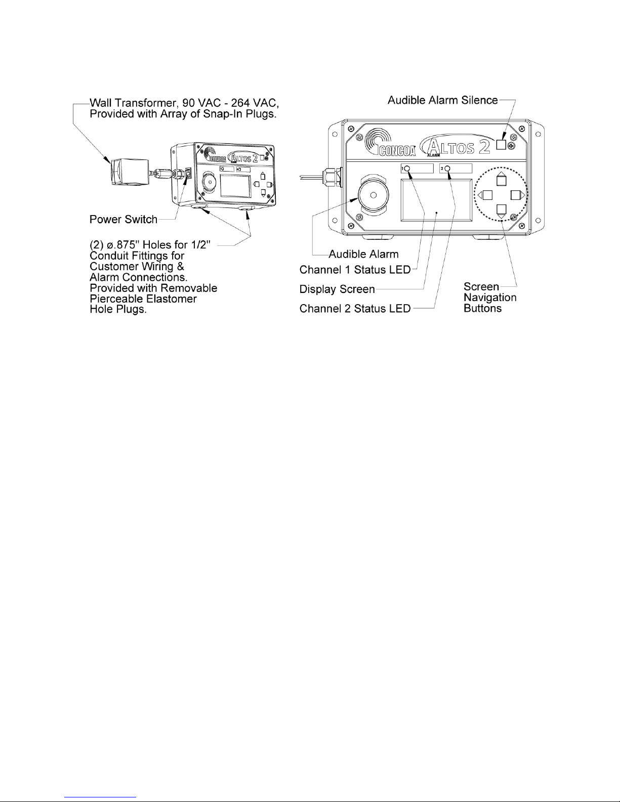
Description of Product.........................................................................................................2
Power Requirements............................................................................................................2
Alarm Relay Specifications .................................................................................................2
Understanding Alarm Operation..........................................................................................3
Mounting Requirements.......................................................................................................4
Installation Instructions........................................................................................................5
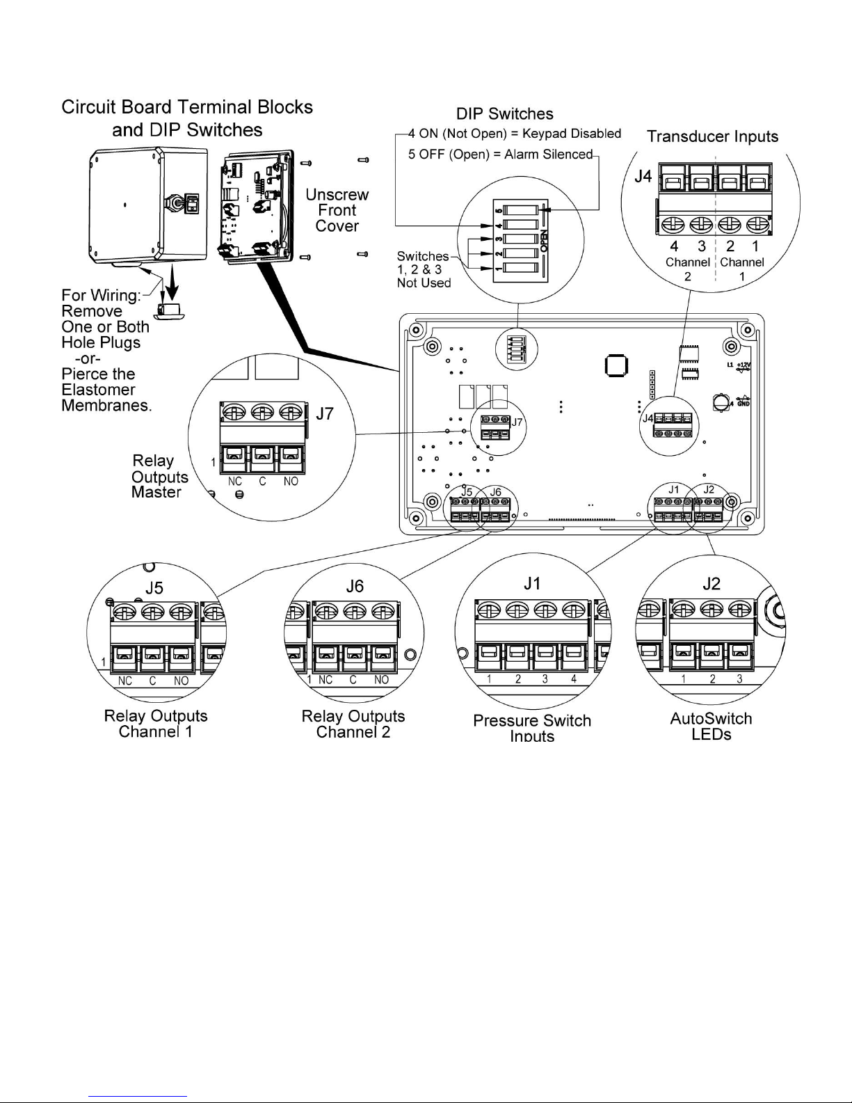
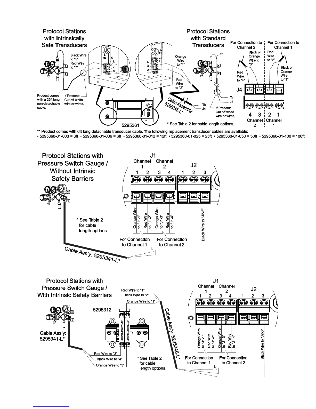
Connecting External Input Devices to the Altos 2™...........................................................5
Connecting Alarm Outputs................................................................................................16
Muting Audible Alarm.......................................................................................................16
Configuration using the LCD Screen.................................................................................17
Status Menu .......................................................................................................................18
Channel Settings ................................................................................................................19
Input/Alarm Mode .....................................................................................................20
Alarm Set Point..........................................................................................................21
Units of Measure........................................................................................................22
Alarm Settings ...................................................................................................................22
Alarm Delay...............................................................................................................23
Blink When Both In Alarm........................................................................................24
System Settings..................................................................................................................25
Set Channel Offset.....................................................................................................26
Set Channel Max........................................................................................................27
Deadband ...................................................................................................................28
Audible Mode ............................................................................................................29
Power Save Mode......................................................................................................30
Keypad Lockout.........................................................................................................31
Test Mode ..................................................................................................................31
Reset...........................................................................................................................32
About..........................................................................................................................32
Troubleshooting.................................................................................................................33
Warranty Information ........................................................................................................34

2
DESCRIPTION OF PRODUCT
The CONCOA Altos 2™ system monitor reports the status of up to 2 individual points of
observation. Ideal for monitoring automatic switchovers and other fail-safe gas delivery
installations with pressure switch or transducer pressure monitoring capability. The
pressure reading for 4-20mA transducers or contact closure status for pressure switches
will be displayed locally on a 2.57” LCD screen for up to 2 channels. The statuses of all
inputs are also displayed locally with high visibility multicolor LEDs that turn red when
an input exits its normal condition. Additionally, status may be accessed through three
dry contact relay outputs, one for each input channel and a master alarm.
POWER REQUIREMENTS
Input Voltage: External Power Supply
Universal input voltage 96-264 VAC, 50/60Hz.
Power Consumption: 5 watts
ALARM OUTPUT RELAY SPECIFICATIONS:
Contacts: Normally Open/ Normally Closed Dry Contact
Contact Rating: 24 volts DC @.5 amps Max.

3
UNDERSTANDING ALARM OPERATION
Figure 1
Figure 1 shows the location of the various inputs, outputs, and indicators for the Altos 2™. The
Altos 2™ has a universal power supply.
Input signals coming from external devices are connected to the Altos 2™ via individual wires
through a 1/2” conduit connection in the bottom of the enclosure to a terminal strip.
The Altos 2™ provides output relay signals to indicate the state of channel 1, 2, and the master
alarm. The master alarm is engaged when either channel is in alarm with signals brought out
through terminal connectors consisting of 3 terminal blocks. Each terminal block contains a
common voltage input, a normally-closed contact, and a normally-open contact.
Output relay signals are routed from the Altos 2™ terminal strip via individual wires through a
1/2” conduit connection on the bottom of the enclosure.
Figure 1 shows a view of the front panel which is laid out with two status lights representing
channels 1 and 2. The indicator lights are bi-colored LEDs so that the same light can be turned
ON as either a green indicator or a red indicator. A green LED indicates a normal condition. A
red LED indicates an alarm condition. If the option has been enabled, a blinking red LED
indicates that both channels are in alarm.
On the left side of the front panel, a speaker is used to provide an audible indication of an alarm
condition. The alarm silence button in the upper right portion of the front panel allows the
operator to silence the audible alarm even while an alarm condition still exists.
In the center of the front panel is a 2.9” diagonal LCD screen used for displaying channel 1 and 2
status as well as system configuration menus. On the right side of the screen are four directional
arrows used for navigating the configuration menu.
The Altos 2™ allows for either a 4-20mA transducer or a contact closure input (typical pressure
switch) for channel monitoring. The channel configuration is selectable via the system menu.

4
The 4-20mA inputs are accessed via a terminal block containing the +12vdc supply line and the
signal return for each channel. The channel pressure is displayed on the LCD screen and,
depending on the channel alarm configuration and set point, the channel LED with either be
green (normal state) or red (alarm state).
The contact closure inputs are also accessed via a terminal block containing a +12vdc supply line
and a signal return for each channel. The Altos 2™ can use normally closed (N.C.) or normally
open (N.O.) contact signals from the external inputs to determine the state of the alarms. The
normal conditions of these alarms are customizable via the configuration menu.
If there are no alarm conditions, the Altos 2™ will turn on the green indicator next to the status
being monitored. When an alarm condition occurs, the color of the indicator next to its status
changes from green to red. At the same time, the audible buzzer in the Altos 2™, if enabled, will
begin to sound. The LCD screen will display the current channel pressure or whether the contact
is open or closed depending on the channel’s configuration. The set of contacts representing this
alarm condition will alarm in the relay output section of the Altos 2™.
MOUNTING REQUIREMENTS
Figure 2

5
INSTALLATION INSTRUCTIONS
After mounting the Altos 2™ to the wall, wire any monitored devices through the conduit
connections and to the input terminal blocks (see Figures 3-13, Table 1). If using the relay
output of the Altos 2™ to connect to another alarm or system, attach wires to the relay output
terminal blocks (see Figure 3, Table 1).
Turn Altos 2™ on by plugging the unit directly into a wall outlet and turning the power switch
on the left side of the unit to the on position. The system may be tested once it is connected to an
external device by tripping the external alarm, causing the corresponding input LED to turn red.
CONNECTING EXTERNAL INPUT DEVICES TO THE
ALTOS 2™
The Altos 2™ is designed to interface with up to 2 external pressure transducers (by default) or
any dry contact inputs depending on the channel configuration. The external device wires
(+12Vdc out, signal in) are brought in through a conduit connector on the left side of the box and
connected to terminal blocks on the left hand side of the circuit board. Figures 3-13 and Table 1
outline how to connect various CONOCA products to the Altos 2™.
The recommended cable for this assembly is 14-26 AWG wire (Alpha # 1176C or equivalent).
The length of each cable should be limited to 500 feet for pressure transducers and 1500 feet for
dry contact inputs.
After cutting the cable to length, remove the outer jacket to expose approximately 3/4 inch of the
internal conductors on both sides of the cable. Strip away 1/4-inch of the insulation on each of
the conductors, unscrew the terminal block, insert wire, and tighten screw. Test to ensure the
wire does not pull out of the connector.
Table 2 shows common wire part numbers that are available to connect to various CONCOA
devices. Contact CONCOA for details.

6
Figure 3

7
Table 1
Terminal Function
J1-1 Channel 1 Pressure Switch Signal Return
J1-2 Channel 1 Pressure Switch +12V Supply
J1-3 Channel 2 Pressure Switch Signal Return
J1-4 Channel 2 Pressure Switch +12V Supply
Terminal Function
J4-1 Channel 1 Transducer Signal Return
J4-2 Channel 1 Transducer +12V Supply
J4-3 Channel 2 Transducer Signal Return
J4-4 Channel 2 Transducer +12V Supply
Terminal Function
J2-1 Channel 1 LED Driver (for 522/523 Switchovers Only)
J2-2 Channel 2 LED Driver (for 522/523 Switchovers Only)
J2-3 Ground
Terminal Function
J5-1 Channel 1 Normally Closed Relay Output
J5-2 Channel 1 Relay Common
J5-3 Channel 1 Normally Open Relay Output
Terminal Function
J6-1 Channel 2 Normally Closed Relay Output
J6-2 Channel 2 Relay Common
J6-3 Channel 2 Normally Open Relay Output
Terminal Function
J7-1 Master Normally Closed Relay Output
J7-2 Master Relay Common
J7-3 Master Normally Open Relay Output
Switch Function
SW1-5 Alarm Silence
SW1-4 Keypad Lockout
SW1-3 Reserved
SW1-2 Reserved
SW1-1 Reserved
Dipswitch
Input
Input
Output
Output
Output
Output

8
Figure 4
Figure 5
Figure 6

9
Figure 7

10
Figure 8
Figure 9

11
Figure 10

12
Figure 11

13
Figure 12
Figure 13

14
Figure 14
Figure 15

15
Table 2
Length Usage
5295320-3 3 Feet
5295320-10 10 Feet
5295320-25 25 Feet
5295320-50 50 Feet
5295320-100 100 Feet
5295340-3 3 Feet
5295340-10 10 Feet
5295340-25 25 Feet
5295340-50 50 Feet
5295340-100 100 Feet
5295341-3 3 Feet
5295341-10 10 Feet
5295341-25 25 Feet
5295341-50 50 Feet
5295341-100 100 Feet
5295342-3 3 Feet
5295342-10 10 Feet
5295342-25 25 Feet
5295342-50 50 Feet
5295342-100 100 Feet
5295343-3 3 Feet
5295343-10 10 Feet
5295343-25 25 Feet
5295343-50 50 Feet
5295343-100 100 Feet
5295344-3 3 Feet
5295344-10 10 Feet
5295344-25 25 Feet
5295344-50 50 Feet
5295344-100 100 Feet
5295345-3 3 Feet
5295345-10 10 Feet
5295345-25 25 Feet
5295345-50 50 Feet
5295345-100 100 Feet
5295346-3 3 Feet
5295346-10 10 Feet
5295346-25 25 Feet
5295346-50 50 Feet
5295346-100 100 Feet
5295350-3 3 Feet
5295350-10 10 Feet
5295350-25 25 Feet
5295350-50 50 Feet
5295350-100 100 Feet
5295360-01-003 3 Feet
5295360-01-006 6 Feet
5295360-01-012 12 Feet
5295360-01-025 25 Feet
5295360-01-050 50 Feet
5295360-01-100 100 Feet
*L in the Cable Assembly Part Number is the Length. Available Lengths are Shown in this Table.
542 Series High Flow Backup System
Protocol Stations with
Pressure Switch Gauge
AutoSwitches with
Pressure Switch Gauges
Dual Regulator Switchovers with Pressure
Switch Gauges:
Alarm to Intrinsic Safety Barriers
- - - - - - - - - - - - - - - - - - - - - - - - - - - - - - - - - -
538 / 544 / 642/ 643 Series IntelliSwitch IIs
CONCOA Cable Ass'y Part No.
5295320-L
4-Pin Circular Connector x 4 Bare
Wires (Red, Green, White, Black)
5295341-L
6-Pin Circular Connector x
3 Bare Wires (Red, Orange, Black)
5295342-L
6-Pin Circular Connector x
6 Bare Wires (Blue, Green, Red,
Orange, White, Black)
5295343-L
4 Bare Wires x 4 Bare Wires
(Blue, Red, Orange, Black)
5295360-01-###
Packard Connector
x 2 Bare Wires
(Black, Red)
All CONCOA Products with
Standard Transducer(s)
(Not Applicable for Products with
Intrinsically Safe Transducer(s))
5295350-L
8-Pin Circular Connector x
4 Bare Wires
(Blue, Red, Orange, Black)
577 Series CryoWiz™
5295340-L
6-Pin Circular Connector x 4 Bare
Wires (Blue, Red, Orange, Black)
Dual Regulator Switchovers with Pressure
Switch Gauges
- - - - - - - - - - - - - - - - - - - - - - - - - - - -
539 / 640 / 641 Series IntelliSwitches
5295345-L
2 Bare Wires x 2 Bare Wires
(Red, Orange)
5295346-L
3 Bare Wires x 3 Bare Wires
(Red, Orange, Black)
AutoSwitches with
Pressure Switch Gauges:
Alarm to Intrinsic Safety Barriers
Dual Regulator Switchovers with
Transducers, Protocol Stations with
Transducer, and AutoSwitches with
Transducers:
Alarm to Intrinisic Safety Barriers
Protocol Stations with
Pressure Switch Gauge:
Alarm to Intrinsic Safety Barriers
5295344-L
6 Bare Wires x 6 Bare Wires
(Blue, Green, Red, Orange,
White, Black)

16
CONNECTING ALARM OUTPUTS
The Altos 2™ provides output signals corresponding to the alarm conditions that it senses,
presented through relay contacts, and brought out to terminal connectors on the right hand side of
the circuit board connector at the bottom of the alarm. Signals are then routed through the
conduit connector on the right side of the box. A total of three relay output terminal strips are on
the circuit board; one for each channel and a master alarm signal. Each terminal strip contains
the independent common input signal, a normally closed output, and a normally open output.
(See Figure 3 for terminal strip locations.)
The recommended cable for making an output cable assembly is 14-26 AWG. The length of each
cable should be limited to 1500 feet.
After cutting the cable to length, remove the outer jacket to expose approximately 3/4 inch of the
internal conductors on both sides of the cable. Strip away 1/4-inch of the insulation on each of
the conductors, unscrew the terminal block, insert wire, and tighten screw. Test to ensure the
wire does not pull out of the connector.
MUTING AUDIBLE ALARM
It is sometimes desirable to silence the audible alarm on the Altos 2™. This can be accomplished
in one of two ways.
1) Pressing the alarm silence button on the top right hand side of the front panel will
temporarily silence the alarm. In this mode, the audible alarm will automatically sound
on the next asserted alarm
2) To permanently silence the alarm, power down the unit, open the front cover, and flip
SW1-5 off (open) (See Figure 3.).

17
CONFIGURATION USING THE LCD SCREEN
The Altos 2™ is equipped with an LCD screen for displaying system status and configuration of
the system. The Altos 2™ LCD screen displays system status by default.
Figure 16
The Altos 2™ Settings Menu is also displayed via the LCD screen. Pressing any navigation
button on the front right of the enclosure (Figures 1 + 16) when the status screen is displayed
will enter the Settings Menu.

18
Figure 17
The up and down keys allow the user to navigate the menu selections. To enter a menu selection,
press right/enter when the selection is highlighted. To go back a level, press the left/back key. To
disable the navigation buttons, power down the unit, open the front cover and flip SW1-4 on
(closed) (See Figure 3.). Pressing the navigation buttons when the keypad is locked will cause
the Altos 2™ to display a keypad lock out warning for a couple of seconds before returning to
the display screen.
SETTINGS MENU
The Altos 2™ Settings Menu is divided into four sections: Channel1, Channel2, Alarm, and
System. Pressing right/enter when the selection is highlighted enters the submenu.
Figure 18
“Channel 1” and “Channel 2” = Input configuration settings for channels 1 and 2
respectively.
“Alarm”= Global alarm configuration settings.
“System”= System configuration settings.
Table of contents
Other Concoa Measuring Instrument manuals
Popular Measuring Instrument manuals by other brands

Monroe Electronics
Monroe Electronics 268A-1 Operator's manual

ABLE
ABLE BEKA associates BA648CF-P Installation & maintenance instructions

GoodMeasure
GoodMeasure EDMI MK7A installation guide

Siemens
Siemens milltronics ILE-37 instruction manual

Lasermark
Lasermark LMH instruction manual

Honeywell
Honeywell W8710A owner's guide

BRUEL & KJAER
BRUEL & KJAER 4204 user manual

BJE
BJE 010807 Recommended Installation, Maintenance and Inspection Instructions

Greyline Instruments
Greyline Instruments A.1.2 Series user guide

SKF
SKF LAGM 1000E Instructions for use

WAGNER
WAGNER TITANUS SUPER-SENS Technical manual

PCB Piezotronics
PCB Piezotronics IMI Sensors M603C11 Installation and operating manual