WIKA IBF1 User manual

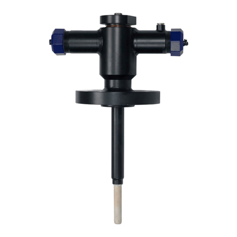
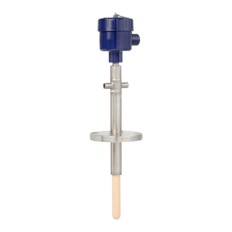
Examples, models IBF1, IBF3 Examples, models IBM2, IBM3
Example, model IBJ4 Example, model IBS3
DE
EN
Operating instructions
Betriebsanleitung
Models IBF1, IBF2, IBF3, IBM2, IBM3, IBJ4, IBS3
Typen IBF1, IBF2, IBF3, IBM2, IBM3, IBJ4, IBS3

2
14613009.01 08/2023 EN/DE
DE
EN
WIKA operating instructions, models IBF1, IBF2, IBF3, IBM2, IBM3, IBJ4, IBS3
Models IBF1, IBF2, IBF3, IBM2, IBM3, IBJ4, IBS3
Typen IBF1, IBF2, IBF3, IBM2, IBM3, IBJ4, IBS3
Seite 31 - 57
© 08/2023 WIKA Alexander Wiegand SE & Co. KG
All rights reserved. / Alle Rechte vorbehalten.
WIKA®is a registered trademark in various countries.
WIKA®ist eine geschützte Marke in verschiedenen Ländern.
Prior to starting any work, read the operating instructions!
Keep for later use!
Vor Beginn aller Arbeiten Betriebsanleitung lesen!
Zum späteren Gebrauch aufbewahren!

EN
WIKA operating instructions, models IBF1, IBF2, IBF3, IBM2, IBM3, IBJ4, IBS3
14613009.01 08/2023 EN/DE
3
Contents
Contents
1.
2.
3.
4.
5.
7.

EN
14613009.01 08/2023 EN/DE
4WIKA operating instructions, models IBF1, IBF2, IBF3, IBM2, IBM3, IBJ4, IBS3
1.
The monoblock described in the operating instructions has been
designed and manufactured using state-of-the-art technology. All
components are subject to stringent quality and environmental
accordance with ISO 9001.
These operating instructions contain important information on
handling the product.Working safely requires that all safety
instructions and work instructions are observed.
Observe the relevant local accident prevention regulations and
general safety instructions for the product's application area.
The operating instructions are part of the product and must be kept in
the immediate vicinity of the product and readily accessible to skilled
personnel at any time. Pass the operating instructions on to the next
operator or owner of the product.
Skilled personnel must have carefully read and understood the
operating instructions prior to beginning any work.
operating instructions, the English wording shall prevail.
The general terms and conditions contained in the sales
documentation shall apply.
Further information:
- Internet address: www.wika.de / www.wika.com
Model Data sheet
IBF1 AC 09.30
IBF2, IBF3 AC 09.25
IBM2, IBM3 AC 09.24
IBJ4, IBS3 AC 09.26

EN
WIKA operating instructions, models IBF1, IBF2, IBF3, IBM2, IBM3, IBJ4, IBS3
14613009.01 08/2023 EN/DE
5
1.1
... indicates a directly dangerous situation resulting in serious
injury or death, if not avoided.
... indicates a potentially dangerous situation that can result in
serious injury or death, if not avoided.
... indicates a potentially dangerous situation that can result in
light injuries or damage to property or the environment, if not
avoided.
... indicates a potentially dangerous situation that can result in
burns, caused by hot surfaces or liquids, if not avoided.
... points out useful tips, recommendations and information for

EN
14613009.01 08/2023 EN/DE
6WIKA operating instructions, models IBF1, IBF2, IBF3, IBM2, IBM3, IBJ4, IBS3
2.
2.1
valves to separate the process from the instrument side and a vent valve.
The modular design allows using an arrangement of ball valves and/or
needle valves.
Handle T-handle
Lever handle Coloured dust cap
Valve stem with sealing packing Gland nut
Ball Valve spindle
Seat with soft sealing ring Seal bush
Metal sealing ring Sealing packing
Valve body Locking pin
Locking plate Bonnet body
Locking pin Spindle tip
Valve body
Ball valve Needle valve
Antistatic design
Ball
Conductive
connection between
ball and valve stem
Valve stem

EN
WIKA operating instructions, models IBF1, IBF2, IBF3, IBM2, IBM3, IBJ4, IBS3
14613009.01 08/2023 EN/DE
7
Models IBJ4, IBS3
With this monoblock design the media is typically sampled from or inject-
ed to the centre of the pipeline.
Model IBJ4 is always equipped with an additional check valve to prevent
O-ring
Valve poppet
Spring
Clamping rings
Valve body
2.2
Model Vent
IBF1 Single block 1 -
IBF2, IBM2 Single block-and-bleed 1 1
IBF3, IBM3,
IBS3, IBJ4 1)
Double block-and-bleed 2 1
1)
2.3
Cross-check scope of delivery with delivery note.
All other required parts, such as seals, threaded studs, nuts and plug
screws, must be procured by the customer for an optimal adaptation to
the process.
Check valve

EN
14613009.01 08/2023 EN/DE
8WIKA operating instructions, models IBF1, IBF2, IBF3, IBM2, IBM3, IBJ4, IBS3
3.
3.1
The monoblock models have been designed to meet the requirements
of the process industry, especially for use in applications with aggressive
gaseous and highly viscous liquid media even in aggressive environ-
separate the process. Except model IBF1 all monoblock models are
equipped with a vent valve for draining or venting. The valves must only
be used in fully open or fully closed position.
Models IBF1, IBS2, BF3, IBM2, IBM3
These valves are used for the separation of measuring instruments from
the process.
Model IBJ4
The monoblock for injection processes has been designed to enter a
medium through an injection quill into a pressurised system.
Model IBS3
The monoblock for sampling processes has been designed to extract a
medium from a pressurised system.The sampling probe allows to extract
media for analysis.
Only use the product in applications that lie within its technical perfor-
mance limits (e.g. max. ambient temperature, material compatibility, ...).
Improper handling or operation of the product outside of its technical
specifications requires the instrument to be taken out of service
immediately and inspected by an authorised service engineer.

EN
WIKA operating instructions, models IBF1, IBF2, IBF3, IBM2, IBM3, IBJ4, IBS3
14613009.01 08/2023 EN/DE
9
These valves do not have their own potential ignition source. The
responsibility for the safe use in hazardous areas in accordance with
the accepted standards of technology rests with the operator.
For the reasons mentioned above, these valves are not marked and do
not have their own certification.
The product has been designed and built solely for the intended use
described here, and may only be used accordingly.
The manufacturer shall not be liable for claims of any type based on
operation contrary to the intended use.
3.2
performance limits or is not compatible with the materials.
permissible.
Improper use of the product can lead to hazardous situations
and injuries.
Refrain from unauthorised modifications to the product.
Do not use the product with abrasive media.
improper use.
3.3
The product is used in the industrial sector. The operator is therefore
responsible for legal obligations regarding safety at work.
The safety instructions within these operating instructions, as well as the
safety, accident prevention and environmental protection regulations for
the application area must be maintained.

EN
14613009.01 08/2023 EN/DE
10 WIKA operating instructions, models IBF1, IBF2, IBF3, IBM2, IBM3, IBJ4, IBS3
The operator is obliged to maintain the product label in a legible
condition.
To ensure safe working on the product, the operating company must
ensure the following:
The operating personnel are regularly instructed in all topics
and know the operating instructions and in particular, the safety
instructions contained therein.
The operating personnel have read the operating instructions and
taken note of the safety instructions contained therein.
The intended use for the application is complied with.
required tightening torques of the screw connections are observed
during mounting.The dependence of a multitude of factors for the
parts used (threaded bolts, nuts, seals, lubricants) and the respective
Following testing, improper use of the product is excluded.
3.4
Improper handling can result in considerable injury and
damage to property.
The activities described in these operating instructions
may only be carried out by skilled personnel who have the
Skilled personnel, authorised by the operator, are understood to be
personnel who, based on their technical training, knowledge of measure-
ment and control technology and on their experience and knowledge
capable of carrying out the work described and independently recognis-
ing potential hazards.


EN
WIKA operating instructions, models IBF1, IBF2, IBF3, IBM2, IBM3, IBJ4, IBS3
14613009.01 08/2023 EN/DE
11
The personnel trained by the operator are understood to be personnel
who, based on their education, knowledge and experience, are capable
of carrying out the work described and independently recognising poten-
tial hazards.
Special operating conditions require further appropriate knowledge, e.g.
of aggressive media.
3.5
The personal protective equipment is designed to protect the skilled
personnel from hazards that could impair their safety or health during
work.When carrying out the various tasks on and with the product, the
skilled personnel must wear personal protective equipment.
The requisite personal protective equipment must be provided by the
operating company.
Wear safety goggles!
Wear protective gloves!
Protect hands from friction, abrasion, cuts or deep injuries
and also from contact with hot surfaces and aggressive
media.

EN
14613009.01 08/2023 EN/DE
12 WIKA operating instructions, models IBF1, IBF2, IBF3, IBM2, IBM3, IBJ4, IBS3
Part number
Process connection
Instrument connection
TAG number
Vent connection
Product traceability information (production date, lot number etc.)
4.
4.1
Check the product for any damage that may have been caused by trans-
port. Obvious damage must be reported immediately.
When unloading packed goods upon delivery as well as
during internal transport, proceed carefully.
With internal transport, observe the instructions in chapter

EN
WIKA operating instructions, models IBF1, IBF2, IBF3, IBM2, IBM3, IBJ4, IBS3
14613009.01 08/2023 EN/DE
13
4.2
Do not remove the packaging until just before commissioning.
Keep the packaging as it will provide optimum protection during transport
(e.g. change in installation site, sending for repair).
Storage temperature: -50 ... +70 °C [-58 ... +158 °F]
Humidity: 35 ... 85 % relative humidity (no condensation)
Direct sunlight or proximity to hot objects
Mechanical vibration, mechanical shock (putting it down hard)
Soot, vapour, dust and corrosive gases
conditions listed above. If the original packaging is not available and if
the product is stored for a prolonged period of time (more than 30 days),
place a bag containing a desiccant inside the packaging.
During storage valves shall be kept in close position to avoid ingresss
corrosion during storage: it is not a substitute for paint or other means of
protective coating to be applied to the valve once installed.
additional protection once installed.Valves shall be handled by use of
lifting lugs or other suitable lifting devices. It is suggested not to lift the
valves by means of valve handles.

EN
14613009.01 08/2023 EN/DE
14 WIKA operating instructions, models IBF1, IBF2, IBF3, IBM2, IBM3, IBJ4, IBS3
5.
Torque wrench set, open-ended spanner set (13 ... 32 mm)
Allen key set
Screwdriver
Suitable lubricants for sealing elements and threaded bolts
Suitable sealing material for threaded connections
Before installation, commissioning and operation, ensure that the appro-
priate product has been selected in terms of operating conditions, design
Only use original parts.
Always observe the mounting and operating instructions of accessories
when commissioning them.
or toxic substances), harmful media (e.g. corrosive, toxic,
carcinogenic, radioactive), and also with refrigeration plants
and compressors, there is a danger of physical injuries and
damage to property and the environment.
Aggressive media with extremely high temperature and under
high pressure may be present at the product.
For these media, in addition to all standard regulations,
the appropriate existing codes or regulations must also be
followed.
Wear the requisite protective equipment (see chapter 3.5

EN
WIKA operating instructions, models IBF1, IBF2, IBF3, IBM2, IBM3, IBJ4, IBS3
14613009.01 08/2023 EN/DE
15
With the pressurisation of the product, as a result of poor
sealing, media under high pressure can escape. Due to the
high energy of the media that can escape in the event of
a failure, the possibility of physical injuries and damage to
property exists.
The sealing of the connections must be carried out expertly
and checked for leak tightness.
Defective valves must be isolated and repaired or replaced.
The operator must be aware of the consequences prior to
Suitable lifting equipment must be used for the safe
handling of heavy products.
5.1
Just before installation unpack the valve and remove protection caps.
attached to the valve body.
Check for damage and internal and external corrosion. If a return is
Ensure that all unused connections are closed. Plug screws for vent
The valve may only be carried by the valve body, not by the handle.

EN
14613009.01 08/2023 EN/DE
16 WIKA operating instructions, models IBF1, IBF2, IBF3, IBM2, IBM3, IBJ4, IBS3
Before mounting, ensure that the process line has been
depressurised using the main valve.
It is suggested to clean pipeline connection before the installation of
bodies or dirt from the internal of the pipeline.
Inspect the functionality of the valve by opening and closing several
Ball valves shall be in open position during the installation to avoid
their damage.
Ensure that all process and instrument connections are free from
damage, rust, dust or foreign bodies.
The correct sealing element must be used for the respective
connection.
After mounting the monoblock on the process connection, the instru-
ment must be installed.
Beware of welding operations at the pipeline. Ensure that the
temperature does not exceed 150 °C [302 °F]. Always keep
the ball valve in open position.
To screw in threaded connections the appropriate tool must only be
Models IBJ4 and IBS3
The sampling probe/injection quill is solidly attached to the valve and it is
-
tion-free operation, wake frequency calculations are recommended.
WIKA provides support collars and is able to perform wake frequency
calculations on request.
5.2
To close the ball valve, turn the handle 90° in a clockwise direction as far
as the stop.To open the ball valve, turn the handle 90° anticlockwise as
far as the stop.

EN
WIKA operating instructions, models IBF1, IBF2, IBF3, IBM2, IBM3, IBJ4, IBS3
14613009.01 08/2023 EN/DE
17
During operation the vent line must be closed and usually a plug screw is
installed to close the vent connection.
Please note that the handle may present a slight play and spin
freely up to a quarter turn when in the depressurised state.
This is due to the constructive design.
The valve, especially the handle, must not be subjected to any exter-
nal loading (e.g. use as a climbing aid, support for objects).
The handle may only be used by hand; the use of tools is not
accepted.
The torque on reaching the valve stop must only be hand-tight.
Ensure that all valves of the product are closed.
Before venting the product, the process line must be closed securely.
Make sure that the vent connection points away from personnel and
high pressure ejection of parts is avoided by a protective device. Then
remove plug screw, if present.To open the needle valve, turn the T-han-
dle anticlockwise as far as the stop. To close the needle valve, turn the
T-handle clockwise as far as the stop.

EN
14613009.01 08/2023 EN/DE
18 WIKA operating instructions, models IBF1, IBF2, IBF3, IBM2, IBM3, IBJ4, IBS3
1. Ensure that all valves of the product are closed.
2. Open the main valve of the process line.
3. Make sure that the vent valve (red) remains closed.
It is recommended to purge the entire pipeline with inert gas
(e. g. nitrogen) before pressurising it with process media.
While purging, the valve shall be cycled a few times to ensure
full purging of the valve body cavity. It is the responsibility of
Model IBF1 Models IBF2, IBM2 Models IBF3, IBM3
Model IBS3 Model IBJ4

EN
WIKA operating instructions, models IBF1, IBF2, IBF3, IBM2, IBM3, IBJ4, IBS3
14613009.01 08/2023 EN/DE
19
4.
The pressure is at the instrument connection now. The valve shall be
cycled a few times to ensure equal pressurisation of the valve body
cavity.
5. After the pressurisation, set the valve in the required position.
5.3 Leak test
The monoblock has been already pneumatically and hydrostatically
tested, so it does not need to be retested on site.
It is the responsibility of the operator to make a leak test at the process
and connections (e.g. leak spray and bubble method).
The following table contains the most frequent causes of
faults and the necessary countermeasures.
Lubrication problem due to
unchanged valve position for a
long time period
Perform a functional test
as described in chapter
7.1 Maintenanceand
shorten inspection interval
as appropriate
Defective parts due to
corrosion, process conditions,
age
Replace product
Overtightened gland nut,
defective sealing packing
Replace product
needle valve
bonnet
Leaking sealing packing See „Fixing a leak at the

EN
14613009.01 08/2023 EN/DE
20 WIKA operating instructions, models IBF1, IBF2, IBF3, IBM2, IBM3, IBJ4, IBS3
Valve closed or partially open Ensure that that valve is
open
Incorrect mounting Ensure that that valve is
correctly mounted
Clogging by unsuitable
process media
Check compatibility of
process media
If faults cannot be eliminated by means of the listed
measures, the product must be taken out of operation
immediately.
Ensure that there is no longer any pressure present and
protect against being put into operation accidentally.
Contact the supplier.
If a return is needed, please follow the instructions given in
Upon contact with hazardous media (e.g. oxygen, acetylene,
-
sive, toxic, carcinogenic, radioactive), and also with refriger-
ation plants and compressors, there is a danger of physical
injuries and damage to property and the environment.
Should a failure occur, aggressive media with extremely high
temperature and under high pressure or vacuum may be
present at the product.
For these media, in addition to all standard regulations,
the appropriate existing codes or regulations must also be
followed.
Wear the requisite protective equipment (see chapter
Other manuals for IBF1
1
This manual suits for next models
6
Table of contents
Languages:
Other WIKA Measuring Instrument manuals