manuals.online logo
Brands
  1. Home
  2. •
  3. Brands
  4. •
  5. Fema
  6. •
  7. Measuring Instrument
  8. •
  9. Fema VIR-30 Series User manual

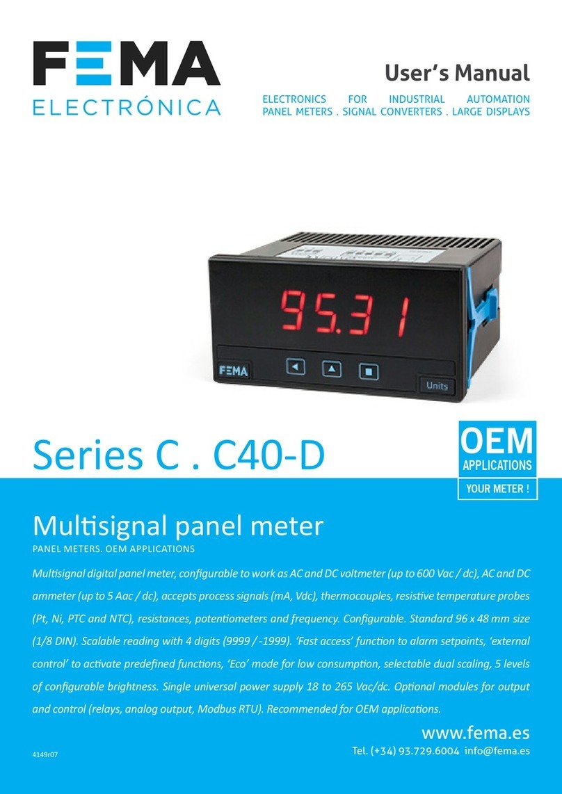
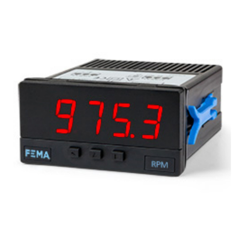
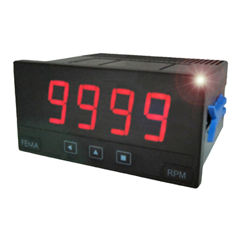
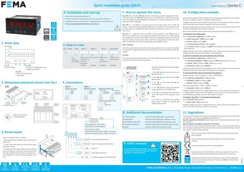
Fema VIR-30 Series User manual

Series VIR-30
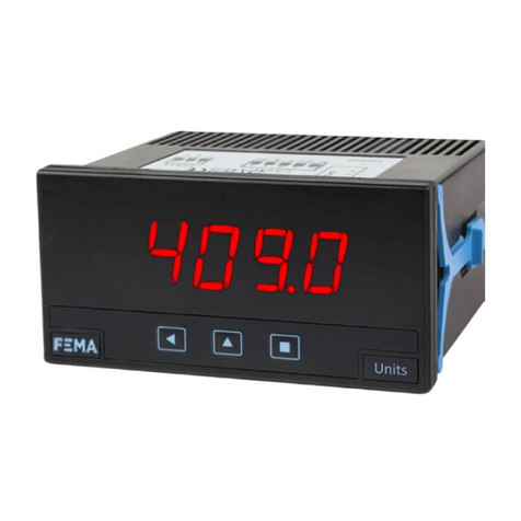
Panel meter 72x36 mm Low-Cost
Low-cost panel meter for active process signals in mA and Vdc. Small size
72x36 mm and standard 14mm digit height. Reading scalable to engineering
units. Instrument readjustable by potentiometers accesible at the rear of the front
lter. Multiple power options in AC and DC.
Model VIR-30-32 for process signals
Low-Cost
Panel Meters
FEMA ELECTRÓNICA
USER’S MANUAL
(1169R01)
User’s Manual VIR-30-32
FEMA ELECTRÓNICA - Page 3
Panel Meter VIR-30-32
Panel meter 72x36mm for process signals
Low-cost panel meters for active process signals in mA and
Vdc, with display reading in engineering units..
Instruments with 3 digits, allow to display from -999 up to
999 with decimal point selection. Display reading is scalable
to engineering units through span and offset potentiometers
accessible at the rear of the front lter. Input range selection
through internal solder jumpers.
Excellent digit readability, with high quality leds and anti-
rreexive front lter. Easy panel xation. Connections with
plug-in screw terminals on the rear of the instrument.
VIR-30 32 0
Model Power
-0 (230 Vac)
-1 (115 Vac)
-2 (24 Vac)
-3 (48 Vac)
-6 (10 to 30 Vdc)
---4/20mA
Signal
4/20 mA
0/10 Vdc
=---
Otras
-65 (IP65)
-(vacio)
Reading
0/999 mm
0/2.50 Bar
-20/350 Kg
...
-
Order Reference
0/999mm
Digits 3
Type 7 segments, red
Height 14 mm
Maximum display 999
Minimum display -999
Decimal point selectable 8.8.8
Overrange “XXX” ashing
Underrange “-XXX” ashing
Display refresh 4 per second
Signals accepted mA, Vdc
Ranges in mA 4/20mA, 0/20mA
Ranges in Vdc 0/10Vdc, 0/100Vdc, 0/450Vdc
Connections 2 wire
Signal type active
Power
Options in AC 230Vac, 115Vac, 48Vac, 24Vac
Options in DC 10-30 Vdc isolated
Consumption <3.5W
Isolation 2KV (powered in AC)
500V (powered in DC)
Conguration by internal potentiometers at the
rear of the front lter, and solder-
jumpers to select input ranges
Mechanical
Mounting panel
Connections plug-in screw terminals
Weight <150 grams
Housing material ABS black color
Front size 72x36mm
Panel cut-out 69x32.5mm
Deep 75mm (including terminal)
Protection IP30
Temperature
Operation temperature 0 to 50ºC
Storage temperature –20 to +70ºC
Technical Data
User’s Manual VIR-30-32
FEMA ELECTRÓNICA - Page 2
User’s Manual VIR-30-32
FEMA ELECTRÓNICA - Page 3
Front View and Connections
DP1 = XX.X
Signal
45
3
2
1
+
-
A B C D
Offset light P1
(±20 points)
P2 Span light
(±50 points)
P3 Span
DP2 = X.XX
Internal Conguration
Offset P4
Signal Close Jumpers
4/20 mA J1 - J4 - J5 - J6
0/20 mA J1 - J4 - J5 - J6
0/10 Vdc J3 - J6
0/100 Vdc J2 - J6
0/450 Vdc J4 - J11
Note .- J12a always closed. J7,
J10, J12b always open.
J1
Upper Module
seen on solder side
J11
J6
J9 J8 J7
J3
J4
J10
J2
J5
J12a
J12b
Offset Type Jumpers
Offset Negative J8 Closed
(by default) J9 Open
Offset Positive J8 Open
J9 Closed
Power
-
+
Manufacturer FEMA ELECTRÓNICA, S.A.
Pol. Ind. Santiga - Altimira 14
E-08210 - Barberà del Vallès - BARCELONA
ESPAÑA - SPAIN
www.fema.es - [email protected]
Series VIR-30
Models 01,03,04,05,06,08,10,15,20,21,32,51 and 90
The manufacturer declares that the instruments indicated
comply with the directives and rules indicated below.
Directive of electromagnetic compatibility 2004/108/CEE
Directive of low voltage 73/23/CEE
Safety Requirements 61010-1
Equipment “Fixed”, “Permanently connected”
Pollution degree 1, Isolation Double, CAT-II
Emmision requirements
UNE EN 50081-1 (1994)
Immunity requirements
UNE EN 50082-1 (1998)
Barberà del Vallès, April 2010
Daniel Juncà - Quality Manager
CE Declaration of Conformity
INSTALLATION - The power supply circuit must be provided
with a device that permits disconnection if needed. The power
supply type and value, and its connection, are printed on the
labels attached to the instrument. The instrument does not
have internal protection fuse. To meet safety requirements,
the installation of a fuse is needed with the values indicated
below :
230Vac 115Vac
Fuse 50 mA 100 mA
MAINTENANCE - Before any operation of maitenance,
adjustment, repair or substitution, the instrument must be
unplugged from the power supply. To clean the instrument
use a humid cloth. Do not use abrasive products (solvents,
alcohols, ...) to clean the front lter and plastic parts. Do not
operate the instrument in places with excess of humidity,
smoke, or ammable gas. The instrument is designed to be
mounted on metalic panel.
IN CASE OF FIRE 1- Disconnect the instrument from the
power supply. 2- Give alarm according to local rules. 3- Switch
off air conditioning devices. 4- Attack the re with carbonic
snow. Do not use water. In closed areas do not use systems
with vaporized liquids.
Prescriptions
Mechanical Dimensions (mm)
69
32,5 Panel cut-out
15
60
5
5 max
72
36
Large Displays
60 & 100 mm digit
Signal Converters
& Isolators
Panel Meters
Standard 96x48
other products
Panel Meters
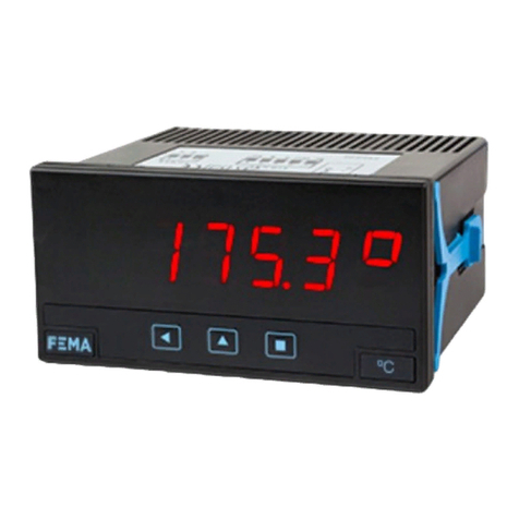
Standard 96x48mm
Panel Meters
Miniature 48x24 mm
Panel Meters
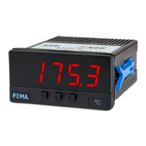
Small 72x36 mm

This manual suits for next models

1

Other Fema Measuring Instrument manuals

Fema TAS-1-IDC User manual

Fema

Fema TAS-1-IDC User manual

Fema LP4 User manual

Fema

Fema LP4 User manual

Fema M Series User manual

Fema

Fema M Series User manual

Fema I3 Series User manual

Fema

Fema I3 Series User manual

Fema S40-C1 User manual

Fema

Fema S40-C1 User manual

Fema K Series User manual

Fema

Fema K Series User manual

Fema M60-C1 User manual

Fema

Fema M60-C1 User manual

Fema S Series User manual

Fema

Fema S Series User manual

Fema M40 Series User manual

Fema

Fema M40 Series User manual

Fema C Series User manual

Fema

Fema C Series User manual

Fema M Series User manual

Fema

Fema M Series User manual

Fema C Series User manual

Fema

Fema C Series User manual

Fema M40-D User manual

Fema

Fema M40-D User manual

Popular Measuring Instrument manuals by other brands

Bosch GIS 1000 C Professional Original instructions

Bosch

Bosch GIS 1000 C Professional Original instructions

Bosch GLL 150 E Operating/safety instructions

Bosch

Bosch GLL 150 E Operating/safety instructions

wirsbo FlowMaster user manual

wirsbo

wirsbo FlowMaster user manual

ELGO Electronic LMIX2 Series operating manual

ELGO Electronic

ELGO Electronic LMIX2 Series operating manual

PCB Piezotronics 301A12 Installation and operating manual

PCB Piezotronics

PCB Piezotronics 301A12 Installation and operating manual

BRUEL & KJAER 1616 instruction manual

BRUEL & KJAER

BRUEL & KJAER 1616 instruction manual

microguard 414 Operator's manual

microguard

microguard 414 Operator's manual

HACH LANGE EVITA OXY Series Basic user manual

HACH LANGE

HACH LANGE EVITA OXY Series Basic user manual

ABB MagMaster MF/F Upgrade

ABB

ABB MagMaster MF/F Upgrade

Kaelus iXA quick start guide

Kaelus

Kaelus iXA quick start guide

Halma Alicat Scientific L quick start guide

Halma

Halma Alicat Scientific L quick start guide

AMTAST UV340B Operation manual

AMTAST

AMTAST UV340B Operation manual

Trotec 8016 Speedy 100 fiber Operation manual

Trotec

Trotec 8016 Speedy 100 fiber Operation manual

SensorLink 8-117 XT 50HZ Operator's manual

SensorLink

SensorLink 8-117 XT 50HZ Operator's manual

Hach 500sc SiO2 Operations

Hach

Hach 500sc SiO2 Operations

Onicon F-3200 Series Installation & operation guide

Onicon

Onicon F-3200 Series Installation & operation guide

PRECISION DIGITAL vantageview Safe Touch PD6700 instruction manual

PRECISION DIGITAL

PRECISION DIGITAL vantageview Safe Touch PD6700 instruction manual

Gemo B52 operating instructions

Gemo

Gemo B52 operating instructions

manuals.online logo
manuals.online logoBrands
  • About & Mission
  • Contact us
  • Privacy Policy
  • Terms and Conditions

Copyright 2025 Manuals.Online. All Rights Reserved.