Please read and understand setup guide prior to installing the Electric Actuator!
!
"#$!%"&'()*+,!$--(./+0(-'1!$-234!!!!!5!!!!!67758995:7;6!!!!!5!!!!!<<<3/&0/++/2=>,-+'32(>!
Attaching the Electric Actuator to the Rascal –
The electric actuator will replace the square hand jack on the front of the Rascal. The square hand
jack will need to be removed in order for the electric actuator to be installed. Make sure to keep the
bottom bolt that attaches the square hand jack to the Rascal, as this will be needed to secure the
electric actuator back in its place.
1. To attach the electric actuator to the Rascal the square hand jack will need to be removed. Before
removing the square hand jack, ensure that the Rascal is securely hooked to a tow vehicle.
2. Once the Rascal is fully secure to the tow vehicle, lower the finish rake on the back of the Rascal down
to a 90 degree angle.
3. Now raise the wheels of the Rascal till the finish rake and scarifier’s/profile blade(s)/Vibraflex rest on
the ground. The square hand jack should be loose, and able to slide back and forth on the securing pin and
bolt at the bottom. If it is not able to be moved, turn the handle either raising or lowering the wheels till
the square hand jack is able to move freely.
4. Remove the lynch pin at the end of the securing pin, and slide the pin back so the square hand jack is
able to be moved out of the way. If the securing pin lynch pin is on the top link side, the pin will need to
be fully removed and reinserted so that the lynch pin is on the electric actuator side. Note** if the pin will
not easily move, turn the top link using the center handle till the pin can be removed, or slide back out of
the way.
5. With the square hand jack moved out of the way, remove the bolt from the bottom of the square hand
jack using a ¾” combination wrench and a ¾” Socket with wrench. Set the bolt off to the side as it will be
needed to install the electric actuator.
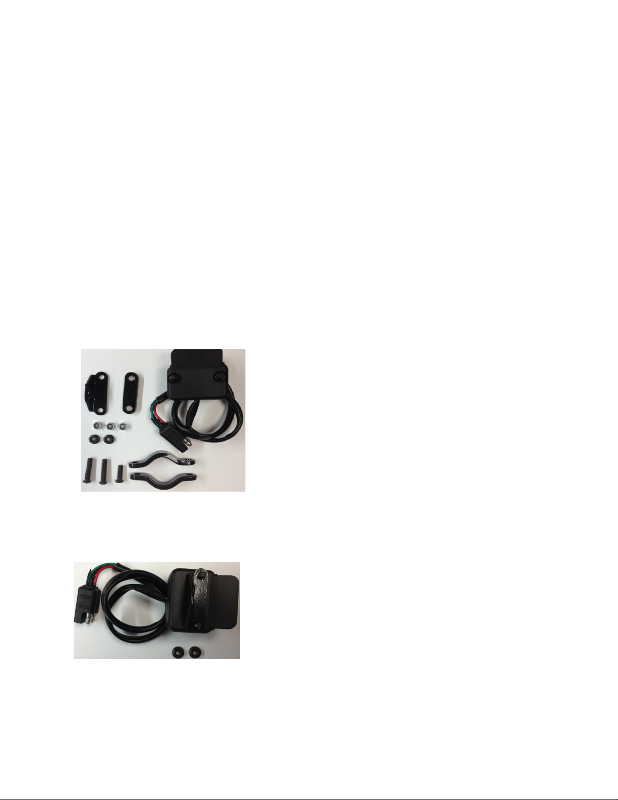
6. Using the ½” bolt that was removed from the square hand jack, attach the bottom of the actuator to the
Rascal frame.
7. Connect the end of the two prong cable coming from the actuator to the two prong cable coming from
the control box.
8. Now hold onto the black motor portion of the electric actuator, and use the switch from the ATV side
wiring harness to raise the actuator up to the securing pin. Note** if the electric actuator does not make a
sound, or does not move; make sure that all of the wiring harness is properly connected together, and try
again. If the electric actuator still does not move or make a sound please contact the ABI Customer
Service team for additional trouble shooting solutions.
9. With the actuator fully raised, slide the pin into the eye located half way up the shaft of the electric
actuator.