Abilia Emfit Epilepsy Alarm User manual

Rev F1 EN
Emfit®Tonic-Clonic Seizure Monitor
Art.no 464000, 464031
Note! The device must not be used if an operational failure of the device might lead to a
delay in getting the appropriate treatment or medication for the patient, which could put the
patients life at risk.
Manual

2

3
Table of Contents
1. Important safety precautions.........................................................................................5
1.1 Important information and limitations for use. Read before use..............................5
1.2 Unintended adjustment of control unit settings:......................................................5
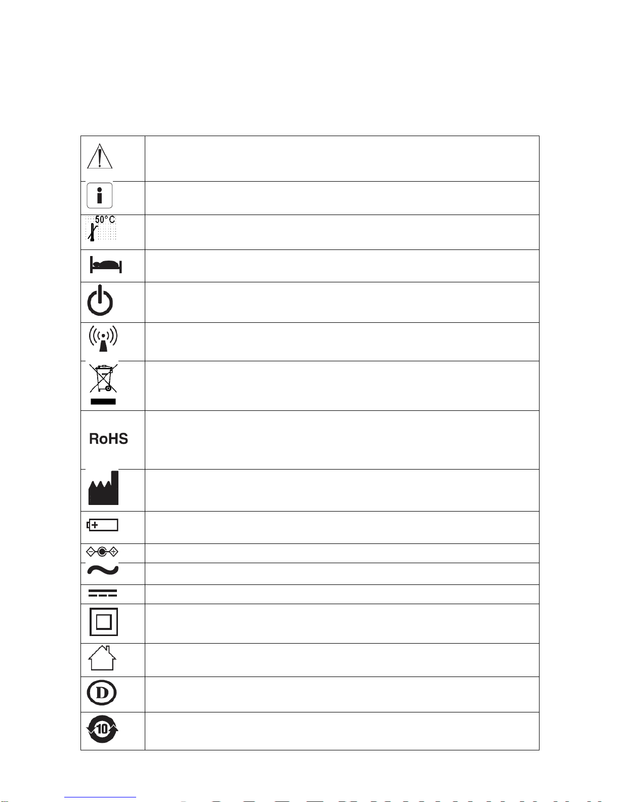
2. Symbols used in these instructions for use ...................................................................6
3. Introduction ...................................................................................................................8
3.1 Product description.................................................................................................8
3.2 Intended use...........................................................................................................8
3.3 Intended user and operator ....................................................................................9
3.4 Liability of the manufacturer....................................................................................9
3.5 About these instructions for use..............................................................................9
4. Package contents........................................................................................................10
5. General .......................................................................................................................10
5.1 Control unit (picture 1)..........................................................................................10
5.2 Bed sensor (picture 6) ..........................................................................................10
6. Setting up the DIP switches ........................................................................................11
6.1 Adjusting the tonic-clonic seizure notification delay (switches 1 & 2)....................11
6.2 Setting the Bed-Exit Notification Delay.................................................................12
6.3 SW 1 switch function (switch 6)............................................................................12
6.4 Adjusting the notification sound volume (switches 7 and 8)..................................12
7. Inserting batteries and battery service life...................................................................13
8. 5V AC External power supply (optional)......................................................................14
9. Connectors and cables................................................................................................15
9.1 X2 (AUX) Connector Pin Order (picture 16)..........................................................15
10. Installation of the control unit.......................................................................................15
10.1 With wall mounting bracket...................................................................................15
10.2 With bed side clip..................................................................................................15
10.3 On table................................................................................................................15
11. Installation of the bed sensor ......................................................................................16
12. SW1 press switch (picture 21).....................................................................................17
12.1 ON/OFF switch.....................................................................................................17
12.2 Acknowledgement switch .....................................................................................17
12.3 Bed exit alarm bypass switch ...............................................................................17
12.4 Bed exit alarm “presence / absence” sensitivity switch.........................................17
13. Signal lights (picture 22)..............................................................................................18
13.1 Green –Presence.................................................................................................18
13.2 Blue –Device on/standby.....................................................................................18
13.3 Red –Malfunction.................................................................................................18
14. Signal sounds..............................................................................................................19
14.1 Alarm signals........................................................................................................19
14.2 Information signals................................................................................................19
15. Setting sensitivity to notice tonic-clonic seizure...........................................................20

4
16. Calibrating the “presence / absence” sensitivity ..........................................................20
16.1 Doing calibration...................................................................................................20
16.2 Error messages and how to handle them .............................................................21
17. Checks........................................................................................................................21
17.1 Weekly checks......................................................................................................21
17.2 Start-up and monthly checks ................................................................................21
18. Troubleshooting...........................................................................................................22
19. Cleaning......................................................................................................................23
20. Disposal of the device after use ..................................................................................23
21. Declaration of conformity (EU) ....................................................................................23
22. Abilia limited warranty statement.................................................................................23
22.1 Your guarantee.....................................................................................................23
22.2 Terms ...................................................................................................................23
22.3 Exclusions and limitations.....................................................................................24
22.4 Your legal rights reserved.....................................................................................25
23. Technical specifications ..............................................................................................26
23.1 Control unit ...........................................................................................................26
23.2 Sensor..................................................................................................................26
23.3 External Power Supply .........................................................................................27
23.4 Ambient conditions ...............................................................................................27
23.5 Product class........................................................................................................27
24. Electromagnetic conditions .........................................................................................28
25. Manufacturer...............................................................................................................31
26. Appendix - Related pictures........................................................................................32

5
1. Important safety precautions
1.1 Important information and limitations for use. Read before use.
- Must not be used in situations where a delay in the arrival of appropriate medical care, could
lead to a potentially life-threatening situation.
- This device is designed only to be used as an aid for a caregiver.
- Pets can cause false notifications or prevent a notification when needed if they walk or lie on a
bed fitted with this device.
- Do not use this device for any purpose other than that specified by the manufacturer.
- Do not connect the device to any other devices other than those specified by the manufacturer.
- Do not try to repair the device yourself.
- No maintenance of the product is allowed during use.
- Do not move or transport the device during use. If the bed equipped with the device needs to
be moved remember to unplug all cables and turn off power. Fix the control unit to the bed with
bed-side attachment clip to prevent it from moving.
- This product is for indoor use only.
- The device is designed to be used in the electromagnetic environment and conditions specified
on chapter Electromagnetic conditions.
- The client or user of the device must ensure that it is only used in the specified ambient
conditions.
- Do not install this device near or on top of another device. However, if this cannot be avoided,
the user must ensure that the device functions in the normal manner.
- Do not use X1, X2 or X3 connectors for any purpose other than that specified by the
manufacturer. Do not connect the connectors to e.g. telecommunications or local area
networks.
- If this device is used with a pressure care mattress filled using a compression pump, the device
may not function normally in some cases.
- Equipment is not suitable for use in the presence of a flammable anaesthetic mixture with air or
with oxygen or nitrous oxide.
- Do not let the device get wet.
- Remove the batteries when the device is not in use or when it is stored for an extended period.
Alkaline batteries may become selfdischarged, start leaking and contaminate the device.
- Do not use any rechargeable batteries or lithium-ion batteries! Rechargeable or lithium-ion
batteries carry the risk of melting, ruining the device and causing possible danger to the user.
- The device is not diagnostic and cannot differentiate between a tonic-clonic seizure and other
fast movements.
- When removing the power supply from the socket, ensure that the plug part is not left in the
socket. If the plug part is left in the socket, touching or trying to remove it carries the risk of an
electric shock.
- Keep device cords out of the reach of children (risk of strangulation). Use protective cord
covers or cable ties to securely attach and hide cords to prevent strangulation. Keep cords as
short as possible and secure them so that they are out of reach of children.
1.2 Unintended adjustment of control unit settings:
- Adjusting the volume may lead to the notification sound not being heard.
- Increasing sensitivity may lead to false notifications while decreasing sensitivity may lead to the
notification not becoming activated when needed.
- Incorrect positioning of the DIP switches may interfere with the normal operation of the device.
- Pressing the ON/OFF/Reset (SW1) press switch for too long will switch off the device.

6
2. Symbols used in these instructions for use
The following instructions are designed to ensure the personal safety of the user and
protect this device or any device connected to it from damage. These instructions use
symbols to draw the user's attention to the instructions at hand. The symbols act as safety
and warning signs. The symbols and their explanations are as follows:
If the instructions are not adhered to, the situation may lead to a death or
serious personal injury (in these instructions for use). ATTENTION - consult
accompanying documents (i.e. these instructions for use)
Means that the section contains important information for the user (in these
instructions for use).
Indicates the maximum use and storage temperature of the bed sensor.
When led next to this is blinking it indicates person is in bed (in the control
unit)
When led next to this is blinking it indicates product is in stand-by mode (in
the control unit).
Non-ionizing radiation (in these instructions for use, chapter
Electromagnetic conditions).
Symbol of European Waste Electrical and Electronic Equipment Directive
(WEEE Directive) 2002/96/ EC on waste electrical and electronic
equipment (in these instructions for use and on bed sensor).
Indicates that the product is in compliance with the European directive
2002/95/EC on the restriction of the use of certain hazardous substances in
electrical and electronic equipment (commonly referred to as the Restriction
of Hazardous Substances Directive or RoHS).
Indicates manufacturer’s name and address (in the control unit and bed
sensor).
Indicates positioning of battery cell. + is positive terminal and - is negative
terminal (in the control unit).
Indicates polarity of d.c. power connector (In the external power supply).
Indicates alternating current (in the external power supply).
Indicates direct current (in the external power supply).
Indicates that product meets safety requirements specified in IEC 61140 for
Class II equipment (In the external power supply).
Product is for indoor use only (in the external power supply).
Product is UL Demko certified (in the external power supply).
Product is China SJ/T 11363-2006 certified (in the external power supply).

7
Product is UL certified (in the external power supply).
Indicates that the product conforms with the relevant requirements of the
Medical Device Directive 93/42/EEC.
Product is VCCI certified (in the external power supply).
Product is UKRSepro certified (in the external power supply).
Product is GOST-R certified (in the external power supply).
Product is C-TICK certified (in the external power supply).
Product is China RoHS 30 certified (in the external power supply).
Product is BSMI certified (in the external power supply).
Product is SIQ certified (in the external power supply).
Product is IRAM certified (in the external power supply).
Product is CCC certified (in the external power supply).
Product is CPSQ certified (in the external power supply).
Product is PSE to J60950 certified (in the external power supply).

8
3. Introduction
These instructions for use describe the use of the Emfit MM, Tonic-Clonic Seizure
Monitor. The version number and details can be found in chapter 23. Technical
specifications.
Use the device only in the ambient conditions specified by the manufacturer. For
detailed information, refer to Technical Specifications in these instructions for use.
Follow all instructions provided in this document concerning the installation, use and
cleaning of the device.
Based on the intended use, point 1) of section 3.2 below, the Emfit Tonic-Clonic
Seizure Monitor is a medical device as defined in the Medical Device Directive
93/42/EEC. Based on the nature of point 2) regarding the intended use, the device is
not defined as a medical device (Directive 93/42/EEC, Article 1(2), subparagraph a).
The device is a Class I medical device in accordance with the Medical Device
Directive 93/42/EEC and carries the CE marking accordingly.
3.1 Product description
Emfit Tonic-Clonic Seizure Monitor (later “product”) is a movement monitor that is used to
detect and notify tonic-clonic seizures.
The product consists of a bed sensor located under the mattress and a control unit where
the bed sensor is connected. Control unit should be placed on a table, clipped on bed or
mounted on wall.
The control unit notifies caregiver by flashing led and sound (unless muted) and/or
transfers a notification via external system e.g. a nurse call system or a personal
emergency phone.
Operating environment is typically bedroom at care-home or home.
3.2 Intended use
The product is intended to be used to assist in sensory monitoring and to notify the
caregiver
1) of the body movements of a person lying on a mattress equipped with the under-
mattress sensor due to a tonic-clonic seizure while sleeping.
2) of the presence of the monitored person on the mattress equipped with the under-
mattress bed sensor and if he or she gets up from the mattress.
The device may either be used
solely for the task described in point 1) above,
for the tasks described in points 1) and 2) above simultaneously.
NOTE 1
The manufacturer cannot guarantee that the device will detect all episodes of tonic-clonic
seizure-induced body movements of the monitored person.
NOTE 2
The device may trigger a false body movement notification, especially if the person lying
on the mattress fitted with the under-mattress bed sensor is awake.

9
NOTE 3
The device cannot be used to verify whether the alerted body movement was caused by a
tonic-clonic seizure. The occurrence of a tonic-clonic epileptic seizure can be verified,
among other things, against electroencephalogram (EEG) data interpreted by a healthcare
professional. The product cannot replace an EEG recording system.
NOTE 4
Always ensure the suitability of the device - particularly for small children - by conducting a
test run. There are no weight or age restrictions for the use of the device.
3.3 Intended user and operator
The intended user of the product is the monitored person.
The intended operator is the caregiver of the user. The operator needs to be adult who
fully understands instructions and limitations of use mentioned in these instructions for
use. Otherwise no special skills or knowledge is needed for the operator.
3.4 Liability of the manufacturer
Abilia is liable to ensure the safety, reliability and performance of the device, provided that:
the device is installed, used and cleaned in accordance with the instructions in these
instructions for use
any changes to the product, maintenance and repairs are conducted by a person
trained by Abilia or its representative
any spare parts or accessories used have been approved by Abilia.
3.5 About these instructions for use
Read all warnings and reminders in these instructions for use with care to avoid any
hazardous situations and damage.

10
4. Package contents
•A control unit (D-1090-2G) (picture 1)
•A bed sensor (L-4060SL or L-4060SLC) (picture 6)
•Two pieces 3M double-sided tape to fix the sensor (picture 26)
•A wall mounting bracket with two screws and two plugs (picture 7)
•Clip for bed side attachment (picture 8)
•These instructions for use
•Two AA size 1.5 V alkaline batteries
•External power supply (This part is not included unless it has been ordered as a
spare part) (see chapter Technical Specifications for details) (picture 2)
5. General
5.1 Control unit (picture 1)
The control unit emits a notification via dry-contact output and by sound (unless muted)
when the sensor detects fast-paced movement (frequency 3–20Hz) in the bed for the
duration of the preset time (10, 13, 16 or 20 sec.).
The control unit operates with 2 pcs AA size 1.5 V alkaline batteries. An external power
supply is available. Do not use any power supply other than that provided by Abilia. (see
chapter Technical Specifications for details) (picture 2). In the event of a power failure, two
high-quality 1.5V AA alkaline batteries can be used as an emergency power supply. Do
not use any rechargeable batteries or lithiumion batteries! Rechargeable or lithium-ion
batteries carry the risk of melting, ruining the device and causing possible danger to the
user.
The control unit has an input connector for the bed sensor (X3) and power supply (X1).
The device also has a connector (X2) to transfer the notification via an external system
e.g. a nurse call system or a personal emergency phone.
Next to the input connector, there is a push button (SW1) that can be used to acknowledge
a notification or as an on/off switch. (picture 3)
The control unit has 8 DIP switches (picture 4) to select the settings and a rotary switch to
adjust the sensitivity of the device. (picture 5)
5.2 Bed sensor (picture 6)
The bed sensor produces a millivolt alternating current when detecting movement. The
control unit calculates the frequency and scale of the movement from this signal and, on
this basis, detects possible tonic-clonic seizure. Micro-movement from heartbeat allow the
device to detect the person's presence.

11
6. Setting up the DIP switches
Open the lid of the control unit by lifting it from the side (picture 9). Inside, you will find
eight DIP switches that are used to select the desired functions (picture 4). Remember to
select the desired settings using the DIP switches before using the device.
The control unit has the following factory settings. DIP 1, 2, 4, 5, 6, 7 and 8 OFF (down).
DIP 3 ON (up). With these settings:
Movement notification delay is 13 seconds.
The SW1 switch acts as the On/Off switch which means that the device can be
switched on or off by pressing the switch for three (3) seconds.
The notification sound is loudest.
The bed exit notification is disabled.
Remove the batteries and disconnect the device from the power supply and
remove nurse call cable (if used) from connector X2 before opening the lid.
Remove the batteries and disconnect the power supply before setting up the DIP
switches in order to implement the new settings.
6.1 Adjusting the tonic-clonic seizure notification delay (switches 1 & 2)
When the device detects faster movement (between 3–20Hz), its internal timer switches
on. The device gives a notification if the movement continues for longer than the preset
time. The desired delay should be set up according to the table below.
The factory setting is 13 seconds. If the user makes other habitual movements, such as
rocking, scratching or restlessness, a longer delay time can be selected to avoid false
notifications.
Setting the fast movements duration after
which the notification goes off
Switch 1
Switch 2
10 seconds
ON (up)
ON (up)
13 seconds (default)
OFF (down)
OFF (down)
16 seconds
ON (up)
OFF (down)
20 seconds
OFF (down)
ON (up)

12
6.2 Setting the Bed-Exit Notification Delay
The device can be set to trigger notification when person leaves the bed and system does
not notice any micro-movements.
Time delay
Switch 3
Switch 4
Switch 5
No Delay
OFF (down)
OFF (down)
OFF (down)
Disabled (default)
ON (up)
OFF (down)
OFF (down)
3min Delay
ON (up)
ON (up)
OFF (down)
6min Delay
OFF (down)
OFF (down)
ON (up)
10min Delay
ON (up)
OFF (down)
ON (up)
15min Delay
OFF (down)
ON (up)
ON (up)
30min Delay
ON (up)
ON (up)
ON (up)
6.3 SW 1 switch function (switch 6)
SW 1 switch function
Switch 6
The SW1 switch acts as the On/Off switch which means that the
device can be switched on or off by pressing the switch for three
(3) seconds.
OFF
(down)
The SW1 switch does not act as the On/Off switch. The device is
always on when it is connected to the power supply or when the
batteries are in.
ON (up)
6.4 Adjusting the notification sound volume (switches 7 and 8)
There are four volume levels: Very loud, normal, quiet and mute. The factory setting is
very loud. Volume level should be set so that notification is audible in the environment of
use.
Level
Switch 7
Switch 8
Very loud
OFF (down)
OFF (down)
Normal
ON (up)
OFF (down)
Quiet
OFF (down)
ON (up)
Mute
ON (up)
ON (up)
The notification sound stops when the SW1 switch is pressed or when the seizure stops.
Remove the batteries and disconnect the power supply before setting up the DIP
switches in order to implement the new settings.

13
7. Inserting batteries and battery service life
Disconnect the device from the power supply and remove nurse call cable (if
used) from connector X2 before opening the lid.
Product operates with 2 pcs high quality AA size 1.5 V alkaline batteries (operating voltage
2x1.5V = 3V). Install and remove the batteries as follows:
1) Open the lid by removing the screws and lifting it from one side (for first-time assembly:
the screws for the lid can be found in the pouch containing wall mounting parts). (picture 9)
2) Insert two high-quality AA size 1.5V alkaline batteries into the device following the
polarity symbols at the bottom of the device. Close the lid and screw the screws back on.
(picture 10)
The easiest way to remove a battery is by lifting it from the + end. (picture 11)
Estimated battery life is 3 months when using high quality alkaline batteries with 2800 mAh
capacity (2pcs). Estimation is based on measured battery consumption in various
conditions and then a calculation where device is on 50% of time (shut down 50% of time)
and of that 50% of time there is someone in bed 75% of that time, there are two
notifications per day and sound notification is on 30 seconds each time.
When the batteries are getting low, the red LED will begin to flash slowly. A
“beep” sound will be heard after every 1.5 hours and the dry-contact output will
give a low battery notification after every 3 hours.
NOTE! All alkaline batteries start to leak when empty, and a leak will
contaminate the device. Remember to replace the batteries at least once a year
to avoid any leaks. Remove the batteries when the device is not being used or
when it is being stored for an extended period. Disconnect the power supply
briefly to test the batteries. If the batteries are empty, the red light on the control
unit will flash every fourth time compared to blue light. The X2 connector and the
connected system will also trigger a notification. Replace the batteries when
necessary.
Product is tested and safe to use with following two alkaline batteries:
Manufacturer: Duracell Type: AA 1.5V Model: MN1500 LR6
Manufacturer: Energizer Type: AA 1.5V Model: E91 LR6 AM3
Do not use any rechargeable batteries or lithium-ion batteries! Rechargeable or
lithium-ion batteries carry the risk of melting, ruining the device and causing
possible danger to the user.

14
8. 5V AC External power supply (optional)
Set up the power supply in the following manner:
Remove the plastic cover (if
applicable). (picture 23)
Select a suitable plug from
the four alternatives.
(picture 24)
Plug in the plug and ensure
that it is not loose. (picture
25)
The control unit has been designed and tested to be used with the Globtek inc.
power supply (see chapter Technical Specifications for details). Using any other
power supply may interfere with the safe use of the device.
When the power supply is connected, the batteries act as backup power supply
in the event of a power failure. All alkaline batteries self-discharge and start to
leak when empty, contaminating the device. Ensure that batteries are replaced
at least once a year.
When removing the power supply from the socket, ensure that the plug part is
not left in the socket. If the plug part is left in the socket, touching or trying to
remove it carries the risk of an electric shock.
Keep device cords out of the reach of children (risk of strangulation). Use
protective cord covers or cable ties to securely attach and hide cords to prevent
strangulation. Keep cords as short as possible and secure them so that they are
out of reach of children.

15
9. Connectors and cables
Connector symbols can be found at the bottom of the
control unit. (picture 3)
vX1 Connector for an external power supply. Only
use Globtek inc. power supply (see chapter Technical Specifications for details) which can
be obtained as an original accessory from Abilia.
X2 AUX Connector to connect the device to a nurse call system, a personal
emergency phone or an external wireless transmitter. The connector may only be
connected to a system safety voltage input with max. voltage below 25 V(AC) / 60 V (DC),
where both poles have been separated from the electrical network. Max. load current
100 mA.
X3 - Sensor connector. Only use the Emfit bed sensor.
Connect the bed sensor (picture 13), the power supply delivered as an accessory (picture
14) and any connector cables (picture 15) according to the pictures.
9.1 X2 (AUX) Connector Pin Order (picture 16)
From left to right:
Pin 1
Common return
Pin 2
Normally Open (NO) send
Pin 3
Normally Closed (NC) send
Pin 4
Low Battery send (NC)
Pin 5
Not in use, do not connect
Pin 6
Not in use, do not connect
Pin 7
Not in use, do not connect
Pin 8
Not in use, do not connect
10. Installation of the control unit
10.1With wall mounting bracket
1) Fix the mounting bracket onto a wall with the plugs and screws supplied. (picture 17)
2) Slide the control unit onto the wall mounting bracket. (picture 18)
3) Press the control unit down until you hear a click. (picture 19)
10.2With bed side clip
Press the control unit down to the clip. (picture 20)
10.3On table
Place the control unit on the table led lights facing upwards.

16
11. Installation of the bed sensor
Place the bed sensor across the bed, under the mattress at
approximately chest height. (picture 12)
To prevent the bed sensor from moving, fix the sensor to the
bed bottom or mattress using the double sided tape provided
or e.g. cable ties (picture 26). The tape will not leave a mark
and it will come off as a whole if removed.
Check at least once a week that the bed sensor is properly
positioned.
If using the bed sensor with a spring mattress, place the sensor
beneath the mattress and on top of the box spring or
flat/platform surface. Place above spring mattress and below a
mattress pad if bed is especially springy, you do not have a flat
surface to place sensor on, individual being monitored weighs
less than 35 lbs/15 kgs, or if alarm does not trigger with sensor
below mattress after increasing sensitivity to maximum level allowed (Manufacturer
recommendation is no higher than 8). Thickness of mattress and weight of individual may
require that sensor be placed above the mattress and below a mattress pad.
Always place the bed sensor under the mattress or mattress topper, never just under the
sheet. The bed sensor must not come into direct contact with a person!
The bed sensor is designed to last for a minimum of two (2) years placed under a foam
mattress and against the hard base of a bed frame.
With a spring mattress, the service life of the bed sensor may be considerably shorter.
When the bed sensor is placed on a spring mattress, the user's weight and movement may
cause the sensor to crumple, which may affect the sensor's performance. The
manufacturer recommends that users replace the sensor when it starts to look crumpled.
When used with a spring mattress, the sensor should be replaced annually. The warranty
does not cover damage caused by crumpling.
If the bed sensor is used with a pressure care mattress that is adjusted using a
compressor pump, the mattress may interfere with the sensor's performance. If you are
unsure about the suitability of your mattress, please contact the manufacturer.
Keep device cords out of the reach of children (risk of strangulation). Use protective
cord covers or cable ties to securely attach and hide cords to prevent strangulation. Keep
cords as short as possible and secure them so that they are out of reach of children.

17
12. SW1 press switch (picture 21)
12.1ON/OFF switch
The SW1 switch acts as the on/off switch if this function is
activated (DIP switch 6 is down).
Press the SW1 switch for three (3) seconds in order to
activate or deactivate the control unit. When the control unit is
switched on, you will hear a beep and the blue LED light will start to flash. When the
device is switched off, you will hear a "beep-beep-boop" (high-high-low) sound. The blue
LED light will go off.
12.2Acknowledgement switch
The notification sound (if activated) can be muted by pressing the SW1 switch shortly. The
device will make a "beep-beep" sound.
NOTE! If you press the switch for too long, you might accidentally switch off the device.
The notification sound will also stop when the fast-paced movements stop.
12.3Bed exit alarm bypass switch
The SW1 switch acts as the bypass switch for bed exit alarm if this function is activated
and person wants to exit the bed without causing an alarm. Note! This feature will not work
if any bed exit delay is being used!
Before leaving the bed press SW1 shortly to hear sound “beep beep”. You now have 20
seconds to leave the bed without causing a bed exit alarm. If you do not leave the bed
within 20 seconds the device will re-activate.
12.4Bed exit alarm “presence / absence” sensitivity switch
SW1 switch can be used to launch automatic calibration for presence / absence sensitivity.
See chapter 16. Calibrating the “presence / absence” sensitivity.

18
13. Signal lights (picture 22)
13.1Green –Presence
Light flashes every second time
compared to blue light.
A person is on the bed or other movement is
being made.
Light flashes the same speed as blue
light.
A person has been on the bed for 60 seconds
and the device has become activated.
Light flashes rapidly.
Fast-paced movement on the bed detected.
Light is off.
No one is on the bed.
13.2Blue –Device on/standby
Light is off.
Device is switched off.
Light flashes slowly.
Device is switched on.
Light flashes rapidly a few times.
Device triggers a notification.
13.3Red –Malfunction
Light is flashing the same speed as blue
light
Bed sensor is disconnected or defective.
Signal alarm sounds after 10 seconds and
then every 45 seconds. There is also an alarm
sent through the X2 connector after 30
seconds and then every 30 minutes.
Light is flashing every fourth time
compared to blue light.
Batteries are empty. Replace batteries.

19
14. Signal sounds
There are two types of signal sounds.
Alarm signals, that are long and loud, are used to notify about fast movements and bed
exit. Alarm signals can be muted using the DIP switches (see chapter 6.4 Adjusting the
notification sound volume).
Information signals, that are short and quieter than alarm signals, are used as feedback to
the user. Information signals tell the user when the device is turned on or off or when
alarm signal is acknowledged. Possible malfunctions of the equipment (disconnected bed
sensor, empty batteries) and feedback about calibration of the sensor are also notified with
information signals. Information signals can’t be muted.
Alarm signals are high priority signals that will overrule information signals if both signals
activate simultaneously.
14.1Alarm signals
Two high and low “BEEPS” in a loop.
Fast movements alarm goes off.
Three high and low “BEEPS” in a loop.
Bed exit alarm goes off.
14.2Information signals
Short, high “BEEP”.
SW1 is pressed and device turns on.
Short, low “BEEP”.
SW1 is pressed and device is turned off.
Short, low “BEEP” x 2.
SW1 has been pressed once and alarm signal
is acknowledged.
Short, high “BEEP” x 3 and short low
“BEEP” x 3.
Sensor is disconnected or broken. Information
signal sounds after 10 seconds of
disconnection and then every 45 seconds.
Short, high “BEEP”, short “LOW” beep.
Batteries are empty. Replace batteries.
Short, high “BU-BEEP” x 3.
Sensitivity calibration has started / successful
calibration.
Short, low “BEEP” (after calibration).
Sensitivity too low.
Short, low “BEEP” (after calibration) x 2.
Sensitivity too high.

20
15. Setting sensitivity to notice tonic-clonic seizure
The sensitivity to notice fast movements caused by tonic-clonic
seizure can be adjusted with the 10-position rotary switch inside
(see picture 5). The factory default setting is 3.
Use following table to make a pre-adjustment per person weight
BUT adjust it if needed either up or down. If you feel that
sensitivity is not good enough, simply adjust higher step by step.
Or, if you feel it is too sensitive causing false notifications, simply
drop the setting lower step by step.
Test it so that when person is in bed, gentle tapping of mattress nearby sensor should start
the green led blinking faster which indicates fast movements are detected. If not, adjust
higher. However, when person is lying still it should not start blinking fast without reason. If
so, adjust lower.
During rest the green led should blink the same speed as blue led. If person is rolling over
in bed, lights may momentarily blink faster. This type of normal movement in bed should
not last long enough for the notification to sound.
Person weight
Switch position
(in parenthesis if false alarms occur)
>75 kg
1 (0)
50-75 kg
2 (1)
35-50 kg
3 (2 or 1)
25-35 kg
4 or 5 (3 or 2)
15-25 kg
6 or 7 (5 or 4)
<15 kg
8 or 9 (7 or 6)
Adjust the sensitivity of the device every time the sensor is re-installed, if the
user or the sensor changes.
16. Calibrating the “presence / absence” sensitivity
16.1Doing calibration
If you use the bed-exit (absence) notification, the sensitivity to determine that person is in
or out of the bed is adjusted in calibration mode. The person to be monitored should be in
bed and lying still (not moving or talking) for at least one (1) minute until green light starts
to blink the same speed as blue light. The monitor (control unit) should be placed on a
table, clipped on bed, or mounted on wall. Do not hold monitor in hand while testing.
Sensor should be in correct position under mattress.
Start calibration by pressing the SW1 switch (picture 21) three (3) times. You will hear 3
low and high tones (bu-beep, bu-beep, bu-beep). The calibration takes 18 seconds. If
calibration is successful, the confirmation sound will be the same 3 low and high tones (bu-
beep, bu-beep, bubeep).
This manual suits for next models
8
Table of contents