Abit KV8-MAX3 User manual

KV8/KV8-MAX3
AMD AthlonTM 64 System Board
Socket 754
User’s Manual
4200-0410-01
Rev. 1.00

Copyright and Warranty Notice
The information in this document is subject to change without notice and does not
represent a commitment on part of the vendor, who assumes no liability or
responsibility for any errors that may appear in this manual.
No warranty or representation, either expressed or implied, is made with respect to the
quality, accuracy or fitness for any particular part of this document. In no event shall
the manufacturer be liable for direct, indirect, special, incidental or consequential
damages arising from any defect or error in this manual or product.
Product names appearing in this manual are for identification purpose only and
trademarks and product names or brand names appearing in this document are the
property of their respective owners.
This document contains materials protected under International Copyright Laws. All
rights reserved. No part of this manual may be reproduced, transmitted or transcribed
without the expressed written permission of the manufacturer and authors of this
manual.
If you do not properly set the motherboard settings, causing the motherboard to
malfunction or fail, we cannot guarantee any responsibility.
KV8/KV8-MAX3

Table Of Contents
Chapter 1. Introduction .......................................................................... 1-1
1-1. Features & Specifications ........................................................................1-1
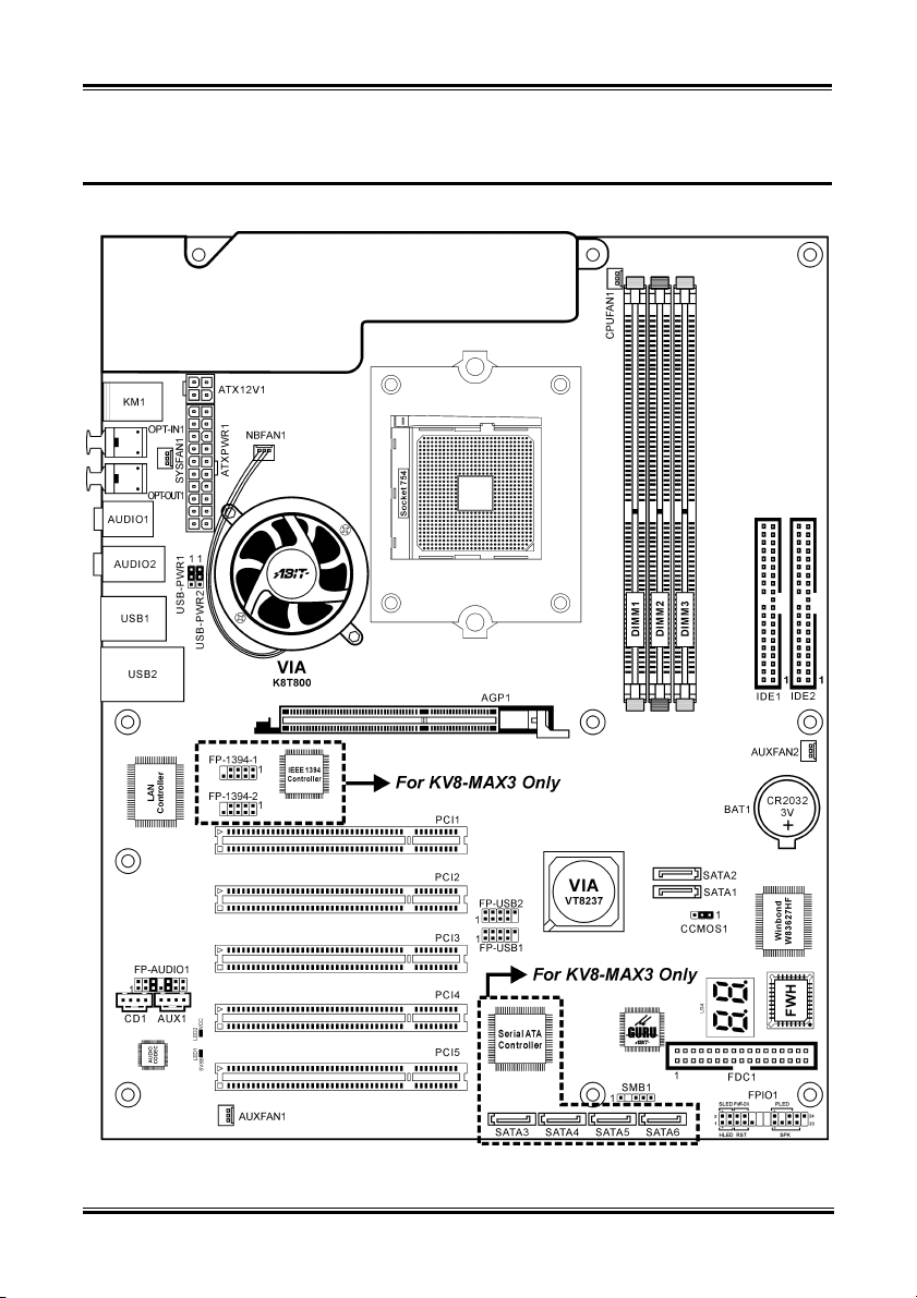
1-2. Layout Diagram .......................................................................................1-3
Chapter 2. Hardware Setup.................................................................... 2-1
2-1. Install The Motherboard...........................................................................2-1
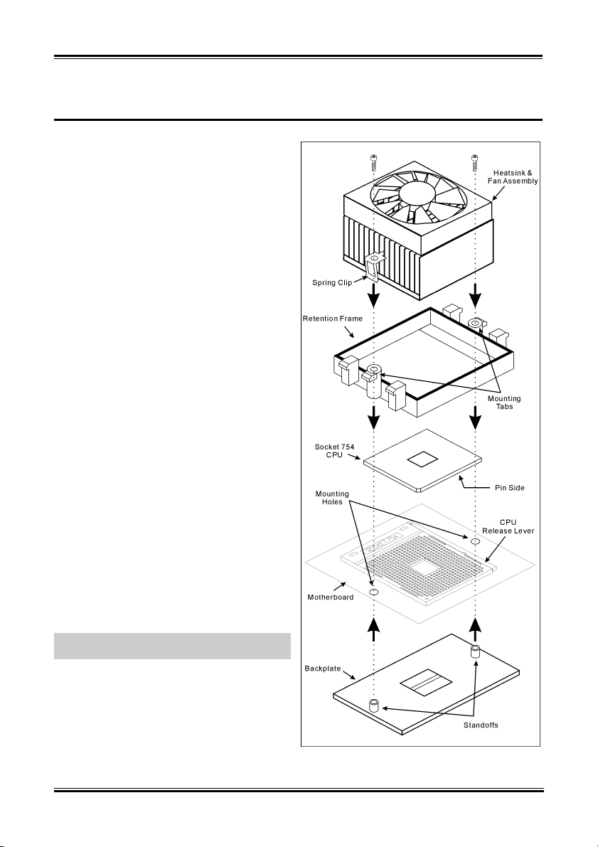
2-2. Install CPU and Heatsink.........................................................................2-2
2-3. Install System Memory ............................................................................2-3
2-4. Connectors, Headers and Switches ..........................................................2-5
(1). ATX Power Input Connectors........................................................2-5
(2). FAN Connectors.............................................................................2-6
(3). CMOS Memory Clearing Header ..................................................2-7
(4). Wake-up Header.............................................................................2-8
(5). Front Panel Switches & Indicators Headers ..................................2-9
(6). Additional USB Port Headers......................................................2-10
(7). Additional IEEE1394 Port Header (KV8-MAX3) ......................2-11
(8). Front Panel Audio Connection Header ........................................2-12
(9). Status Indicators...........................................................................2-13
(10). Accelerated Graphics Port Slot....................................................2-13
(11). Floppy Disk Drive Connector......................................................2-14
(12). Internal Audio Connectors ...........................................................2-14
(13). IDE Connectors............................................................................2-15
(14). POST Code Display .....................................................................2-16
(15). Serial ATA Connectors .................................................................2-17
(16). System Management Bus Headers...............................................2-17
(17). Back Panel Connectors ................................................................2-18
Chapter 3. BIOS Setup............................................................................ 3-1
3-1. SoftMenu Setup........................................................................................3-3
3-2. Standard CMOS Features.........................................................................3-5
3-3. Advanced BIOS Features.........................................................................3-8
3-4. Advanced Chipset Features....................................................................3-10
3-5. Integrated Peripherals ............................................................................3-14
3-6. Power Management Setup .....................................................................3-17
3-7. PnP/PCI Configurations.........................................................................3-19
User’s Manual

3-8. PC Health Status ....................................................................................3-21
3-9. Load Fail-Safe Defaults .........................................................................3-24
3-10. Load Optimized Defaults .......................................................................3-24
3-11. Set Password ..........................................................................................3-24
3-12. Save & Exit Setup ..................................................................................3-24
3-13. Exit Without Saving...............................................................................3-24
Appendix A. Install VIA 4-in-1 Driver ................................................................. A-1
Appendix B. Install Audio Driver ......................................................................... B-1
Appendix C. Install LAN Driver ........................................................................... C-1
Appendix D. Install VIA USB 2.0 Driver .............................................................D-1
Appendix E. Install VIA Serial ATA RAID Driver.............................................. E-1
Appendix F. Install Silicon Serial ATA RAID Driver (KV8-MAX3).................. F-1
Appendix G. Install ABIT µGuru Driver..............................................................G-1
Appendix H. POST Code Definition .....................................................................H-1
Appendix I. Troubleshooting (Need Assistance?)................................................ I-1
Appendix J. How to Get Technical Support .........................................................J-1
KV8/KV8-MAX3

Introduction 1-1
Chapter 1. Introduction
1-1. Features & Specifications
1. CPU
• Supports 64-bit AMD AthlonTM 64 processor (Socket 754)
• 1600MHz system bus using HyperTransportTM technology
2. CPU Integrated Memory Controller
• 72-bit memory controller supports DDR at 266, 333 and 400MHz
• Support 3 DIMM up to 2GB Max.
• Support 3 DIMM DDR 333
• Support 2 DIMM DDR 400
3. Chipset
• VIA K8T800 + VT8237
• Supports 1600MHz HyperTransport
• Supports Advanced Configuration and Power Management Interface (ACPI)
• Accelerated Graphics Port connector supports AGP 8X/4X (0.8V/1.5V)
4. SATA RAID
• Supports SATA data transfer rates at 150 MB/s (1.5G bps)
• Supports SATA RAID 0/1 JBOD
5. 2nd SATA RAID (KV8-MAX3)
• On board Serial ATA RAID PCI Controller
• Supports 4 x SATA 150 RAID 0/1/0+1
6. Gigabit LAN
• On board 10/100/1000M PCI Ethernet Controller
7. IEEE 1394a (KV8-MAX3)
• Supports IEEE 1394a at 400/200/100 Mb/s transfer rate
8. Audio
• Onboard 6-Channel AC 97 CODEC
• Professional digital audio interface supports optical S/PDIF Input/Output
9. ABIT Engineered
• ABIT µGuruTM Technology
• ABIT OTESTM Technology
• ABIT SoftMenuTM Technology
• CPU ThermalGuardTM Technology
User’s Manual

1-2 Chapter 1
10. Internal I/O Connectors
• 1x AGP 8X/4X slot
• 5x PCI slots
• 1x floppy port supports up to 2.88MB
• 2x Ultra DMA 33/66/100/133 connectors
• 2x Serial ATA 150 RAID connectors
• 4x Serial ATA 150 RAID connectors (KV8-MAX3)
• 2x USB headers
• 2x IEEE 1394a headers (KV8-MAX3)
• 1x CD-IN, 1x AUX-IN header
11. Back Panel I/O
• 1x PS/2 keyboard, 1x PS/2 mouse
• 1x S/PDIF In connector
• 1x S/PDIF Out connector
• 5 holes Audio connector (Front Speaker, Line-In, Mic-In, Center/Sub, Surround Speaker)
• 4x USB, 1x RJ-45 LAN Connector
• 1x IEEE 1394a Connector (KV8-MAX3)
12. Miscellaneous
• ATX form factor: 305 x 245 mm
13. Order Information
Model Features
KV8 OTES, uGuru, GbE
KV8-MAX3 OTES, uGuru, GbE, Secure IDE, IEEE1394, Sil3114 SATA
Specifications and information contained herein are subject to change without notice.
KV8/KV8-MAX3

Introduction 1-3
1-2. Layout Diagram
User’s Manual

1-4 Chapter 1
KV8/KV8-MAX3

Hardware Setup 2-1
Chapter 2. Hardware Setup
Before the Installation: Turn off the power supply switch (fully turn off the +5V standby power), or
disconnect the power cord before installing or unplugging any connectors or add-on cards. Failing to do
so may cause the motherboard components or add-on cards to malfunction or damaged.
2-1. Install The Motherboard
Most computer chassis have a base with many mounting holes to allow motherboard to be securely
attached on and at the same time, prevented from short circuits. There are two ways to attach the
motherboard to the chassis base:
1. use with studs
2. or use with spacers
In principle, the best way to attach the board is to
use with studs. Only if you are unable to do this
should you attach the board with spacers. Line up
the holes on the board with the mounting holes on
the chassis. If the holes line up and there are
screw holes, you can attach the board with studs.
If the holes line up and there are only slots, you
can only attach with spacers. Take the tip of the
spacers and insert them into the slots. After doing
this to all the slots, you can slide the board into
position aligned with slots. After the board has been positioned, check to make sure everything is OK
before putting the chassis back on.
ATTENTION: To prevent shorting the PCB circuit, please REMOVE the metal studs or spacers if they
are already fastened on the chassis base and are without mounting-holes on the motherboard to align with.
User’s Manual

2-2 Chapter 2
2-2. Install CPU and Heatsink
This motherboard provides a ZIF (Zero Insertion
Force) Socket 754 to install AMD Socket 754
CPU. The CPU you bought should contain with a
kit of heatsink, cooling fan, retention frame and
blackplate. If that’s not the case, buy one specially
designed for Socket 754.
Please refer to the figure shown here to install
CPU and heatsink. (For reference only. Your
Heatsink & Fan Assembly may not be exactly the
same as this one.)
1. Locate the Socket 754 on this motherboard.
Pull the CPU release lever sideways to
unlatch and then raise it all the way up.
2. Drop the processor with its pin side down into
the CPU socket. Do not use extra force to
insert CPU; it only fits in one direction. Close
the CPU release lever.
3. Align the Backplate Standoffs with the
mounting holes on motherboard. Position the
backplate onto motherboard.
4. Place the Retention Frame onto the
motherboard and align it with the Backplate
Standoffs.
5. Place heatsink on top of CPU, and make sure
the heatsink fits properly on the retention
frame.
6. Hook both sides of the Spring Clip onto the
Mounting Tabs of Retention Frame. Tighten
screws until the Spring Clip is fully installed.
7. Attach the fan connector of Heatsink & Fan
Assembly with the CPU-FAN connector on
the motherboard.
ATTENTION: Do not forget to set the correct
bus frequency and multiple for your processor.
KV8/KV8-MAX3

Hardware Setup 2-3
2-3. Install System Memory
This motherboard provides 3 184-pin DDR DIMM slots for memory expansion available from minimum
128MB to maximum 2GB.
Table 2-1. Valid Memory Configurations
Bank Memory Module Total Memory
Bank 0, 1 (DIMM1) 128, 256, 512MB, 1GB 128MB ~ 1GB
Bank 2, 3 (DIMM2) 128, 256, 512MB, 1GB 128MB ~ 1GB
Bank 4, 5 (DIMM3) 128, 256, 512MB, 1GB 128MB ~ 1GB
Total System Memory 128MB ~ 2GB
Table 2-2. AMD Athlon 64 Processor Memory Supporting sets
DRAM
number DIMM1 DIMM2 DIMM3 Memory spec
2 x8 single rank or x16 x8 single rank or x16 empty DDR400
2 x8 single rank or x16 x8 double rank empty DDR400
2 x8 single rank or x16 empty x8 single rank or x16 DDR400
2 x8 single rank or x16 empty x8 double rank DDR400
2 x8 double rank x8 single rank or x16 empty DDR400
2 x8 double rank x8 double rank empty DDR400
2 x8 double rank empty x8 single rank or x16 DDR400
2 empty x8 single rank or x16 x8 single rank or x16 DDR333
3 x8 double rank x8 single rank or x16 x8 single rank or x16 DDR333
3 x8 single rank or x16 x8 single rank or x16 x8 single rank or x16 DDR333
User’s Manual

2-4 Chapter 2
Power off the computer and unplug the AC power cord before installing or removing memory modules.
1. Locate the DIMM slot on the board.
2. Hold two edges of the DIMM module
carefully, keep away of touching its
connectors.
3. Align the notch key on the module with the
rib on the slot.
4. Firmly press the module into the slots until
the ejector tabs at both sides of the slot
automatically snaps into the mounting notch.
Do not force the DIMM module in with extra
force as the DIMM module only fit in one direction.
5. To remove the DIMM modules, push the two ejector tabs on the slot outward simultaneously, and
then pull out the DIMM module.
ATTENTION: Static electricity can damage the electronic components of the computer or optional
boards. Before starting these procedures, ensure that you are discharged of static electricity by touching a
grounded metal object briefly.
KV8/KV8-MAX3

Hardware Setup 2-5
2-4. Connectors, Headers and Switches
Here we will show you all of the connectors, headers and switches, and how to connect them. Please read
the entire section for necessary information before attempting to finish all the hardware installation inside
the computer chassis. A complete enlarged layout diagram is shown in Chapter 1 for all the position of
connectors and headers on the board that you may refer to.
WARNING: Always power off the computer and unplug the AC power cord before adding or removing
any peripheral or component. Failing to so may cause severe damage to your motherboard and/or
peripherals. Plug in the AC power cord only after you have carefully checked everything.
ATX Power Input Connectors
(1).
This motherboard provides two power connectors to connect to an ATX12V power supply.
NOTE: It is recommended to connect to a power supply with 350W, 20A +5VDC capacity at least for
heavily loaded system, and 2A +5VSB capacity at least for supporting wake-up features.
User’s Manual

2-6 Chapter 2
(2). FAN Connectors
These 3-pin connectors each provide power to the cooling fans installed in your system.
The CPU must be kept cool by using a powerful fan with heatsink. The system is capable of monitoring
the speed of the CPU fan.
• CPUFAN1: CPU Fan
• NBFAN1: Chipset Fan
• SYSFAN1: OTES Fan
• AUXFAN1, AUXFAN2: Auxiliary Fan
WARNING: These fan connectors are not jumpers. DO NOT place jumper caps on these connectors.
KV8/KV8-MAX3

Hardware Setup 2-7
(3). CMOS Memory Clearing Header
This header uses a jumper cap to clear the CMOS memory.
• Pin 1-2 shorted (default): Normal operation.
• Pin 2-3 shorted: Clear CMOS memory.
WARNING: Turn the power off first (including the +5V standby power) before clearing the CMOS
memory. Failing to do so may cause your system to work abnormally or malfunction.
User’s Manual

2-8 Chapter 2
(4). Wake-up Header
These headers use a jumper cap to enable/disable the wake-up function.
• USB-PWR1:
Pin 1-2 shorted (default): Disable wake-up function support at USB1 port.
Pin 2-3 shorted: Enable wake-up function support at USB1 port.
• USB-PWR2:
Pin 1-2 shorted (default): Disable wake-up function support at USB2 port.
Pin 2-3 shorted: Enable wake-up function support at USB2 port.
KV8/KV8-MAX3

Hardware Setup 2-9
(5). Front Panel Switches & Indicators Headers
This header is used for connecting switches and LED indicators on the chassis front panel.
Watch the power LED pin position and orientation. The mark “+” align to the pin in the figure below
stands for positive polarity for the LED connection. Please pay attention to connect these headers. A
wrong orientation will only cause the LED not lighting, but a wrong connection of the switches could
cause system malfunction.
• HLED (Pin 1, 3):
Connects to the HDD LED cable of chassis front panel.
• RST (Pin 5, 7):
Connects to the Reset Switch cable of chassis front panel.
• SPK (Pin 15, 17, 19, 21):
Connects to the System Speaker cable of chassis.
• SLED (Pin 2, 4):
Connects to the Suspend LED cable (if there is one) of chassis front panel.
• PWR-ON (Pin 6, 8):
Connects to the Power Switch cable of chassis front panel.
• PLED (Pin 16, 18, 20):
Connects to the Power LED cable of chassis front panel.
User’s Manual

2-10 Chapter 2
(6). Additional USB Port Headers
These headers each provide 2 additional USB 2.0 ports connection through an USB cable designed for
USB 2.0 specifications.
Pin Pin Assignment Pin Pin Assignment
1 VCC 2 VCC
3 - Data 0 4 - Data 1
5 + Data 0 6 + Data 1
7 Ground 8 Ground
10 NC
KV8/KV8-MAX3

Hardware Setup 2-11
(7). Additional IEEE1394 Port Header (KV8-MAX3)
These headers each provide one additional IEEE1394 port connection through an extension cable and
bracket.
Pin Pin Assignment Pin Pin Assignment
1 TPA0 + 2 TPA0 -
3 GND 4 GND
5 TPB0 + 6 TPB0 -
7 +12V 8 +12V
9 NC 10 GND
User’s Manual

2-12 Chapter 2
(8). Front Panel Audio Connection Header
This header provides the connection to audio connector at front panel.
• To use the audio connector at front panel, remove all the jumpers on this header, and then connect
to front panel by the extension cable provided with the chassis.
• To use the audio connector at rear panel, disconnect the extension cable, attach the jumpers back at
pin 5-6, and pin 9-10 (default setting).
Pin Pin Assignment Pin Pin Assignment
1 Audio Mic. 2 Ground
3 Audio Mic. Bias 4 VCC
5 Speaker Out Right
Channel 6 Speaker Out Right
Channel Return
7 X 8 NC
9 Speaker Out Left
Channel 10 Speaker Out Left
Channel Return
11 Ground 12 S/PDIF In
13 VCC 14 S/PDIF Out
KV8/KV8-MAX3
This manual suits for next models
1
Table of contents
Other Abit Motherboard manuals
Popular Motherboard manuals by other brands

Averlogic
Averlogic AL37204-EVB-A2 user manual

Renesas
Renesas ISL91117IIA-EVZ manual

VIA Technologies
VIA Technologies EPIA-P720 operating guide

DFI
DFI 915GM-MIGF user manual

Cytron Technologies
Cytron Technologies Maker Uno user manual

Intel
Intel BOXDX38BT - 1333 1066FSB DDR3 Audio Lan Raid SATA ATX 10Pack... Product guide