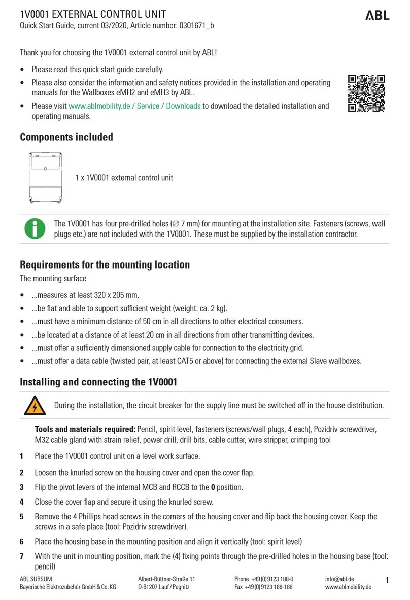
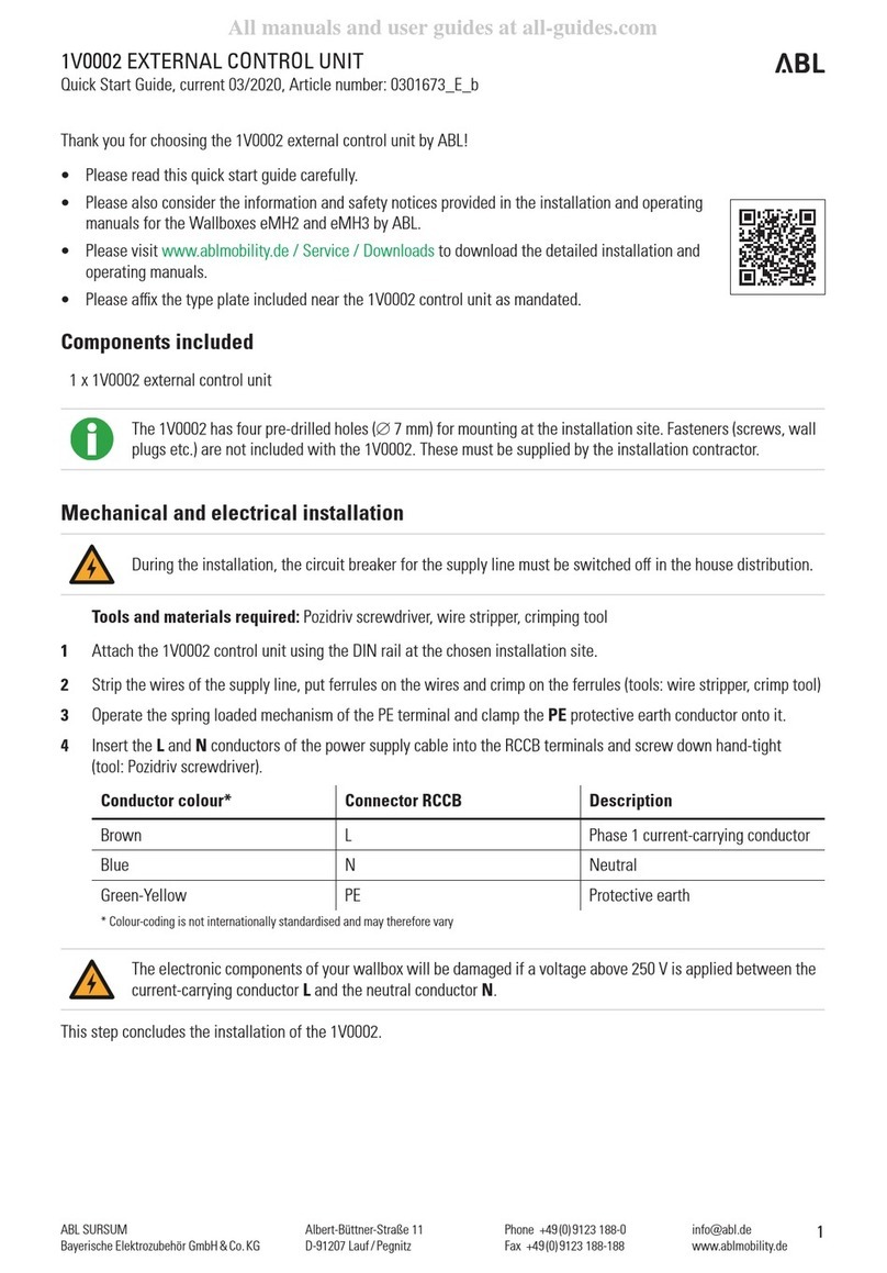
ABL 1V0002 User manual

www.ablmobility.de
Albert-Büttner-Straße 11
D-91207 Lauf / Pegnitz
Phone +49 (0) 9123 188-0
Fax +49 (0) 9123 188-188
ABL SURSUM
Bayerische Elektrozubehör GmbH & Co. KG
1
1V0002 EXTERNAL CONTROL UNIT
Quick Start Guide, current 03/2020, Article number: 0301673_E_b
Thank you for choosing the 1V0002 external control unit by ABL!
• Please read this quick start guide carefully.
• Please also consider the information and safety notices provided in the installation and operating
manuals for the Wallboxes eMH2 and eMH3 by ABL.
• Please visit www.ablmobility.de / Service / Downloads to download the detailed installation and
operating manuals.
• Please ax the type plate included near the 1V0002 control unit as mandated.
Components included
1 x 1V0002 external control unit
The 1V0002 has four pre-drilled holes (∅7mm) for mounting at the installation site. Fasteners (screws, wall
plugs etc.) are not included with the 1V0002. These must be supplied by the installation contractor.
Mechanical and electrical installation
During the installation, the circuit breaker for the supply line must be switched o in the house distribution.
Tools and materials required: Pozidriv screwdriver, wire stripper, crimping tool
1 Attach the 1V0002 control unit using the DIN rail at the chosen installation site.
2 Strip the wires of the supply line, put ferrules on the wires and crimp on the ferrules (tools: wire stripper, crimp tool)
3 Operate the spring loaded mechanism of the PE terminal and clamp the PE protective earth conductor onto it.
4 Insert the Land Nconductors of the power supply cable into the RCCB terminals and screw down hand-tight
(tool: Pozidriv screwdriver).
Conductor colour* Connector RCCB Description
Brown L Phase 1 current-carrying conductor
Blue N Neutral
Green-Yellow PE Protective earth
* Colour-coding is not internationally standardised and may therefore vary
The electronic components of your wallbox will be damaged if a voltage above 250 V is applied between the
current-carrying conductor Land the neutral conductor N.
This step concludes the installation of the 1V0002.

www.ablmobility.de
Albert-Büttner-Straße 11
D-91207 Lauf / Pegnitz
Phone +49 (0) 9123 188-0
Fax +49 (0) 9123 188-188
ABL SURSUM
Bayerische Elektrozubehör GmbH & Co. KG
Connecting master/slave communications and commissioning
Tools and materials required: M32 cable gland with strain relief, cable cutters, wire stripper, data cable (twist-
ed pair, at least CAT5 or above), Pozidriv screwdriver, Voltmeter
The circuit breaker in the domestic power distribution must remain switched o until step 5.
1 Cut the data cable to the required length for connecting to the daisy chain circuit board and strip as required (tools:
cable cutter, wire stripper).
2 Strip the wire strands of the data cable.
3 Clamp the wires of the data cable onto the left or right hand side terminal block of the daisy chain circuit board.
Wire strand colour*
(recommended) Connection coding Description
White-Orange METER – B DATA energy meter
Orange METER – M GND energy meter
White-Green METER – A DATA energy meter
Green CONTROL – B DATA control unit
White-Blue CONTROL – M GND control unit
Blue CONTROL – A DATA control unit
* Colour coding according to EIA/TIA-T568B, variations possible
4 Insert the data cable into the first Slave wallbox and clamp in onto the left or right hand side terminal block of its
daisy chain circuit board (see the detailed installation and operating manual for the wallbox).
For correct functioning, the colour coding between the individual data cable wire strands and the daisy chain
terminal blocks must be strictly observed in all master/slave units!
Only the first Slave wallbox will be connected directly to the 1V0002. Each additional slave will be connect-
ed to the Slave wallbox that precedes it.
5 Switch on the circuit breaker for the power supply to the 1V0002 in the domestic power distribution and measure
the voltage at the RCCB if required (tool: voltmeter).
6 Flip the pivot levers of the internal MCB and RCCB to the Iposition.
This completes the commissioning of the 1V0002 control unit.
Setting up master/slave communications
Tools and materials required: Computer, Ethernet cables with RJ45 plug-in connectors
In order to proceed with configuration, the 1V0002 must be connected to the power supply. Special caution
is therefore required due to the presence of electrical voltages!
1 Use the Ethernet cable to connect the computer to the RJ45 socket on the centrally located SBC circuit board of the
1V0002.
2 On the computer, open the browser and enter the address http://169.254.1.1:8300/.

www.ablmobility.de
Albert-Büttner-Straße 11
D-91207 Lauf / Pegnitz
Phone +49 (0) 9123 188-0
Fax +49 (0) 9123 188-188
ABL SURSUM
Bayerische Elektrozubehör GmbH & Co. KG
3
In case of connection errors, check the network settings of the computer and adjust them as follows:
• Network: 169.254.0.0
• Subnet mask: 255.255.0.0
• Address: 169.254.1.2
3 The online administration interface opens in the browser. The following functions are available using the tabs:
Tab Description
Overview • Checking the status of all recognised master and slave model variants
• Checking the system software version
Configuration • Checking information about the 1V0002 control unit, the backend and OCPP
• Editing backend operator details (only when changing backend operator)
• Assigning backend ID to control unit
Devices • Checking the system's total connected load
• Checking the maximum connected load for each Slave wallbox
Products • Registering additional Slave wallboxes in the system
• Editing 1V0002 properties
Certificates • Checking backend operator certificates
Diagnostic
Functions
• Checking version and status information for all communicating components in the
system
Logs • Checking logged access to the communicating components in the system
Maintenance • Carrying out a restart (software and/or hardware)
• Updating the system software
• Running system diagnostics
4 Disconnect the Ethernet cable from the RJ45 sockets in both the 1V0002 and the computer.
The 1V0002 control unit is now configured as master to control the Slave wallboxes.
Subject to change: All performance characteristics, technical and other specifications are subject to change without prior notice.

www.ablmobility.de
Albert-Büttner-Straße 11
D-91207 Lauf / Pegnitz
Phone +49 (0) 9123 188-0
Fax +49 (0) 9123 188-188
ABL SURSUM
Bayerische Elektrozubehör GmbH & Co. KG
Other ABL Control Unit manuals
Popular Control Unit manuals by other brands

Advantech
Advantech PCM-2610B Startup manual

White Rodgers
White Rodgers 758-1 installation instructions

Ingersoll
Ingersoll X8I Quick setup guide

Circuit Slices
Circuit Slices Ring+VCA quick start guide

Dungs
Dungs GasMultiBloc MB-D B07 Series instructions

Festo
Festo MS6 SV E 10V24 Series operating instructions