ABS ABSFBM-50 User manual

OWNER’S MANUAL
ABSFBM-50
(Spiral Mixer)

CONTENTS
1
Introduction••••••••••••••••••••••••••••••••••••••••••••••••••••••••••••••••••••••••••(2)
Installation & Commissioning•••••••••••••••••••••••••••••••••••••••••••••••••••(3)
Operation•••••••••••••••••••••••••••••••••••••••••••••••••••••••••••••••••••••••••••••(4)
Caution••••••••••••••••••••••••••••••••••••••••••••••••••••••••••••••••••••••••••••••••(8)
Cleaning & Maintenance••••••••••••••••••••••••••••••••••••••••••••••••••••••••••(9)
Trouble Shooting••••••••••••••••••••••••••••••••••••••••••••••••••••••••••••••••••(10)
Parts List••••••••••••••••••••••••••••••••••••••••••••••••••••••••••••••••••••••••••••(12)
Wiring Diagram••••••••••••••••••••••••••••••••••••••••••••••••••••••••••••••••••••(20)

INTRODUCTION
2
Introduction
The ABSFBM-50 is a Spiral Mixer with a two-timer control panel and a
single motor that drives both the hook and the bowl. The hook and bowl are
made of stainless steel for long life and ease of cleaning. The full bowl
cover keeps flour dust down and protects the operator from the hook while
operating.
Owners and operators should carefully read and familiarize themselves
with this entire manual before attempting to operate or service this machine.
Complying with this manual will ensure years of safe and trouble-free
operation.
All of the information, illustrations and specifications contained in this
manual are based on the latest product information available at the time of
printing. American Baking Systems reserves the right to make changes at
any time without notice. If questions arise during the operation or servicing,
please contact us before proceeding.
Specifications

INSTALLATION AND COMMISSIONING
3
Installation
The machine is ready for installation. After uncrating your spiral mixer,
inspect the machine for any damage that might have occurred during
shipment. Report any damage to us before proceeding. Never attempt to
operate this mixer with damaged parts.
1).Position the mixer in its appropriate working position, the mixer must be
installed on a horizontal and solid floor.
2).Adjust the mixer feet to ensure that the mixer is level, and seat it firmly
on all four corners. Ensure that no wheels touch the ground. The axles
are not designed to support the unit while mixing.
3).Connect the correct power supply to the machine as indicated on the
machine nameplate.
Commissioning
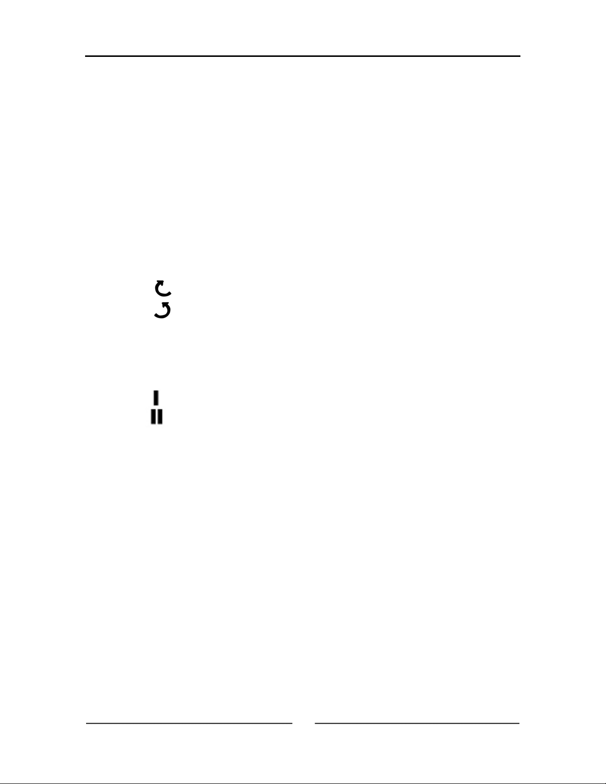
1).Start the mixer to check the direction of rotation of the kneading spiral
and the bowl. When viewed from above, both kneading spiral and bowl
should rotate clockwise. The arrow on the bowl indicates the correct
direction of the bowl. If the rotation direction is incorrect, swap two
phases in the plug (white and black wires) to reverse the rotation
direction.
2).Test the function of the safety emergency stop button. The machine
must stop immediately when you press this button.
3).Test the function of the limit switch for the bowl safety guard. When the
guard is lifted, the machine must stop immediately.

OPERATION
4
Control Panel
1.Timers
On top of the control panel, there are two timers: Timer I is for slow speed;
Timer II is for fast speed. Each timer has three digits.
The unit of A and B are minutes and C is 10 seconds, (for example: 0.1 is
10 seconds, 0.2 is 20 seconds.)
The timers are set by and buttons. Press button to
increase the time, the maximum set time is 20 minutes. After 20 minutes,
the timer starts from 0 minutes again. Press button for the opposite
operation.
When the spiral mixer is switched ON, timers will show the set time. The
timer will only work when mixer is in AUTO mode. The timer will start
automatically when the (ON) button is pressed. The slow speed timer will
run first and then the fast speed timer second, the mixer stops until timer
reaches 0 minute.
When the spiral mixer safety guard is lifted, the timer will stop with the mixer
and resume when the guard is lowed down and the ON button is pressed.
When the OFF button is pressed, the timers will return to the set time.

OPERATION
5
2.Indication lights
Indication lights indicate the running state of the spiral mixer:
A). AUTO/MANUAL lights:
When “AUTO” lamp lights up, spiral mixer is inAUTO operation.
When “MANU” lamp lights up, spiral mixer is in MANUAL operation.
B). Bowl direction lights:
As this Mixer only has one motor, the hook and the bowl will rotate in
the same direction.
When lamp lights up, the bowl and hook are in forward direction.
When lamp lights up, the bowl and hook are in reverse direction.
C).Mixer speed lights:
As the Mixer only has one motor, when you change the speed of the
hook, the speed of the bowl will be also changed.
When lamp lights up, spiral mixer is in the slow speed state.
When lamp lights up, spiral mixer is in the fast speed state.
D).Bowl inching light:
When “INCH” lamp lights up, spiral mixer is in manual inch mode.
E). On model light:
When “ON” lamp lights up, spiral mixer is in mixing mode.
F). Light:
When “O.L.” (OVERLOAD) lamp lights up, the overload relay is on. It
inform you that the mixer is overload, please switch off the mixer and
decrease the mixing weight and restart the machine again.
G).Stop mode light:
When “STOP” lamp lights up, safety cover has been raised during
mixing mode.

OPERATION
6
3.Function keys
AUTO / MANUAL selection Speed selection button
Bowl direction selection Inching button
Start button Stop button
Operation Preparation
Check the mixing bowl is clear of all foreign objects, all control switches are
off and operation area should be clear of bystanders.
The electrical cord should be in the appropriate socket and power turned
on.
Safety guard should be raised and pushed back fully against stops to avoid
injury. The mixer has safety interlocks to prevent mixer operation when the
safety guard is lifted.
Weigh out and load ingredients into bowl according to recipie.
Operation Steps
1.Auto operation
A). Press buttons below timer to set the desired time for
slow mixing speed.
B). Press buttons below timer to set the desired time for
fast mixing speed.
C).Press button until the “AUTO” lamp lights up.
D).Press button until the lamp lights up.
E). Press button to start machine.

OPERATION
7
2.Manual operation
A). Press button until the “MANU” lamp lights up.
B). Press buttons to select the desired direction.
C).Press button to start.
D).Press button when you want to stop the operation.
The timer will stop functioning under manual operation.
The mixer will always start with slow speed even if you have selected fast
speed to start. When the mixer is running at slow speed, you can press
button to change mixer into fast speed while in manual mode.
3.Control Buttons
When digital panel is damaged, the mixer can be operated by manual
switch located at left side of top cover. You can select slow speed or fast
speed manually without timer.
A). Press “ON” to start the machine
B). “1” means slow speed, “2” means
fast speed.
You can stop the machine by pressing
the emergency stop button or lifting the
safety guard.

CAUTION
8
1.Use the machine with great care and never be distracted.
2.Do not wear loose fitting clothes or clothing with wide or open sleeves.
3.Do not remove, cover or alter the warning stickers or machine safety
covers placed on the machine body.
4.Use machine only for what it was intended.
5.Do not set dough knives or scrapers atop machine, they could fall in
during operation and ruin the machine or injure the operator.
6.Do not use the machine with temporary electrical connections or
non-insulated cables.
7.Periodically check the state of the power cord and the cable clamp on the
machine body, replace it if necessary by an authorized service provider.
8.Discontinue use of the machine if there are broken or missing covers, a
damaged cord, or loud or odd noises coming from the machine.
9.Before cleaning or carrying out maintenance, isolate the machine from
the power supply first.
10. For all extraordinary maintenance, consult with the manufacturer or
authorized personnel.
11. Never insert hands or other objects into the bowl when the machine is
in operation. Keep hands and clothing away from bowl rollers while
bowl is turning.

CLEANING AND MAINTENANCE
9
1.Brush off all external surfaces. Use a soft brush and work from the top to
the bottom.
2.Remove all old dough using a plastic scraper.
3.Scrape the mixing bowl, the breaker bar, the dough spiral, under the bowl
cover inside the mixing bowl, and behind the mixing bowl.
4.Wipe all surfaces with warm water.
5.Apply a detergent/sanitizer and leave on all surface.
6.Scrub to loosen and remove residues.
7.Rinse the bowl and dough spiral mixer tool thoroughly with hot water on a
damp rag. DO NOT POWER WASH OR HOSE OFF MACHINE!
8.Remove excess moisture with clean towels. Dry all surfaces.

TROUBLE SHOOTING
1
0
Fault Possible Cause Remedy
The mixer does not
operate /start.
Not plugged into the
socket at main switch.
The main switch is “off”.
The bowl safety guard is
open.
The mixer overload has
been activated.
Stop button is still locked
in the down position.
Plug in and switch
on.
Turn on.
Place it down
position.
Contact supervisor /
service agent.
Release by rotating
and pulling.
The mixer starts and
then immediately
stops.
Both high and low speed
timers are set to zero.
The mixer overload has
been activated.
Fuse overload at the
power board.
Reset mix cycle on
both timers.
Contact supervisor /
service agent.
Contact supervisor /
service agent.
The mixer labors under
load.
Dough too stiff / tight.
Machine malfunction.
Review and adjust
dough consistency;
add more liquid.
Contact supervisor /
Service agent.
The mixer moves or
rocks during operation.
Floor not level or the
adjustable feet are
located incorrectly.
Re-adjust level and
stabilize with
adjustable foot.
Excessive flour dust
coming from mixer. First speed timer set too
short. Extend first speed
mix / blending cycle.
The mixer bowl and
dough hook operate in
the wrong direction.
Inserting the mixer plug
into the incorrect socket
after cleaning.
Relocating the mixer in
another position after
maintenance.
Return to correct
position.
Consult authorized
electrical service to
rewire plug.

TROUBLE SHOOTING
1
1
Fault Possible Cause Remedy
The mixer does not
stop Electrical / mechanical
malfunction.
Switch off power at
main switch. Isolate
mixer by removing
wall plug.
Attach danger tag to
machine.
Contact service
agent.
Bread dough too soft.
Excessive water used in
dough (human error).
Incorrectly metered /
measured through water
meter (equipment error).
Over-mixed dough
Review recipe and
adjust dough
consistency.
Contact authorized
service agent.
Review /check
/change mix cycle.
Final dough temperature
too hot.
Water temperature too
hot.
Dough mixed too long.
Reduce water
temperature.
Shorten mix cycle.
Final dough temperature
too cold.
Water temperature too
cold.
Dough mixed too shot.
Increase water
temperature.
Lengthen mix time.
Dough is difficult to
remove from the mixing
bowl.
Dough left in bowl too
long.
Dough too soft.
Dough over-mixed.
Remove from bowl
earlier.
Refer-dough too
soft.
Run food grade oil
between dough and
bowl at the end of
mix cycle to stop
dough sticking.

Parts List
2
0

Parts List
2
1

Parts List
2
2

Parts List
2
3

Parts List
2
4

Parts List
2
5
Parts
Number Parts Code Parts Name Specification
16BYQJBK63-1 Transformer 220V/380V-26V/110V(2A)
16BYQJBK63-18 Transformer 400V-110V/26V
16BYQJBK63-16 Transformer O-208V-220V//110V(13VA)-26V(50VA)
SM50001
16BYQJBK63-2 Transformer 415V-80%220V/20%26V
SM50002 16LSLCI-18 Mechanical
Connector
SM50003 16JDQRHN10A-3 Thermal Relay RHN-10A 5.5-8.5A
SM50004 16JDQRHN10A-4 Thermal Relay RHN-10A 8.5-12.5A
SM50005 16JDQPYF-08 Relay Seat
SM50006 16JDQPYF-14 Relay Seat
SM50007 16JDQMY4-24V Relay
SM50008 16JDQMY2-24V Relay
SM50009 16JCQCN16-1 Contactor CU-16 3A1b 24V/50HZ
SM50010 16BXSG111B Fuse Cover
SM50011 16BXSZD Fuse Seat
SM50012 15ZCL6305VV Bearing 6305ZZ 2RS
SM50013 15ZCL6206VV Bearing 62062RS UBC
SM50014 14M371-01 Spacer for Main
Shaft
SM50015 15YFL35*62*7 Oil Seal for Main
Shaft 35*62*7
SM50016 14M370-01 Main Shaft
SM50017 16KGLMEA9112G Microswitch
SM50018 15PDLA42 Belt 1PCS
SM50019 15PDL1030 Belt 7M-1030 4PCS
SM50020 15PDL825 Belt 7M-825,3PCS
SM50021 11M870-01 Machine Rear
Cover 1.5T*400*542 SPCC
SM50022 16MBOMX-005 Digital Touch
Control Panel Two-Timer Model
SM50023 16KGLZB5-AD3 Selector Switch
16KGLBE101 Cover for Manual
Switch
SM50024 16KGLZA-BD3 Manual Switch
SM50025 16KGLZA2-BS54 Emergency-Stop
Switch
SM50026 16KGLOT25ET3 Power Switch
SM50027 13M444-01-01 Machine Top
Cover
SM50028 11M750-110 Bowl Safety Grid
SM50029 15ZCL6200VV Bearing
SM50030 14M850-01 Bowl Roller Bolt
SM50031 14M840-01 Bowl Roller

Parts List
2
6
SM50032 11M620-01 Mixing Bowl
SM50033 13M801-06 Bowl Cover
SM50034 13M802-06 Bowl Cover
SM50035 13M640-01 Clamping Block
SM50036 13M650-10 Center Pillar
14M630-01 Dough Hook
SM50037 14M630-01S Dough Hook Stainless Steel
SM50038 15ZCL6207VV Bearing 62072RS NACHI
SM50039 15ZCL6010VV Bearing 60102RS NACHI
SM50040 16MDL50-4-02 Motor B3YD112M-4/8
YD112M-8/4 380V-50HZ-3PH 1.5/3KW
SM50041 15ZCLUCFL206 Bearing (with seat) UCFL206G FYH
SM50042 14M190-01 Transmission Shaft
SM50043 15BSLHY01 Outrigger Screw HY8314.4 B-M16*63
SM50044 14D9016150-01 Foot Pad
SM50045 15LZL5 Rear Wheel
SM50046 14M240-01 Sprocket Wheel for
Transmission Shaft
SM50047 14M580-01 Sprocket Wheel for
Rotating Plate
15LTL86 Chain 5/8*86
15LTJ5/8A Connector for
Chain
SM50048
15LTJ5/8B Connector for
Chain
SM50049 15ZCL51104 Bearing
SM50050 15ZCL6002VV Bearing
SM50051 15LZLH3 Front Castor
SM50052 14M325-01A Motor Pulley FOR 50HZ
SM50053 14M250-01 Transmission Shaft
Pulley
SM50054 14M380-01 Main Shaft Pulley
SM50055 14M260-01 Bottom Pulley for
Transmission Shaft
SM50056 14M811-10 Bowl
Cover Bracket RIGHT
SM50057 13M770-01 Bowl Cover
SM50058 13M830-01 Bowl Roller Seat
SM50059 14M220-01 Bearing Housing
for Transmission
Shaft
SM50060 14M142-01 Outrigger Bolt
SM50061 14M140-06 Support Strut
SM50062 15ZCL6203VV Bearing
SM50063 14M180-01 Shaft for Rear
Wheel

Parts List
2
7
SM50064 14M600-01 Lock Nut
SM50065 14M560-01 Rotating Plate
SM50066 14M530-01 Bearing Housing
SM50067 14M160-03 Seat for Front
Castor
SM50068 14M150-03 Bracket for Front
Castor
SM50069 14M170-02 Shaft for Front
Castor
SM50070 14M670-03 Adjusting Wheel
Mount Clip LEFT
SM50071 14M680-03 Adjusting Wheel
Mount Clip RIGHT
SM50072 14M461-01 Fixing Piece for
Top Cover
SM50073 14M471-01 Fixing Piece for
Top Cover
SM50074 16JWB280301 End Plate for
Electrical Wire
SM50075 16DZP280101 Connector
SM50076 12M491-01 Plate for Control
Panel 2t*400*420 SPCC
SM50077 12M492-50 Fixing Piece for
Control Panel 2t*64*250
SM50078 12M472-02 Fixing Piece for
Control Panel 2T*386*78 SPCC
SM50079 11M880-01 Machine Side
Cover 1.2T*142*242 SPCC
SM50080 14M780-05A Safety Grid Stoper
SM50081 14M340-01 Bearing Housing
for Main Shaft
SM50082 14M700-02 Adjusting Wheel for
Bowl Cover
SM50083 12M730-04 Bottom Plate for
Microswitch M730-04 SPCC-2t*60*81
SM50084 14M710-02 Adjusting Wheel for
Microswitch
SM50085 15ZCL6202VV Bearing
SM50086 15ZCL6006VV Bearing
SM50087 14M200-01 Bush for
Transmission Shaft
SM50088 14M230-01 Brass Bolt
SM50089 14M845-01 Watertight Cover
SM50090 12M860-02 Fixing Piece SUS304 2t*25*49
SM50091 14D9016150-03 Bushing
SM50092 2PDS20 Stainless Steel
Gasket Ф20
SM50093 14M810-10 Bowl Cover Bracket LEFT
SM50094 16MKCNI-18 Interlock
Table of contents
Other ABS Mixer manuals
Popular Mixer manuals by other brands

Kushlan
Kushlan Industrial Portable Tripod Mixer Operating instructions & parts manual

Kooper
Kooper 5902496 manual

Meec tools
Meec tools 009-016 operating instructions

Westinghouse
Westinghouse WHSM03K instruction manual

Teka
Teka THZ 375 operating instructions

Linear Technology
Linear Technology 642 quick start guide