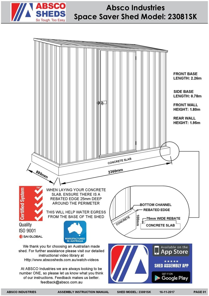
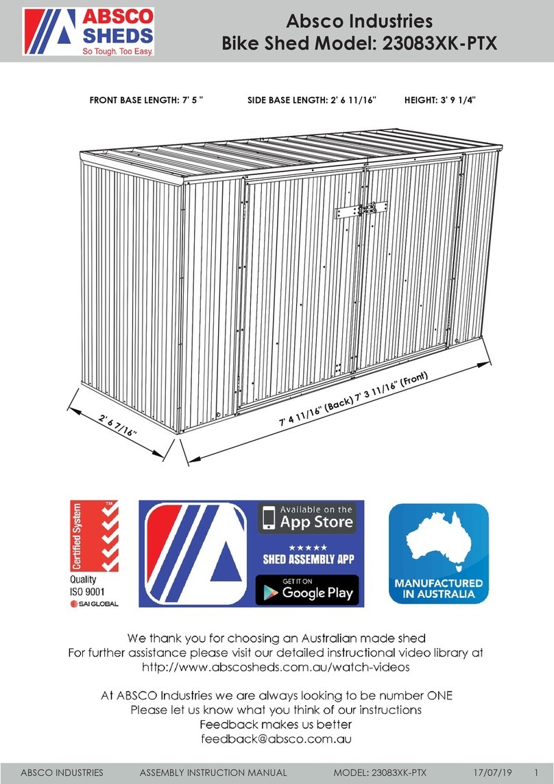
ABSCO SHEDS ADGAZEBO63 User manual

Absco Industries Assembly Instruction Manual
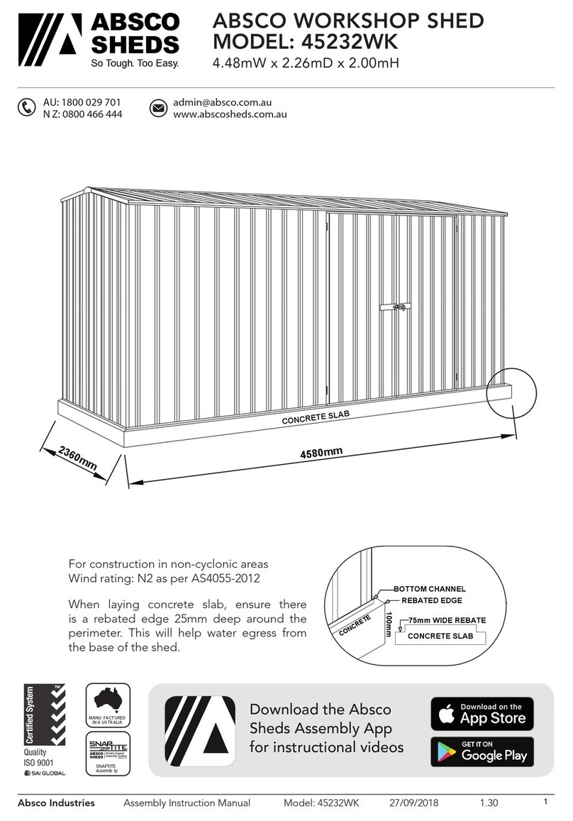
ABSCO SIGNATURE GAZEBO
MODEL: ADGAZEBO63
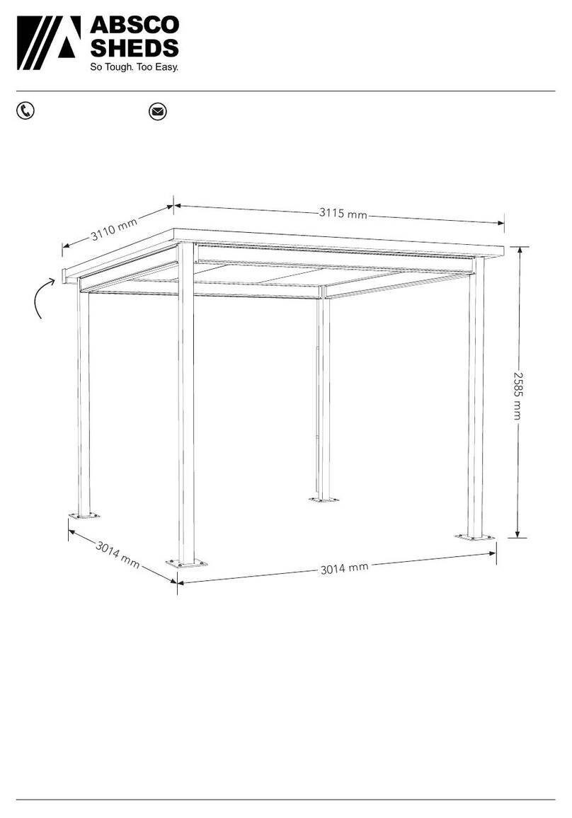
6.12m W x 3.11m D x 2.60m H
Model: ADGAZEBO63 4/12/23 1.00 1
AU: 1800 029 701
N Z: 0800 466 444
www.abscosheds.com.au
For construction in non-cyclonic areas
Wind rating: N3 as per AS4055-2021.
If you require a higher wind rating please contact
NOTE - Concrete slab must be a minimum of
100mm thick, 20 MPa concrete reinforced with
SL72 mesh and extend for the full area covered by
the structure.
3115 mm
3014 mm
2585 mm
6021 mm
6120 mm
FRONT
2^fall
to rear
o

Absco Industries Assembly Instruction Manual
ABSCO SIGNATURE GAZEBO
MODEL: ADGAZEBO63
6.12m W x 3.11m D x 2.60m H
Model: ADGAZEBO63 4/12/23 1.00 2
Safety
Some parts may have sharp edges. It is
recommended to wear gloves when handling
items and safety glasses when drilling holes.
Sensible shoes are highly recommended.
Minimum two people are required to easily lift
and align assemblies.
Consider the weather and do not build in windy
conditions.
If the structure must be left for a period of time
uncompleted it must be made safe to prevent
damage.
TOOLS REQUIRED
Use as a guide, other tools/equipment may be suitable. Safely work within your ability.
Please wear recommended
PPE for any tool used during
construction
!
General
Read through these instructions in detail to gain
a thorough understanding of assembly methods
and associated details.
Unpack and carefully identify and check off all the
parts against the parts described and illustrated
on “Components List” page.
If you are missing anything do not begin, contact
Absco.
Site Prep
The structure shall be erected on top of suitable
foundations and anchored down appropriately.
The site for the structure must be level. An uneven
surface may result in misalignment of parts.
Region specific: If required, you have approval for
the structure. If unsure, seek advice from relevant
local authorities.
• Sheet metal locking pliers
• 4mm drill bit
• 5/16” & 3/8” nut setter
• 12mm masonry drill bit
• Chuck drill
• Impact drill driver
• Hammer drill
• 8m tape measure
• Caulking gun
• 16mm socket
• 1.8m ladder (2 required)
• Visegrips or clamps
• Pop riveter
• Stanley knife
• Masking tape
• Spirit level
• Marker
• Ruler
• Square
• String line
• 70mm hole saw
• Tin snips
IMPORTANT INFO - READ BEFORE CONSTRUCTION BEGINS

Absco Industries Assembly Instruction Manual
ABSCO SIGNATURE GAZEBO
MODEL: ADGAZEBO63
6.12m W x 3.11m D x 2.60m H
Model: ADGAZEBO63 4/12/23 1.00 3
Beam End
Cap
Gutter
Gutter
Stop end
Dropper 80 to
90 mm
Adapter
Clip
Check off all components, parts shown are not to scale.
FASTENER PACKS
COMPONENT LIST
AD1 6
QTY CHECK SB1 2
QTY CHECK SB2 2
QTY CHECK
2
QTY CHECK
TR36 2
QTY CHECK
TR37 2
QTY CHECK
TR35
3020 mm
3115 mm
Downpipe
80 mm
RWG
21 1
QTY CHECK
2925 mm
2680 mm
5680 mm
3045 mm
3140 mm
3105 mm
1
QTY CHECK
TU
8
QTY CHECK
BK3
1
QTY CHECK
2
QTY CHECK
1
QTY CHECK
2
QTY CHECK
2
QTY CHECK
200
QTY CHECK
FAST100 200
QTY CHECK
FAST101 200
QTY CHECK
FAST102
16
QTY CHECK
FAST103 48
QTY CHECK
FAST104
RWG
23
RWG
22
RWG
24 RWG
29 1
QTY CHECK
RWG
27
RWG
25
Gutter
Bracket
7
QTY CHECK
RWG
26
High side
Flashing Foam
gasket
End
Flashing
Touch-up
Paint
Water proof
Sealant
Insulated
panel
Z Flashing
6
QTY CHECK
RWG
28
2490 mm
2400 mm
2
QTY CHECK
PT3 2
QTY CHECK
PT4
Short
posts
Tall
posts
End
Beam
Side
Beam

Absco Industries Assembly Instruction Manual
ABSCO SIGNATURE GAZEBO
MODEL: ADGAZEBO63
6.12m W x 3.11m D x 2.60m H
Model: ADGAZEBO63 4/12/23 1.00 4
POSTS
BK3
BK3
1. Take any post and a BK3 bracket.
Orientate the bracket as shown and align so it’s
flush with the end and side of the post.
2. Fasten using four FAST100 tek screws and
5/16” nut setter.
Make sure screws are inset 20 mm from the
edges of bracket for beam clearance.
To keep the parts aligned while fastening use a
clamp or visegrips.
3. Carefully roll the post to the side shown.
4. Take another BK3 bracket and align so it’s
flush with the end and side of the post as shown.
5. As before, fasten using four FAST100 tek
screws.
Make sure they’re inset 20 mm from the sides.
6. Repeat these steps for all posts.

Absco Industries Assembly Instruction Manual
ABSCO SIGNATURE GAZEBO
MODEL: ADGAZEBO63
6.12m W x 3.11m D x 2.60m H
Model: ADGAZEBO63 4/12/23 1.00 5
POST LOCATIONS
ANCHORING
Use a chalk line, or equivalent, to mark nominal
outside dimensions onto foundation.
The diagonal measurement will confirm
squareness.
NOTE:
For illustrative purposes the gutter will be at the
rear for the rest of this manual.
Drill the holes for the anchors using the post
baseplate as a template.
Use a hammer drill with a 12mm diameter
masonry drill bit drill to a depth of 100mm
Fasten to foundations with four concrete screws
FAST103 per post using a 16mm socket.
NOTE: Uneven foundations will cause posts to
pull away from vertical.
Position posts in the corners.
• Shorter PT3 posts to the gutter side.
• Taller posts PT4 to the other side.
• Make sure the faces with the brackets are all
inward.
These internal dimensions can be used to
confirm alignment.
FRONT
FRONT
6021
5521
6066
67333014
2514

Absco Industries Assembly Instruction Manual
ABSCO SIGNATURE GAZEBO
MODEL: ADGAZEBO63
6.12m W x 3.11m D x 2.60m H
Model: ADGAZEBO63 4/12/23 1.00 6
Rear beam
FITTING THE SHURELOCK BEAMS
NOTE: Beam orientation is important to prevent
water entry.
Orientate the beam so the exterior face has the
overlap to the top.
1. Safely lift and place a longer SB2 beam inside
the taller post brackets BK3 as shown.
Overlap to
top
Overlap to
bottom
INTERIOR
EXTERIOR
CL
4. Safely lift and place the first shorter beam SB1
inside the post brackets BK3 as shown.
5. Make sure the ends of the beam are as far
as they can go into the brackets, there will be a
small gap at the high-side due to angle.
Fasten each end with four FAST100 tek screws
as before.
6. Repeat these steps for the other SB1 beam
2. Make sure the ends of the beam are all the
way into the brackets and fasten each end with
four FAST100 tek screws.
These are visible screws so take time to position
them on the centreline of the BK3 bracket and
inset equally from the top and bottom.
3. Repeat these steps for the other long beam
SB2 before proceeding to step 4.
On the exterior side of the rear beam that will
get the gutter, only put in the lower teks for now.
0. Remove the protective plastic coating from
the outside of the beam.
Shorter posts
Front

Absco Industries Assembly Instruction Manual
ABSCO SIGNATURE GAZEBO
MODEL: ADGAZEBO63
6.12m W x 3.11m D x 2.60m H
Model: ADGAZEBO63 4/12/23 1.00 7
1. Place one Z flashing TR35 along the lower side
beam as pictured.
Align to be flush with the exterior of the beam.
2. Overhang the end of the beam by 125 mm.
3. Fasten flashing to top of beam with 4 evenly
spaced pop rivets FAST102.
4. Fasten the second Z flashing in the same
manner.
ATTACH Z FLASHING
ROOF PANELS
FLUSH
Front
Rear
125
1
3
2
FLUSH
REAR VIEW - Aligning the first panel
5
‘Z’ flashing
Rear beam
A. Check the foam core is flush with the top and
bottom skins. If it bulges out, safely trim flush with
a Stanley knife.
B. Check if the steel bottom skin corner is bent
down below the bottom face. Bend it up with
pliers.
C. To increase weather protection turn up the
pans 15 degrees with a turn up/down tool or
equivalent as shown. (Front end only)
Familiarize yourself with the weight and orientation
of the AD1 panel before lifting.
The panel end with ‘top skin’ overhang & sticker
must go to the low side beam.
The ‘bottom skin’ has a protective plastic coating,
this can be peeled off just before lifting.
Remember to lift and place do not slide, this can
scratch the panel.
1. Safely position the first panel on top of the
frame - all the way to the end shown.
The steel ‘top skin’ will sit over the rear flashing.
2. Adjust so it’s butted up against the rear trim
and the side of the ‘top skin’ is flush with the end
of the flashing.
15o
C

Absco Industries Assembly Instruction Manual
ABSCO SIGNATURE GAZEBO
MODEL: ADGAZEBO63
6.12m W x 3.11m D x 2.60m H
Model: ADGAZEBO63 4/12/23 1.00 8
3. On the middle rib, fasten panel to low side
beam with a tek 14 x 125 mm FAST104.
Don’t over-tighten and crush the panel.
For further screw position detail see Fastening
layout below.
4. Check for consistent overhang along end beam
- adjust if required.
Fasten with a tek 14 x 125 mm FAST104 at the
midpoint of side beam - in the sheet pan.
5. On the middle rib, fasten to front beam with
another tek 14 x 125 mm FAST104.
Fixed panel
A. Overlap rib
B. Press here
Complete
Next panel
‘Bottom skin’ male &
female features align
FRONT VIEW - Laying the roof panels
ROOF PANELS
Front
Rear
4
3
5
Side beam
TOP VIEW - Fastening layout 6. Fasten roof panels to beams with
a tek 14 x 125 mm FAST104 at the
remaining positions.
NOTE: rib fixed to centreline of beam
unless noted otherwise.
NOTE: 3, 4& 5are the screws done
earlier.
Don’t over tighten and crush the panel.
7. Use shorter tek screws with neoprene
washers FAST101 at the locations
marked with ‘x’ where the ‘top skins’
overlap.
3
5
4
x
x
x
x
x
x
x
x
x
x
First
panel
Last
panel

Absco Industries Assembly Instruction Manual
ABSCO SIGNATURE GAZEBO
MODEL: ADGAZEBO63
6.12m W x 3.11m D x 2.60m H
Model: ADGAZEBO63 4/12/23 1.00 9
NOTE:
Leave the protective plastic on TR36 flashing until
fastening, It’s good to mark on.
Do one TR36 as pictured - the other TR36 is the
same but ‘mirrored’.
1. Mark out and cut away 15mm from the top
and bottom sides using tinsnips (offcuts shown in
grey).
2. You’ll be left with a tab as shown. Use “Sheet
Metal Locking Pliers” to easily fold it 90 degrees.
3. Check fit by placing flashing along the edge of
roof panel.
• Bent tab hard up against end.
• Top face sits on two sheet ribs.
• Bottom face covers the Z flashing.
15
90o
0. TR36 flashing will overhang roof panel at the
rear and we’ll need to trim to make the gutter fit
later.
NOTE: If the flashing is the same length as the
roof panel you don’t need to trim the top.
1. Mark off where ‘top skin’ end is against the top
side of the TR36 flashing.
Then continue 30mm down the side.
2. Mark off where the rear ‘Z’ flashing is against
the bottom side of the flashing.
Then continue 40mm up the side.
3. On the side mark a line to join these points as
shown.
4. Take the flashing down off the roof and trim
using tinsnips (offcuts shown in grey).
UNDERSIDE VIEW - Beams not shown.
12
30
40
0
SIDE FLASHING - FRONT DETAIL
SIDE FLASHING - REAR DETAIL

Absco Industries Assembly Instruction Manual
ABSCO SIGNATURE GAZEBO
MODEL: ADGAZEBO63
6.12m W x 3.11m D x 2.60m H
Model: ADGAZEBO63 4/12/23 1.00 10
5. Refit the flashing, and fasten using pop rivets
FAST102 at the locations shown.
Only at the low side, on top, use teks with
neoprene washers FAST101.
HIGH SIDE UNDERSIDE VIEW
FRONT TOP VIEW
6. Repeat these steps for
the other end flashing. Just
remember to make the
mirrored version.
FRONT & REAR FLASHING
LOW SIDE UNDERSIDE
VIEW
1. Starting at the front end of the structure,
take one TR37 flashing and place over the front
flashing and roof panels as shown.
2. Take the second TR37 flashing and place
alongside, butted against the first & trim so it
finishes at the rear flashing.
3. Fasten with pop rivets FAST102 along the
underside are shown.
Fasten with tek screws with neoprene washers
FAST101 along the top.
To increase weather protection do the following.
A. Turn up pans of sheet 15 degrees using “Sheet
Metal Locking Pliers”
B. Installing foam gaskets RWG28 within 90mm
of the edge.
Some trimming may be required to fit at ends.
Apply silicone to the face that sits in the pan.
UNDERSIDE VIEW
TR37
#1
TR37
#2
FRONT EDGE
FRONT FLASHING

Absco Industries Assembly Instruction Manual
ABSCO SIGNATURE GAZEBO
MODEL: ADGAZEBO63
6.12m W x 3.11m D x 2.60m H
Model: ADGAZEBO63 4/12/23 1.00 11
0. Remove protective plastic coating from
guttering components.
1. Next join both lengths of gutter RWG24, to
match the overall finished length of the structure.
Notch out the rolled edges (shown in grey) to
allow one to slide inside the other.
Consider which way you want the water to fall
before notching. Make sure the ‘uphill’ gutter is
notched and inside the other.
2. Put silicone in the joint and then use two rivets
FAST102 per side.
3. Take a gutter end stop RWG25 and test fit it
over an end of the gutter. Mark off the following.
A. Midpoint along the top
B. Face of gutter shown
4. Trim away area shown in grey with tinsnips
5. Repeat steps at the other end to make the
other end stop.
6. Attach end caps with a rivet FAST102 through
the front back and bottom. Joints may be sealed
using silicone.
7. Test fit the assembly
• Front and rear flashings go inside end caps.
• Roof panel ‘top skin’ sits under top face of
end caps.
• This face will be against the low side beam.
GUTTERING
A
B
4
3
1
5
2

Absco Industries Assembly Instruction Manual
ABSCO SIGNATURE GAZEBO
MODEL: ADGAZEBO63
6.12m W x 3.11m D x 2.60m H
Model: ADGAZEBO63 4/12/23 1.00 12
GUTTERING
8. The gutter needs fall to drive water to a specific
end. At the end you’d like the downpipe, mark
the underside of the gutter onto the beam.
This will be used as a reference when mounting
the gutter brackets RWG24.
Take the gutter down for now.
9. At the other end measure up another 10mm
from this reference line and make another mark
onto the beam at the point shown.
10. Take a string line and make a line from the
high to low point.
11. Align the bottom of the gutter bracket with
the marks and fasten to rear beam using rivets
FAST102.
• Place middle bracket at centre panel join.
• From there align with every 4th pan as shown.
12. Lift the gutter assembly and placed the rolled
top edge over the gutter bracket in the orientation
shown.
Roll the gutter around, make sure the front and
rear flashings go inside.
13. Lift so the bottom sits on the lower part of the
bracket.
Fold the tabs down by hand then rivet from below
as shown.
14. Rivet the gutter end stop to the front and rear
flashing.
FRONT VIEW - NOTE: Gutter falls to left for illustrative purposes only.
13
14
12
8 9
10

Absco Industries Assembly Instruction Manual
ABSCO SIGNATURE GAZEBO
MODEL: ADGAZEBO63
6.12m W x 3.11m D x 2.60m H
Model: ADGAZEBO63 4/12/23 1.00 13
DOWNPIPE
NOTE: The method shown is to mount a simple
full height straight downpipe RWG21. An 80 to
90 mm adapter RWG29 is supplied if you wish to
join into existing system instead.
1. Fit both downpipe clips RWG23 to the
centreline of the post at the positions shown.
2. Fasten the clips to the posts using tek screws
FAST100 (no neoprene washer).
Be careful not to over-tighten and damage.
Predrilling may be helpful.
3. Cut the downpipe to length.
4. Place the dropper RWG22 into the top of the
downpipe and fasten and seal, press into clips
and slide up until it touches the underside of the
gutter.
5. Straighten and then mark the four fastening
holes and the centre.
6. Cut out the centre hole with a 70 mm hole saw.
7. Seal the dropper to the underside of the gutter
and rivet at all corners.
8. Secure downpipe to clips using two tek screws
FAST100 (no neoprene washer). Be careful not to
over-tighten and damage.
CL
1
2
Add this tek as
per 3on page 7
Immediate maintenance required!
Check and clean swarf from surfaces. Swarf will rust and if not cleaned away can permanently
discolour the structure.

Absco Industries Assembly Instruction Manual
ABSCO SIGNATURE GAZEBO
MODEL: ADGAZEBO63
6.12m W x 3.11m D x 2.60m H
Model: ADGAZEBO63 4/12/23 1.00 14
Information in this manual has been designed in
accordance with the following Australian and New
Zealand Standards.
– National Construction Code of Australia 2022
– Specification S4C2—Design of Building in
Cyclonic Areas NCC2022 VOL 1
– Part H1D7 Sheet Roofing of NCC 2022 Vol 2
– AS 1163:1991 Structural Steel Hollow Sections
– AS/NZS 1170.0:2002 Structural Design Actions
Part 0— General Principles
– AS/NZS 1170.1:2002 Structural Design Actions
Part 1— Permanent, Imposed & Other Actions
– AS/NZS 1170.2:2021 Structural Design Actions
Part 2— Wind Actions
– AS/NZS 1170.3:2003 Design Actions Part 3—
Snow and Ice Actions
– AS/NZS 1554.1:2004 Structural Steel Welding—
Welding of Steel Structures
– AS1562.1: 2018 Design and installation of sheet
roof and wall cladding Part 1: Metal
– AS/NZS 1664.1:1997 Aluminium structures—
Limit state design
– AS 1684.2:2021 Residential Timber Framed
Construction
– AS 3566.1:2002 Self Drilling Screws
– AS 3600:2018 Concrete Structures
– AS 4055:2021 Wind Loads for Housing
– AS 4100:2020 Steel Structures Code
– AS/NZS 4600:2018 Cold Formed Steel Structures
Referenced Standards
Table of contents
Other ABSCO SHEDS Outdoor Furnishing manuals
Popular Outdoor Furnishing manuals by other brands
Breezesta
Breezesta PT-0600 Assembly

Hanover
Hanover MANDN5PCSWRD4 Assembly instructions

BOMBAY
BOMBAY Granada Side table manual

Amart Furniture
Amart Furniture LILLIAN 65487 Assembly instruction

Courtyard Creations
Courtyard Creations KUS899E-WM Assembly instructions

Uberhaus
Uberhaus 38115135 Operator's manual