3Operating the AS5311 Demoboard
The AS5311 demoboard can be used in several ways:
•As standalone unit supplied by a 9V battery
Connect a 9V battery to the battery connector on the top right side of the board. No other connections are required.
•As standalone unit supplied by an USB port
Connect the demoboard to a PC using a USB/USB cable (included in demoboard shipment). The board is supplied by the 5V
supply of the USB port. No other connections are required.
3.1 Hardware Indicators and Connectors
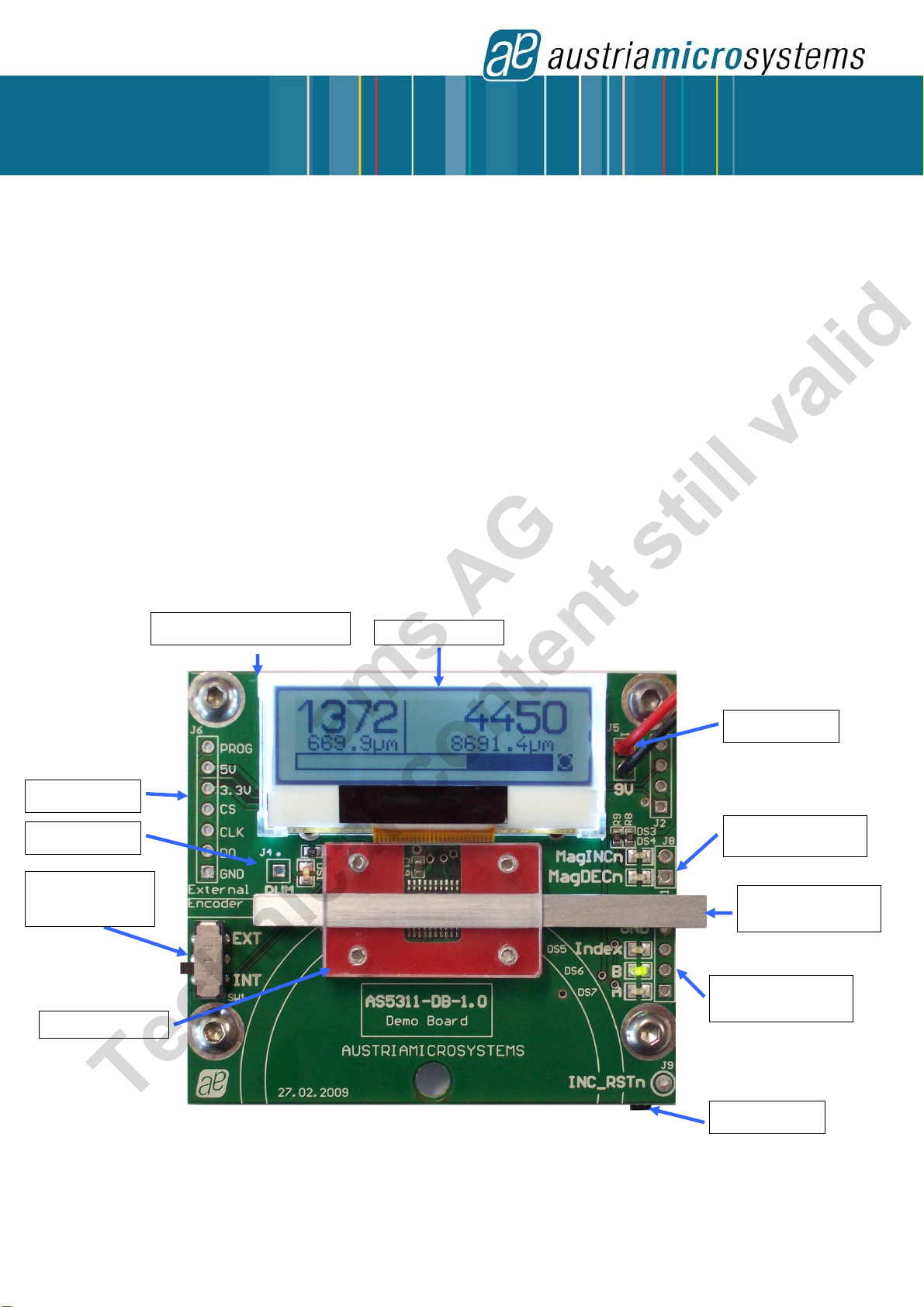
3.1.1 Graphic LCD display
The LCD display shows the realtime absolute and relative position of the magnet:
- The absolute position is read from the AS5311 serial output. The resolution is 0.488µm = 4096 positions per pole pair
(2mm). To use this feature with the onboard encoder, switch SW1 must be on position INT.
- The relative position is read from the incremental counter connected on the AB outputs of the AS5311. The resolution is
1.95µm / step. To use this feature with the onboard encoder, jumpers P1 and P2 (Bottom side) must be CLOSED.
Moving the slider from right to left will increase the absolute value until 4095 (1999µm) with 0.488µm steps, then returns to
0.
The incremental counter will increment on the same way with 1.95µm steps. To reset the relative position, press the push
button S1.
The magnet status indicator (magnet OK), U(magnet too close or too far, reduced accuracy), ±(magnet too close or
too far , values not valid and display stopped) is related to the magnet position.
Figure 2: LCD display in standalone mode (9V battery or USB powered without GUI)
3.1.2 PWM LED
bsolute position in a pole pair (2mm)
12 bit value (0 ~ 4095)
1 step = 0.488µm
Relative position from
quadrature AB counter in µm
Relative position from
quadrature AB counter
1 step = 1.95µm
bsolute position in a pole pair
0 ~ 1999µm
RELATIVE POSITION
1.95
m/ste
BSOLUTE POSITION
0.488
m/ste
Magnetic field status:
Magnet OK
UMagnet too far or too close,
reduced accuracy
±Magnet too far or too close,
value not valid
bsolute position bargraph
0~100% in a pole pair
This LED is connected to the PWM output of the AS5311. The PWM output is a pulse width that is proportional to the
position of a pole-pair of the magnet
The pulse width varies from 1μs to 4096μs typ with a repetition rate of 244 Hz typ.. When the position of the pole-pair is 0,
the LED is almost dark, as it is 1μs on and 4095μs off. Moving the magnet to the left increases the brightness of the PWM
LED, since the ON-pulse becomes longer and the OFF-pulse becomes shorter. The brightness of the PWM LED follows the
absolute position bargraph.
Likewise, the PWM output can be used as an analog output proportional to the angle, when the PWM signal is filtered by a
RC (or active) lowpass filter.
The PWM signal (0 ~ 3V3) can be directly taken from the connector J4.
3.1.3 Incremental quadrature AB-Index LED
The phase shift between channel A and B indicates the direction of the magnet movement. Channel A leads channel B
during a right-to-left movement of the magnet by 90 electrical degrees. Channel B leads channel A during a left-to-right
movement.
One Index pulse (3V3) is generated at each pole pair changes (see AS5311 datasheet Figure 9).
The AB-Index LEDs are directly connected to the A B Index outputs of the AS5311. These quadrature signals (0 ~ 3V3) are
available on connector J7.
Revision 1.0, 09 April 2009 Page 2 of 9
www.austriamicrosystems.com
ams AG
Technical content still valid